Page 4 Customer Care Center
1-800-898-1879
www.askousa.com
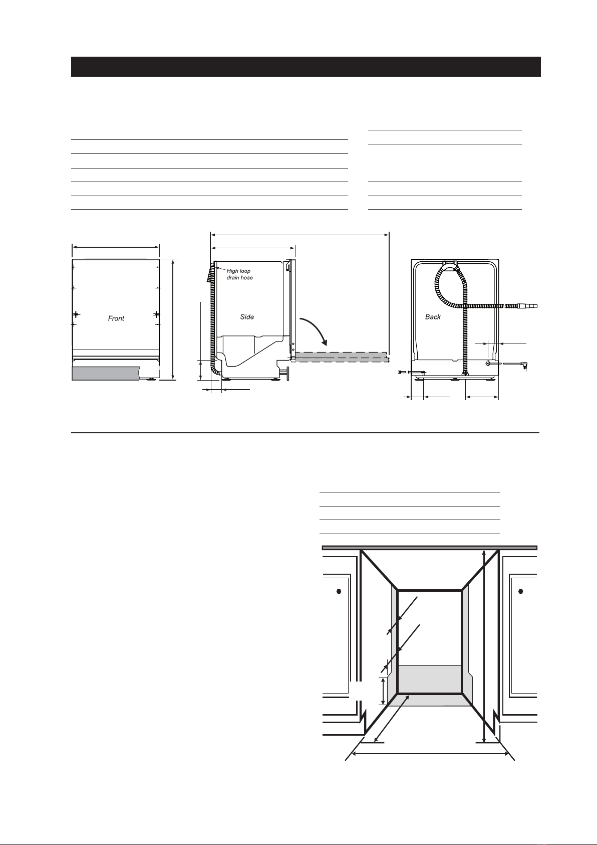
Height (Adjustable) 33-7/8˝ to 36˝ 860 mm to 914 mm
Width 23-5/8˝ 600 mm
Depth (Includes high loop) 22-7/8˝ 581 mm
Depth W/Door Open 49-1/2˝ 1257 mm
Weight 110 Ib 50 kg
Electricity 120V, 60Hz, 15 amp
Water pressure 4.2 - 140 psi,
0.03-1.0 MPa,
0.3-10 Bar
Heating element 1200 watt
Max loading 1300 watt
33-7/8" to 36"
860 mm to 914 mm
2-7/8"
73 mm
3-3/8"
86 mm
49-1/2"
1257 mm
5-3/8" to 7-3/8"
137 mm to 187 mm
23-5/8"
600 mm
22-7/8"
581 mm
9"
229 mm
3-1/8"
79 mm
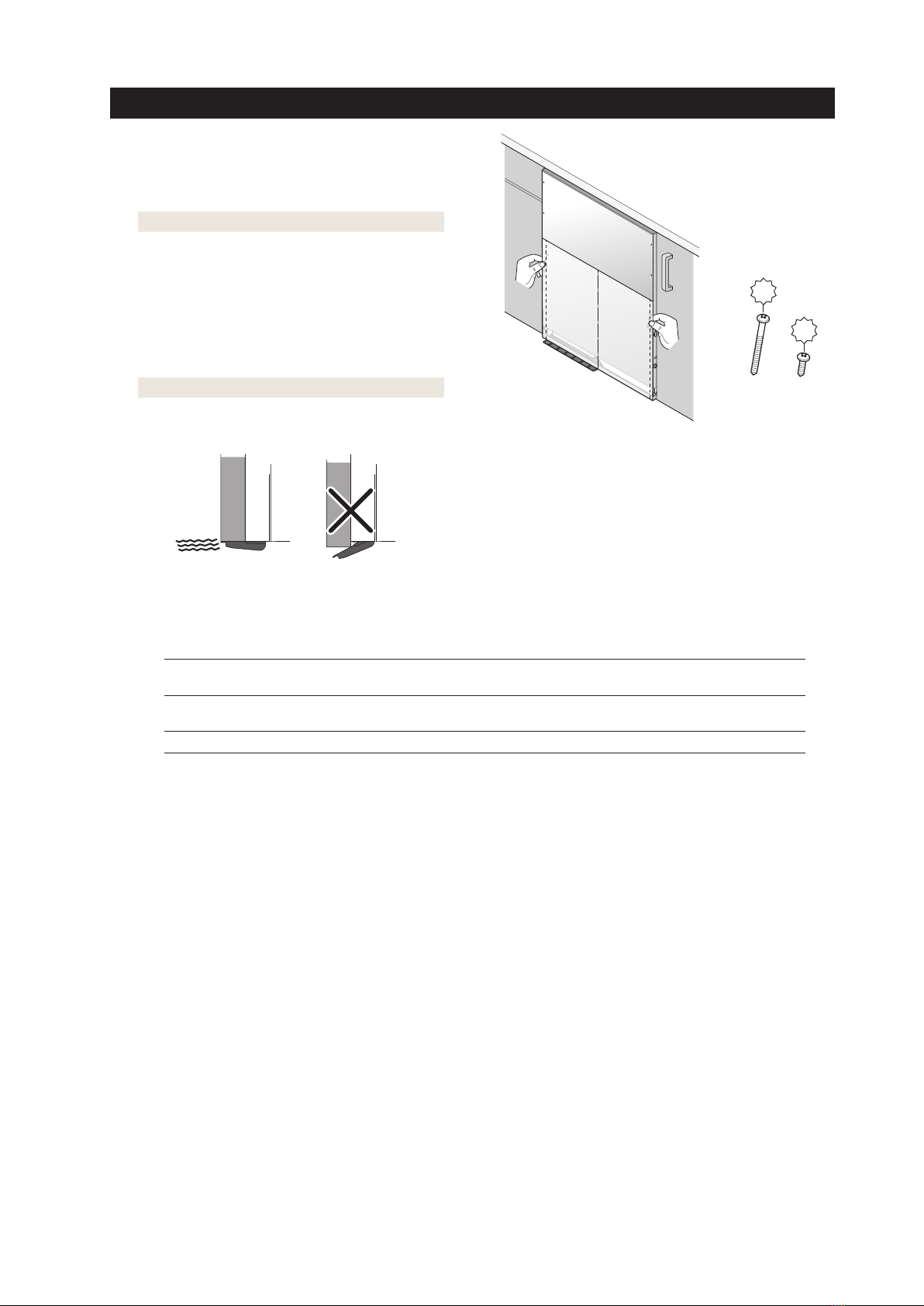
Door
The best place for your dishwasher is in the kitchen near
the sink. This makes it easier to connect the water and
drain supply lines.
A built-in dishwasher must be enclosed on the top, both
sides and the back.
The power-supply receptacle for the appliance shall
be installed in a cabinet or on a wall adjacent to the
undercounter space in whitch the appliance is to be
installed.
The electrical and water supplies should enter through the
area indicated by the shading on the illustration at right.
Preferably, they should come through the right side of the
machine. The access hole must be round and smooth and
no bigger than 1-1/2˝ (38 mm) in diameter. If the partition
is metal, it needs to be covered with an edge protector.
Use caution when the appliance is installed or removed, to
reduce the likelihood of damage to the power-supply cord.
Height** 33-7/8˝ – 36˝ 860 – 914 mm
Width 23-5/8 – 24˝ 600 – 610 mm
Depth 24˝ 610 mm
** If accessory FI ll strips are used, then 1/2˝ (13 mm) must
be added to the dishwasher height and cutout. Additionally,
3/8˝ (10 mm) must be added to the dishwasher width and
cutout width.
23-5/8" – 24"
600 – 610 mm
24"
610 mm
4"
102 mm
5-3/8"
136 mm
**33-7/8" – 36" minimum
**860 – 914 mm
2"
51 mm