Stevens CONTRACTOR MKIII Maintenance and service guide

CONTRACTOR MKIII
OWNER’S MANUAL
Safety, Operating and Maintenance Instructions
Please read and save these instructions.
For safety, read all safety and operating
instructions prior to operating the machine. Effective date Sept 2013

2
Manufacturer’s Warranty
The Manufacturer is Stevens Products Ltd, hereinafter referred to as the ‘Manufacturer’.
The user/owner is the original purchaser, hereinafter referred to as the ‘User’.
The Manufacturer’s obligation under this warranty is limited to correcting without charge at its
factory or by one of its authorised dealers, with the Manufacturer’s approval, any parts thereof,
within 12 (twelve) months from the date of purchase by the original User, and which upon
examination shall disclose to the Manufacturer’s satisfaction to have been originally defective.
Correction of such defect by repair to, or supplying of replacements of defective parts, shall
constitute fulfilment of all obligations to the original User. The Manufacturer shall not be liable for
loss, damage, or expense directly or indirectly from the use of its product or from any other cause.
Defective parts must be returned freight paid each way by the User to the Manufacturer.
Travel time to uplift or deliver the mower is specifically excluded from this warranty.
This warranty shall not apply to any parts which must be replaced because of normal wear, or
which have been subject to misuse, negligence or accident or which have been repaired or altered
outside of the Manufacturer’s factory, unless authorised by the Manufacturer.
This warranty should not be construed as a free service period during the warranty period.
No person, agent or dealer is authorised to give any warranties on behalf of the manufacturer or to
assume from the Manufacturer any other liability in connection with any of its products unless
made in writing from the Manufacturer.
The engine is covered by a separate Engine Manufacturer’s Warranty; see Engine Manual
enclosed for details or warranty period and servicing requirements.
Stevens Products Ltd
12 Andrew Baxter Drive
Airport Oaks
Auckland 2022
New Zealand
Ph: +649 275 0443

3
Owner Information: Date of Purchase:
Purchased From:
Serial Number:
The model of your machine is CON660III
Safety Guide
Protect yourself and others by following these safety steps:
a) Know your controls. Learn how to stop the engine quickly in an emergency.
b) NEVER MOW WITH THE DISCHARGE FLAP OPEN OR BELT GUARD OFF.
c) Make sure the lawn is clear of sticks, stones, wire and debris. They could be thrown by the
blade and cause serious injury.
d) Add fuel BEFORE starting the engine. Avoid spilling petrol and do not fill the tank while the
engine is running or while you are smoking.
e) Avoid mowing while people, especially children, or pets are nearby.
f) Disengage blade and drive clutches before starting.
g) Start the engine carefully with feet well away from the blades.
h) Do not operate the engine in a confined space where carbon monoxide fumes can collect.
i) Stop the engine whenever you leave the mower, even for a moment.
j) Check all nuts, bolts, and screws often. Always be sure that the mower is in a safe
operating condition.
k) Stop the blade before driving the mower across gravel drives, walks or roads.
l) Do not allow children or people unfamiliar with the mower to operate it.
m) On slopes or wet grass, be extra careful of your footing.
n) Avoid cutting grass by pulling the mower towards you; you could pull the mower back on
top of yourself.
o) Stop the engine and disconnect the spark plug wire before checking or working on the
mower.

4
Operating your Mower
Starting the Engine
Fill the fuel tank with clean unleaded fuel and check the oil level on the dipstick before attempting
to start the engine. Open the fuel tap under the fuel tank by pushing it backward as shown on the
pictorial diagram on the top of the air cleaner cover.
Ensure the blade drive is disengaged and then open the throttle to full choke if the engine is cold.
If starting a warm engine full choke will not be necessary. Pull briskly on the starter rope and once
the engine starts throttle back to mid- revs than back to idle and allow the engine to warm up for a
few minutes.
Engaging and disengaging the Blade
To engage the blade drive belt, shift the lever at the centre rear of the mower (just below the
engine) to the right and down into the locked on position with your foot.
Use low to mid engine revs to engage and disengage. Never engage/disengage at full revs; belt
damage will occur and belt life will be shortened considerably.
Easing the drive in gently will help belt life and provide a smooth take-up for the blade drive.
To disengage, bring the engine revs back to low, then flick the lever up with your foot and push it
gently to the left to bring the blade to a complete stop.
Operator Presence Park Brake
The unit is equipped with an Operator Presence Park Brake which uses a locking pawl on both the
rear wheels. Note! It is not intended as a service brake to slow the unit down.
This brake is operated by the lever on top of the right-hand handle.
To release the brake and achieve neutral, press the operator presence handle all the way down
with the palm of your hand as you take hold of the handle bars.
Self-Propelled Forward Drive
The unit is independent rear wheel drive meaning the rear wheels can be powered independently
to aid steering and hillside traction.
To engage the drive, squeeze the levers up under the handles. To make a turn, release the side
you wish to turn towards, and the other wheel will steer the unit round.
To back up or simply push the mower without self-propel, just actuate the operator presence lever
only and the unit will free-wheel both directions.
Cutting Height Adjustment
The MKIII Contractor uses a single lever height adjustment for all four wheels. The most forward
position is the highest cutting position, the most rearward position is the lowest position. The
height of cut ranges from 1” to 4” in ½” increments. The adjusting lever is located at the left hand
rear of the machine, beside the fuel tank.
To adjust the height, pull the lever away from the body of the machine to disengage the locking pin
then while holding it out slide the lever forward or rear to the desired height and lock the handle
back into one of the available hole positions.

5
Adjustments
Blade Drive Belt Tension
The blade drive belt tension is adjustable by shifting the idler pulleys into different holes on the
arm. Setting the belt with the minimum tension required to drive will increase service life.
Remove the top spindle guard to access the two idler pulleys. The factory setting for the pulleys is
the forward one nearest the inside of the machine and the rear one nearest the outside of the
machine.
As the belt wears and stretches, it can be compensated by shifting the rear idler pulley nearer the
centre. One hole of adjustment will normally be sufficient. Any more than this will result in the belt
not disengaging when the brake is applied and will burn out the belt prematurely.
Wheel Drive Belt Tension
The cables from the operating levers to the drive levers are adjustable at both ends. Stevens
recommend adjusting the top end at the handle. You should not need to adjust the bottom end
ever. If the drive belts are slipping frequently or the levers are pulling right up to the hand grips,
Adjust the nuts to tighten the cable. Check the unit does not drive when in neutral (see ‘Operator
Presence Lever – Neutral Position’).
If replacing the cables, fit the bottom end first with the nuts backed off as far as they can go then
adjust the top end to achieve correct tension.
Gearbox Belt Tension
The gearbox belt is tensioned by a spring idler so no adjustment is necessary.
Periodically check the belt for wear; access is by removing the four bolts holding the rear closure
plate on. Check the idler bearings for free motion at the same time.
Operator Presence Lever - Neutral Adjustment
The operator presence lever can be adjusted by loosening the locknut on the countersunk bolt and
screwing the bolt further in or out as necessary. Winding the bolt further in will tighten the drive
belts and lift the levers higher; winding the bolt further out will slacken the belts and drop the
handles.
The ideal setting is as tight as can be achieved before the belts begin to drive the mower forward
with only the operator presence lever pressed down.
Tyre Pressures
The front tyres are solid rubber and not inflatable.
The rear tyres are pneumatic and should be inflated to 20 PSI. Do not inflate to the maximum
shown on the sidewall of the tyre; this will not be the ideal pressure for this application.
Throttle Cable
Periodically the throttle cable will need adjusting. With the lever pushed all the way to the left the
bottom end of the cable should just activate the rubber cover stop plunger. It will make a small
‘click’ if operating correctly. Full throttle will open the choke for starting. Hard starting may
indicate the choke is not being fully opened. To adjust the throttle, loosen the clamp over the
outer cable sheath at the engine and slide up or down as necessary to get the correct position.
Sliding it up will increase the choke and sliding it down will do vice versa.

6
Maintenance
Greasing
Grease front wheels and spindle top nipple every 25hrs. The spindle is fitted with a grease relief
valve (under the deck) so supply sufficient grease until the excess pushes out the valve.
Belts
Adjust belt tension as described under ‘Adjustments’ and replace belts when excessive wear or
damage begins to show. As belt lengths vary from different manufacturers, ensure replacement
belts are performing correctly when fitted.
Engine Oil
Check the engine oil level daily; see separate engine owner’s manual for details.
Replace engine oil at the intervals specified in the Engine Owner’s Manual.
The oil specification the units are filled with at the factory is Mineral Oil 10W30.
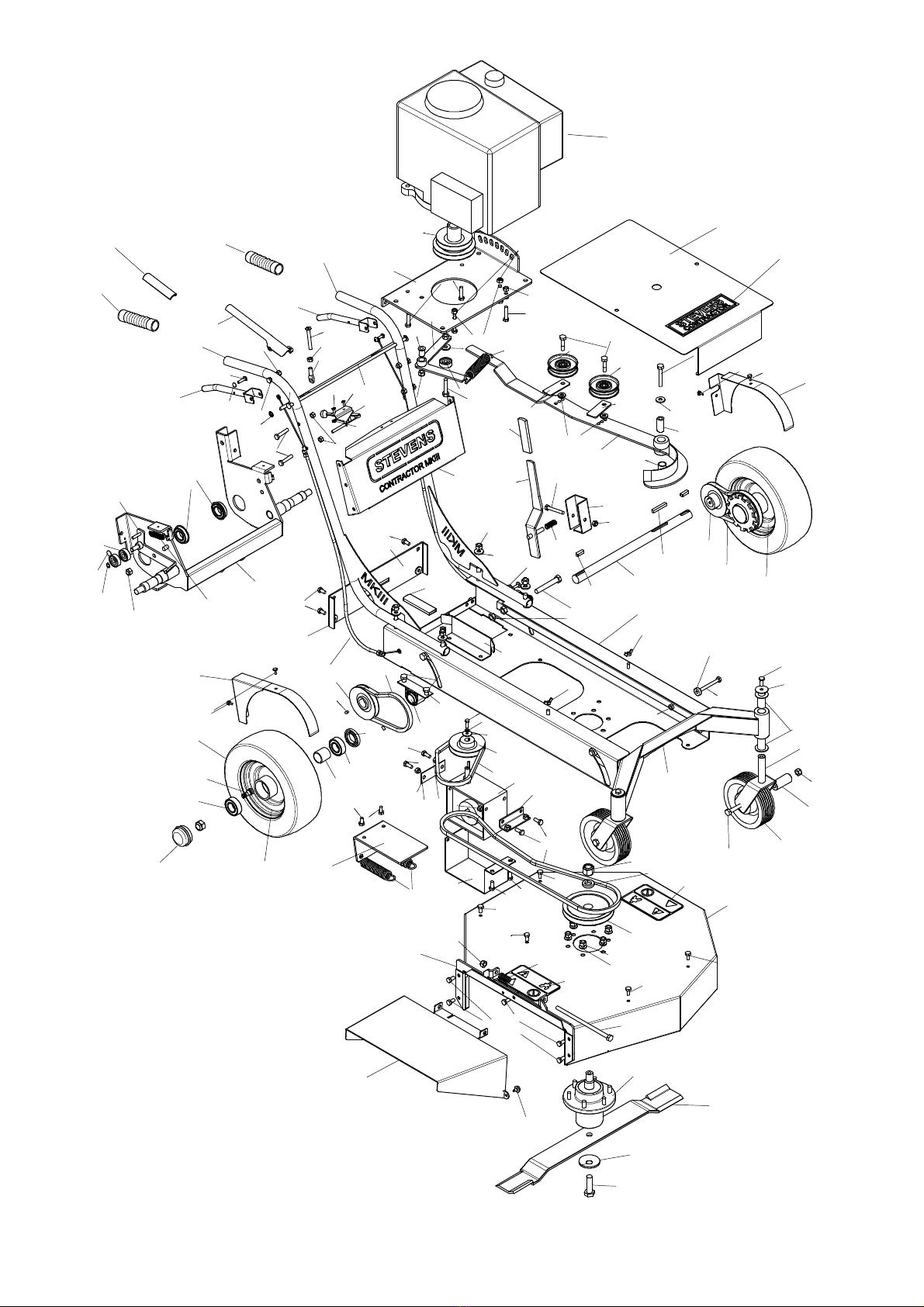
Spare Parts
Availability
All spare parts are available from the manufacturer should you be unable to obtain them through
your local dealer. It is the manufacturer’s objective to assist to ensure any downtime is kept to a
minimum.
Part Numbers
Ordering by part numbers will help, but we will always endeavour to have trained sales persons
familiar with your machine available to assist with parts identification.
The diagram and list at the rear of this book is current at time of printing however specifications
are subject to change without notice.
Options
Mulching Kit
Stevens make a mulch kit which is available for any 660MKIII. This blocks the discharge to
provide recycling of the clippings for a well maintained lawn mowed regularly.
This kit consists of a baffle and mulch blade. The baffle can be fitted with no tools required. The
blade requires the use of a 24mm socket to remove the blade bolt and refit. If desired, the mulch
blade can be left on for side discharge as well, but it does use more horsepower.
Mud Grip Rear Tyres
Optional mud-grip rear tyres can be fitted at the factory for no extra charge or purchased as an
option later.
They provide better grip in wet or slippery situations where the regular turf pattern may clog and
lose traction.
1200
1201
1202
1203
1204
1206
1207
1208
1209
1210
1211
1212
1213
1214
1217
1218
1219
1224
1226
1228
1251
022
030
031
038
041-6
044
044
084
110
1028
1220
1221
1222
1223
1227
1229
1230
1231
1232
1233
1240
1241
1242
1242
1250
1253
1254
1255
1256
1257
70240
793778
14076-00
14076-00
14076-00
6005NR-2RS
608-2RS
6205-2N
6300-LLU
7705-1
8600-28
8600-28
A21
A21
A55
AS205
1225
SF027
SF117
SF118
SF039
SF039
SF039
SF039
SF039
SF006
SF006
SF005
SF005
SF005
SF016
SF099
SF093
SF100
SF016
SF101
SF103
SF007
SF007
SF004 SF007
SF004
SF007
SF027
SF104
SF006
SF105
SF041
SF120
SF012
SF044
SF002
SF109
SF062
SF058
SF002
SF016
SF108
SF058
SF028
SF024
SF106
SF002
SF110
5245
1233
SF024
5245
SF111
SF119
SF113
SF082
PP205
1258
SF114
782474
SF115
SF116
1261
1260
SF004
6205-2N
094
SF006
1216
1262
SF058
SF112
SF082
SF082
F002
F028
1263
SF058
029-1
SF107
SF058
1215
A21
1251
970-1
SF102
1205
6300-LLU
SF039
1028

PartNo.DescriptionQty
022FrontWheelBush2
029‐1StevensContractorDecal1
030EngineThrottleCable1
031GreaseCap2
038HondaGXV340engine1
041‐6Gearbox‐25:1ReductionRatio1
044RoundHandleGrip2
084RearWheelSeal2
094RearWheelBearingSpacer2
095SerialPlate1
110FrontWheel2
1028HeightAdjusterSpring/IdlerSpring3
1200660MKIIIChassis1
1201660MKIIIMowerBowl1
1202FrontWheelSub‐Frame1
1203RearWheelSub‐Frame1
1204EngineMountPlate1
1205GearboxBeltIdlerArm1
1206L.HHandle1
1207R.HHandle1
1208HeightAdjusterHandle1
1209L.HClutchLever1
1210R.HClutchLever1
1211L.HWheelDriveBeltTensioner1
1212R.HWheelDriveBeltTensioner1
1213GearboxAngleMountBracket1
1214OperatorPresenceActuator1
1215L.HWheelHub‐W/Pulley1
1216R.HWheelHub‐W/Pulley1
1217CastorFork2
1218DischargeOpeningStiffener1
1219RearClosurePlate1
1220DeckBeltGuide1
1221SpringAnchorPlate1
1222GearboxGuard1
1223Spindle1
1224BladeBeltTensioner1
1225SteelPivotBush1
1226EngineDrivePulley1
1227OperatorPresenceGrip1
1228GearboxInputPulley1
1229HandleFrameCrossStiffener1
1230ChuteReturnSpring1

PartNo.DescriptionQty
1231WheelDriveBeltTensionerSpring2
1232HeightAdjusterOuterGuide1
1233DeckBeltIdlerGuides2
1240DischargeChuteRubberBumper1
1241WheelDriveClutchCables2
1242CastorFork/DeckBeltBushes6
1250MainDriveShaft1
1251WheelDrivePulley2
1252DecalThrottle1
1253FabricatedChute1
1254DriveGuardL.H1
1255DriveGuardR.H1
1256TyreValve2
1257TopSpindleCover1
1258Gearboxpacker(variablethicknesstosuit)1
12607x8x50Key1
12617x8x25Key2
126210mmExternalCirclip2
1263NylonBush10x16x201
1264EngineShaftKey1/4"x40mmlong1
14076‐00FlatHandleGrip3
5245BladeIdlerPulley2
6005NR‐2RSRearHeightAdjusterBearing2
608‐2RSFrontHeightAdjusterBearing2
6205‐2NRearWheelBearing4
6300‐LLUBeltIdlerBearing6
70240RearTyre‐TurfPattern2
75440RearTyre‐MudGripPatternOPTIONAL2
7705‐1Blade1
7824745/8”DomedFlatWasher1
793778BladeSpindlePulley1
8600‐28Decal‐Warning2
970‐1HeightAdjusterHandleSpring1
A21WheelDriveBelt/GearboxDriveBelt3
A55DeckBelt1
AS205PillowBlockBearing1
PP205PillowBlockHousing1
F002F002StarLockNut2
F028F026PhilipsHeadScrew2
SF002M10HeavyFlatWasher6
SF003M8LightFlatWasher4
SF004M8NylocNut6
SF005M8x25mmHexHeadBolt6

PartNo.DescriptionQty
SF006M8x20mmHexHeadBolt6
SF007M8PlainNut8
SF012M6SpringWasher1
SF016M8x40mmHexHeadBolt6
SF0243/8"FlatWasher12
SF027M8WingNut2
SF0283/8”UNCNylocNut6
SF039M8x16mmHexHeadBolt10
SF041M10x20mmHexHeadBolt2
SF058M10NylocNut10
SF062M12Nut2
SF071M10x40mmHexHeadBolt1
SF082M6x20mmHexHeadBolt4
SF093M8x70mmHexHeadBolt2
SF099M8x60mmHexHeadBolt1
SF100M8x70mmCountersinkSocketHeadBolt1
SF1015/16"UNFx11/4"HexHeadBolt2
SF1025/16"UNFx11/2"HexHeadBolt2
SF1035/16"UNFNylocNut2
SF104M8FemaleTurnbuckleEnd1
SF105M8PanelWasher–35mmOD2
SF106M10x60mmHexHeadBolt1
SF107M10x80mmHexHeadBolt2
SF108M10x200mmHexHeadBolt1
SF109M12x80mmHexHeadBolt2
SF1103/8”UNCx1½”HexHeadBolt2
SF111M5StarDomeLockWasher2
SF112M6StarDomeLockWasher2
SF113M8StarDomeLockWasher2
SF1145/8”UNCx2”HexHeadBolt1
SF115¾”UNFNylocNut1
SF116¾”SpringWasher1
SF117M6x25mmSocketButtonHeadScrew2
SF118M6x10mmGrubscrew4
SF119M8PlainStarWasher1
SF120M6PanelWasher(1/4"x1"x16G)1
SF1217/16"UNFxHexHeadBolt1
SF1227/16"SpringWasher1


