Toro 70082 User manual

1163

E
Than you for purchasing a Toro product.
All of us at Toro want you to be completely satisfied
with your new product, so feel free to contact your
local Authorized Service Dealer for help with service,
genuine replacement parts, or other information you
may require.
Whenever you contact your Authorized Service DealĆ
er or the factory, always now the model and serial
numbers of your product. These numbers will help
the Service Dealer or Service Representative provide
exact information about your specific product. You
will find the model and serial number plate located in
a unique place on the product as shown below.
1
2363
1. Model and Serial Number Plate (on left frame)
For your convenience, write the product model and
serial numbers in the space below.
Model No:
Serial No.
Read this manual carefully to learn how to operate
and maintain your product correctly. Reading this
manual will help you and others avoid personal injuĆ
ry and damage to the product. Although we design,
produce and mar et safe, stateĆofĆtheĆart products,
you are responsible for using the product properly
and safely. You are also responsible for training perĆ
sons, who you allow to use the product, about safe
operation.
The warning system in this manual identifies potenĆ
tial hazards and has special safety messages that
help you and others avoid personal injury, even
death. DANGER, WARNING and CAUTION are signal
words used to identify the level of hazard. However,
regardless of the hazard, be extremely careful.
signals an extreme hazard that will cause
serious injury or death if the recommended precauĆ
tions are not followed.
signals a hazard that may cause serious
injury or death if the recommended precautions are
not followed.
signals a hazard that may cause minor or
moderate injury if the recommended precautions are
not followed.
Two other words are also used to highlight informaĆ
tion. Important" calls attention to special mechanical
information and Note" emphasizes general informaĆ
tion worthy of special attention.
The left and right side of the machine is determined
by sitting on the seat in the normal operator's posiĆ
tion.
The engine exhaust from this product
contains chemicals known to the State of
California to cause cancer, birth defects,
or other reproductive harm.

2
TABLE OF CONTENTS
P ge P ge
Introduction 1. . . . . . . . . . . . . . . . . . . . . . . . . . . . . . . . . .
S fety 3. . . . . . . . . . . . . . . . . . . . . . . . . . . . . . . . . . . . . .
Slope Ch rt 6. . . . . . . . . . . . . . . . . . . . . . . . . . . . . . . . . .
S fety Dec ls nd Instructions 7. . . . . . . . . . . . . . . . . .
Specific tions 8. . . . . . . . . . . . . . . . . . . . . . . . . . . . . . . .
Loose P rts 9. . . . . . . . . . . . . . . . . . . . . . . . . . . . . . . . .
SetĆUp Instructions 10. . . . . . . . . . . . . . . . . . . . . . . . . .
Inst ll Front Wheels 10. . . . . . . . . . . . . . . . . . .
Inst ll Steering Wheel 10. . . . . . . . . . . . . . . . .
Inst ll Se t 10. . . . . . . . . . . . . . . . . . . . . . . . . . .
Activ ting nd Ch rging B ttery 11. . . . . . . .
Fill Cr nkc se With Oil 11. . . . . . . . . . . . . . . . .
Fill Fuel T nk With G soline 12. . . . . . . . . . . .
Check Tire Pressure 12. . . . . . . . . . . . . . . . . . .
Controls 13. . . . . . . . . . . . . . . . . . . . . . . . . . . . . . . . . . . .
Oper tion 14. . . . . . . . . . . . . . . . . . . . . . . . . . . . . . . . . . .
St rting 14. . . . . . . . . . . . . . . . . . . . . . . . . . . . . .
Stopping 14. . . . . . . . . . . . . . . . . . . . . . . . . . . . .
Bre kĆIn 14. . . . . . . . . . . . . . . . . . . . . . . . . . . . .
Using P rking Br ke 14. . . . . . . . . . . . . . . . . . .
Adjusting HeightĆofĆCut 14. . . . . . . . . . . . . . . .
Oper ting Procedure 14. . . . . . . . . . . . . . . . . .
Side Disch rging or B gging 15. . . . . . . . . . .
Gr ss Deflector 15. . . . . . . . . . . . . . . . . . . . . . .
Recycler Rider Tips 15. . . . . . . . . . . . . . . . . . . . . . . . . .
M inten nce Interv l Ch rt 17. . . . . . . . . . . . . . . . . . . .
M inten nce 18. . . . . . . . . . . . . . . . . . . . . . . . . . . . . . . . .
Gre se Front Axle Spindles nd Wheels 18.
Lubric te Pivot Points 18. . . . . . . . . . . . . . . . . .
Check/Ch nge Cr nkc se Oil 19. . . . . . . . . .
Servicing Air Cle ner 19. . . . . . . . . . . . . . . . . .
Repl cing Sp rk Plug 20. . . . . . . . . . . . . . . . .
Dr ining G soline From Fuel T nk 20. . . . . . .
Servicing Cutter Bl de 21. . . . . . . . . . . . . . . . .
Removing/lnst lling Cutting Unit 22. . . . . . . .
Repl cing Bl de Drive Belt 22. . . . . . . . . . . . .
Adjusting Bl de Drive Belt 22. . . . . . . . . . . . . .
Repl cing Tr ction Drive Belt 23. . . . . . . . . . .
Adjusting Front Wheel Alignment 24. . . . . . . .
Adjusting Br ke 24. . . . . . . . . . . . . . . . . . . . . . .
Leveling Cutting Unit 24. . . . . . . . . . . . . . . . . .
Adjusting Ge r Shift Neutr l Position 25. . . .
Checking Interlock System 25. . . . . . . . . . . . .
W shing Underside of Mower 26. . . . . . . . . .
Stor ge 27. . . . . . . . . . . . . . . . . . . . . . . . . . . . . .
Wiring Di gr m 28. . . . . . . . . . . . . . . . . . . . . . . . . . . . . .
Troubleshooting 29. . . . . . . . . . . . . . . . . . . . . . . . . . . . . .
W rr nty B ck Cover. . . . . . . . . . . . . . . . . . . . . . . . . . . .
The enclosed Engine Owner's Manual is su lied for California
Emission Control Regulation information on emission systems,
maintenance and warranty.
Kee this engine Owner's Manual with your unit. Should this enĆ
gine Owner's Manual become damaged or illegible, re lace imĆ
mediately. Re lacements may be ordered through the engine
manufacturer.

This machine is capable of amputating hands
and feet and can throw objects that can cause injury
and damage. KNOW the controls and how to stop
machine quickly. READ THIS OPERATOR'S MANUAL
and instructions furnished with attachments. Read,
understand, and obey all safety messages appearĆ
ing on the machine and in the operator's manual.
LEARN from your operator's manual and from careĆ
ful E PERIENCE how to operate your equipment
correctly. Know your machine's limitations.
Keep hands, feet, hair and loose clothing away
from attachment discharge area, underside of mowĆ
er deck or any moving parts while engine is running.
The use of drugs or alcohol while operating any
equipment will place your safety in peril. Do not atĆ
tempt operation of this machine while taking drugs
or medication or while drinking alcoholic beverages.
Only responsible persons with mature judgment
and proper physical capabilities should be allowed
to operate this machine, and only after instruction in
the proper use of this equipment.
Do not allow children to operate machine.
Do not carry passengers.
The purpose of this machine is to perform work.
This equipment is not intended for sport or recreĆ
ation.
Do not mow when people or pets are around.
Clear work area of objects (wire, rocks, etc.)
which might be picked up and thrown.
Take all possible precautions when leaving veĆ
hicle unattended; disengage powerĆtakeĆoff, lower
attachments, shift into neutral, set parking brake,
stop engine and remove key.
Watch out for traffic when crossing or near roadĆ
ways.
Machine and attachments should be stopped
and inspected for damage after striking a foreign
object. Damage should be repaired before restarting
and operating equipment.
Do not change engine governor settings or
over-speed engine.
Wear appropriate protective clothing when operĆ
ating equipment. Long pants and substantial footĆ
wear are essential. Do not operate with bare feet or
open sandals.
Do not operate equipment unless properly
seated with feet on footrests or pedals.
Keep your eyes and mind on your machine, atĆ
tachment and the working area. Do not let other inĆ
terests distract you.
Safety switches are intended to stop or prevent
starting of engine to help prevent accidents.
OPERATOR SHOULD TAKE PRECAUTIONS AND
NOT RELY ENTIRELY ON SAFETY SWITCH(ES).
Check switches for proper operation before each
use.
Care should be used not to touch equipment or
attachment parts which may be hot from operation.
Muffler and nearby areas may exceed 150_ F. Allow
cooling to occur before attempting to maintain, adĆ
just or service.
Use of stereo headphones, ear protection or othĆ
er sound altering/dampening devices may limit your
ability to hear warning sounds (horns, shouts, etc.).
Handle gasoline with care. It is highly flammable.
Use approved gasoline container. Place containĆ
er out of reach of children.
Use gasoline only as a fuel Ċ never as a cleaner.
Never remove fuel cap or add gasoline to a runĆ
ning or hot engine, or an engine that has not been
allowed to cool for several minutes after running.
Never fill fuel tank indoors. Wipe up spilled gasoĆ
line.
Open doors if engine is run in garage Ċ exhaust
fumes are dangerous. Do not run engine indoors.
Do not fill machine with gasoline while smoking
or when near open flame or sparks.
Never store equipment with gasoline in the tank
inside a building where fumes may reach an open
flame or spark.
Allow engine to cool before storing in any encloĆ
sure.
To reduce fire hazard, keep engine and attachĆ
ments free of grass, leaves or excessive grease.
Battery acid is a poison and can cause burn.
Avoid contact with skin, eyes and clothes and proĆ
tect your face, eyes and clothing when working
around the battery.
Battery gases can explode. Keep cigarette,
sparks and flames away from battery.

It is recommended that first operation of equipĆ
ment be done at a slow speed with attachment disĆ
engaged. Continue this practice until operator is
thoroughly familiar with the controls and has develĆ
oped operating skills.
Disengage all attachment clutches, set parking
brake and shift into neutral before attempting to start
engine.
Disengage power to attachment(s), set parking
brake and stop engine before leaving operator posiĆ
tion.
Disengage power to attachment(s) and stop enĆ
gine before making any repairs or adjustments.
Disengage power to attachment(s) when transĆ
porting or not in use.
Disengage attachment clutch before attempting
to remove the mower from a hole or other obstrucĆ
tion.
Disengage power to attachment(s) before backĆ
ing. Do not mow in reverse unless absolutely necesĆ
sary and then only after careful observation of the
entire area behind the machine.
LOOK behind machine to make sure the area is
clear before placing the machine in reverse and conĆ
tinue looking behind while backing.
Always back up loading ramps and tilt bed trailĆ
ers.
The parking brake is designed to hold machine
in place at rest, with engine off. Parking brake will
not restrain machine with engine running and transĆ
axle engaged.
Know the terrain on which you are operating
your equipment. There are areas on which your
equipment cannot be safely operated.
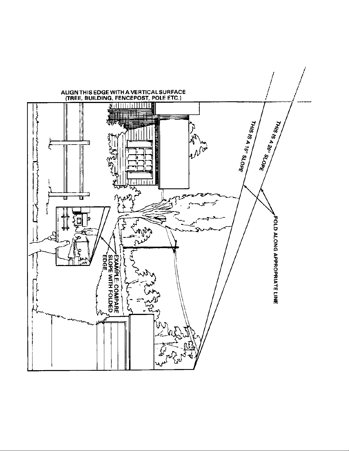
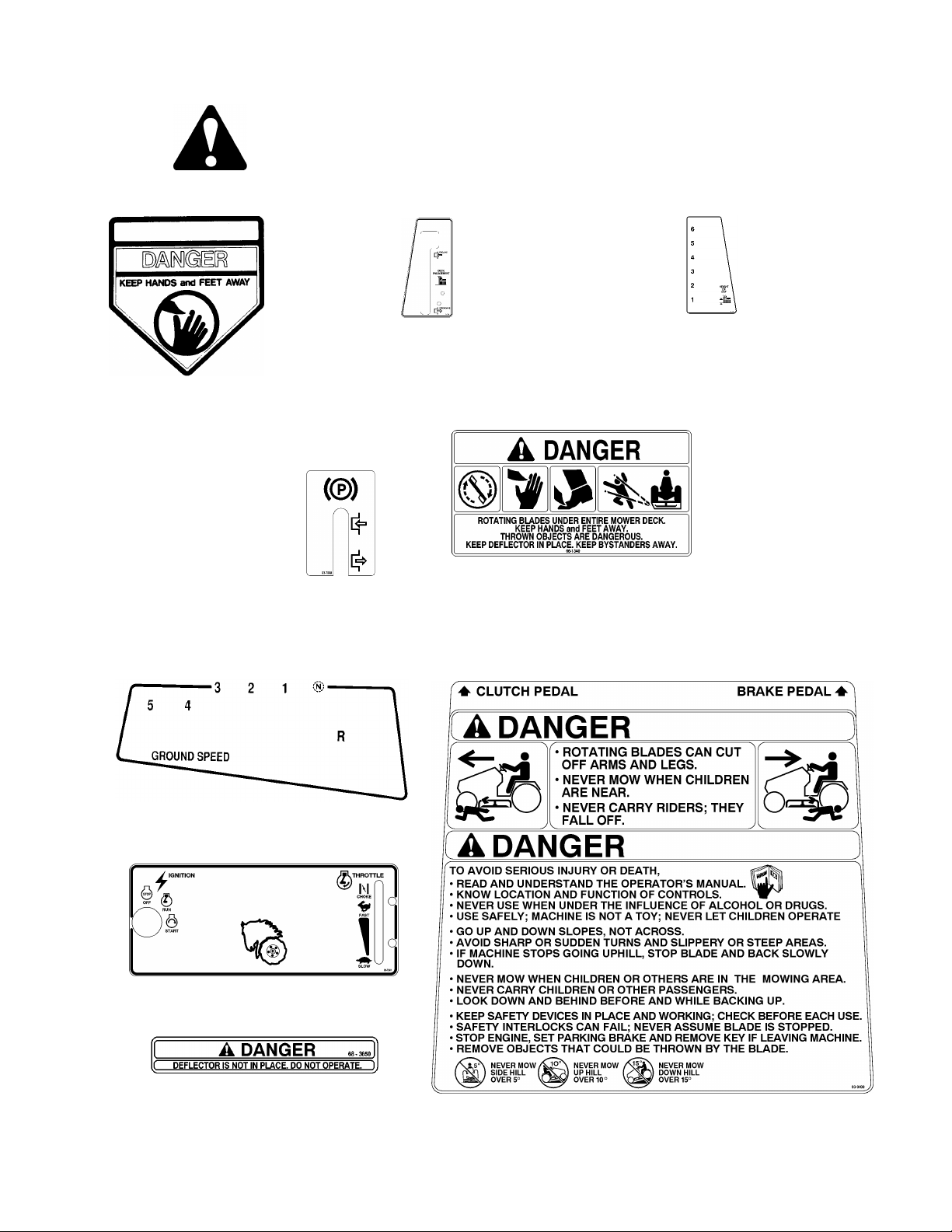
Avoid operating equipment on hillsides, slopes
or rough terrain. DO NOT operate machine on hillĆ
sides or slopes exceeding 15_ (27% grade). If safety
is in doubt TAY OFF THE LOPE.
Reduce speed and exercise extreme caution on
slopes above 10_ (18% grade) to prevent tipping or
loss of control. Never mow uphill on these slopes Ċ
mow downhill only. If a steep hill must be ascended,
back up the hill, and drive forward down the hill,
keeping machine in gear. If necessary to turn on hill,
always turn downhill.
Mow up and down the face of slopes greater
than 5_ (9% grade), never across the face. Be espeĆ
cially cautious when changing directions on all
slopes.
Operate your machine smoothly and at a ground
speed slow enough to ensure complete control at all
times. Avoid erratic operation and excessive speed.
harp turns on any terrain may cause loss of
control. Reduce speed and use caution when makĆ
ing sharp turns.
Do not stop or start suddenly when going uphill
or downhill. Avoid uphill starts. If machine is stopped
going up a slope, turn the attachment off and back
slowly down the slope keeping the machine in gear.
Do not stop or change gears (speed) on slopes.
Know the terrain on which you are working. Find
hidden obstacles by walking through and inspecting
the area prior to operating your equipment in that
area. Plainly mark obstacles, such as rocks, ruts or
holes and stay well clear of these obstacles when
operating.
While operating, stay alert for holes, rocks or
roots, which may cause damage to equipment or
upset. Keep at least 3 ft. away from dropĆoffs,
ditches, creeks, culverts, washouts and public highĆ
ways.
Exercise care when mowing around a fixed obĆ
ject to prevent the equipment or attachment from
striking the object. When mowing, never deliberately
run over any foreign object.
Areas wet with dew, rain or snow will be more
slippery than when dry. Areas covered with loose
gravel are more slippery than firm, dry ground.
Greater stopping distances are required in these
slippery areas.
Learn to expect changes in operating conditions.
Adding or removing attachments or weight to your
equipment will make your machine perform differentĆ
ly. Rain, snow, loose gravel, wet grass, etc., change
the tractive conditions of the terrain, requiring
changes in your operating technique, which may
include a decision not to operate on that terrain.
Use care when pulling loads or using heavy
equipment.
A. Use only approved drawbar hitch points.
B. Limit loads to those you can safely control.
C. Do not turn sharply. Use care when backing.
D. Use counterweight(s) or wheel weights when
suggested in operator's manual.

W en using attac ments never direct disc arge
of material toward bystanders nor allow anyone near
ve icle w ile in operation.
W en using mac ine wit mower:
A. Mow only in daylig t or in good artificial lig t.
B. Never make a cutting eig t adjustment w ile
engine is running if operator must dismount
to do so.
C. S ut engine off and wait for all moving parts
to stop before unclogging c ute.
D. C eck blade mounting bolts for proper tig tĆ
ness at frequent intervals.
Keep ands and feet away from rotating blade(s)
underneat mower deck. Never place foot on
ground w en mower is engaged or w en unit is in
motion.
DO NOT operate mower attac ment wit out t e
c ute deflector or complete bagger in place.
Exercise care w ile maneuvering wit grass
catc er. Front to rear stability may c ange.
Keep all nuts, bolts, fasteners and screws tig t
to be sure equipment is in safe working condition
and c eck t em frequently. Repair or replace worn,
damaged, distorted or broken parts as needed.
Keep ve icle and attac ments in good operating
condition and keep safety devices in place and
working.
Under normal usage, grass catc er bag material
is subject to deterioration and wear. It s ould be
c ecked frequently to determine need for bag reĆ
placement.
Use only genuine Toro W eel Horse replacement
parts to ensure t at original standards are mainĆ
tained.
S ields, deflectors, switc es, decals, blade conĆ
trols and ot er safety devices must be in t eir proper
position and functional.
Do not operate wit out muffler or tamper wit
t e ex aust system. Damaged mufflers or spark arĆ
resters can create a fire azard. Periodically inspect
and replace if necessary.
If equipment begins to vibrate abnormally, disenĆ
gage power to attac ments and stop engine at
once. Repair any damage before starting or continuĆ
ing operation.
Periodically inspect all s afts, levers, friction deĆ
vices and ot er moving parts subject to wear. Make
required adjustment or replace t ese parts if damĆ
aged, distorted or broken, or as soon as wear affects
t e normal operation of t e ve icle or attac ment.
DO NOT operate equipment t at is not functioning
properly.

6
10_ SLOPE CHART
Read all safety instr ctions on pages 3-7

"
#%& $ '
#%& $
!
#%& $
#%& $
#%& $
#%& $
#%& $
#%& $
#%& $

8
SPECIFICATIONS
1232 REAR ENGINE RIDER - ELECTRIC START
11Ć32 Ċ Briggs & Stratton Engine: I/C Series, elecĆ
tric start with alternator, four cycle engine. Crankcase
oil capacity is 48 ounces (1.42 l) and fuel tank caĆ
pacity is 5 quarts (4.73 l). Correct spark plug is a
Champion RJĆ19 M or equivalent resistor type. RecĆ
ommended spark plug air gap is 0.030 of an inch
(0.762 mm).
Mower Housing: Full floating, front to rear, side to
side. 13 gauge (2.64 mm) stamped steel housing
with kickers, discharge cover, ring and side disĆ
charge grass deflector. Deck diameter is 31.75 inĆ
ches (.8 m). Cast spindle housing with shaft is supĆ
ported by two double seal ball bearings. Blade
spindle pulley is driven by A" section VĆbelt from enĆ
gine crankshaft.
Cutter Bla e: Single blade is 31.35 inches (0.796 m)
long, made of one piece hardened 7 gauge (2.72
mm) carbon steel.
Bla e Tip Spee : 17,000 ft./min. (86.36 m/s) @
3300 engine rpm. Height-of-Cut Range: adjustable
to one of six approximate settings from 1Ć1/2 inches
to 4 inches (38 to 101 mm).
Transaxle: Transaxle fully enclosed, permanently
lubricated with five speeds forward and one reverse.
Axle shafts are 3/4 inch (19 mm) dia. with (2) zerks
on the bottom.
Wheels an Tires: The front 11 x 4.00Ć5 and the rear
15 x 6.00Ć6 tubeless, pneumatic turf tires are
installed on demountable stamped steel wheels.
Groun Spee @ 3400 Engine rpm:
1st gear Ċ 1.4 mph (2.25 km/hr)
2nd gear Ċ 2.3 mph (3.70 km/hr)
3rd gear Ċ 2.9 mph (4.67 km/hr)
4th gear Ċ 3.6 mph (5.79 km/hr)
5th gear Ċ 4.9 mph (7.89 km/hr)
Rev. gear Ċ 1.7 mph (2.74 km/hr)
Steering: 4 spoke, dished steering wheel on pinion
and sector gear to tie rods controlling wheels 5.3:1
reduction. Turning diameter of approximately 3.3 ft.
(1 m).
Engine Controls: Throttle control with CHOKE, OPĆ
ERATE, HOT RESTART and ID E positions. Key
switch with OFF, RUN and START positions. Both
controls mounted in convenient positions.
Gear Selector Control: Hand operated lever on
right side of operator with in line shifting pattern.
Traction Clutch: Foot operated pedal on left side.
Depressing pedal disengages idler pulley.
Brake Pe al: Foot operated pedal on right side. DeĆ
pressing pedal engages caliper on 2Ć1/2 inch (64
mm) diameter disc located on the transaxle.
Parking Brake Control: Hand operated lever on rear
of steering tower which locks brake pedal and/or
clutch pedal.
Cutter Bla e Control: Hand operated lever to right
of operator releases blade brake and engages
clutch.
HeightĆOfĆCut Control Lever: Hand operated lever
to left of operator. Height-of-cut selection is variĆ
able in six increments from approx. 1Ć1/2 to 4 inches
(38 to 102 mm).
General Dimensions:
Wheel Base Ċ 44 in (1.11 m)
Tread Width Ċ 30 in (.76 m) front
Ċ 31 in (.78 m) rear
ength Ċ 60 in (1.52 m)
Height Ċ 39 in (.99 m)
Width Ċ 40 in (1.02 m)
Weight Ċ 420 Ib (190.5 kg)
Safety Features: Meets or exceeds ANSI/OPEI
B71.1 Ċ 1990 safety specifications.
Traction drive, blade drive and seat interlock.
Full foot rests.
Convenient, easy to operate controls.
Automatic blade brake.
StableĆWide track and low center of gravity.
Optional Accessories Attachments:
Easy Empty Grass Catcher, Models 79095 or 79096
Twin Bagger, Models 79085 or 79086.

Carefully remove rider and ot er parts from carton. Use c art below to ensure all parts ave been
s ipped.
Seat
Wire Tie
Clamp
1
1
1 Install Seat, page 10.
Seat Spacer 4
Locknut 4
Front W eel Assembly 2
Flat Was er 2 Install Front W eels, page 10.
Hub Cap 2
Cotter Pin 2
Steering W eel 1
Roll Pin 1 Install Steering W eel Assembly, page 10.
Steering S aft Cover 1
Key 1 Use in Ignition Switc .
Capscrew 2 Secure battery cables to battery, page 11.
Wing Nut 2
Hose coupling 1 Connect garden ose to was out port
during maintenance
Operator`s Manual 1 Read manual before operating rider.
Registration Card 1 Fill out and mail to Toro.
Hang Tag 1 Read for Warranty Information.

10
SETĆUP INSTRUCTIONS
INSTALL FRONT WHEELS
N te: Grease axle shafts before installing wheels.
1. Install wheel onto axle.
2. Mount flat washer onto axle, insert cotter pin an
open pin en s with pliers (Fig. 1).
3. Install hub caps.
Figure 1
! $ !! "
1
2
3
4. Repeat steps 1Ć3 on opposite si e.
5. Check front an rear tires for 12 psi (82.7 kPa)
inflation.
6. Lubricate both front wheels with No. 2 general
purpose grease. Pump grease gun until grease
comes through bearings. Wipe up any excess
grease.
INSTALL STEERING WHEEL
1. Position wheels in straight ahea irection an
sli e steering shaft cover over steering shaft.
2. Slip steering wheel over shaft an line the steerĆ
ing wheel mount hole with the shaft mounting hole
(Fig. 2). Toro logo shoul be rea able from operaĆ
tor's position.
Figure 2
! ! #
3. Insert a rift punch partially through the holes to
maintain alignment an insert the roll pin in from the
opposite si e.
4. Drive the roll pin in until it is flush with the outĆ
si e of the wheel (Fig. 2).
INSTALL SEAT
1. Threa (4) seat spacers into bottom of seat
(Fig. 3).
2. Position seat onto seat base, inserting seat
switch cable thru slot an spacer stu s thru mountĆ
ing holes (Fig. 3).
3. Sli e wire clamp over seat switch wire (Fig. 3).
4. Using left front spacer stu , loosely secure wire
clamp an seat to seat base with a locknut (Fig. 3).
Figure 3
!
! $! $
"!
! $! !
! $! !
!
34
5
6
7
1
2
5. Mount seat to seat base with (3) remaining lockĆ
nuts.
N te: Seat may be a juste for operator comfort by
positioning seat as esire in seat base slots.
6. Tighten all locknuts.
7. Insert seat switch connector into wire harness
connector.
8. Secure wire harness to front of seat base with
wire tie.

;! !
" $
The b ttery must be removed from the m chine so it
c n be filled with electrolyte nd ch rged. Bulk elecĆ
trolyte with 1.260 specific gr vity must be purch sed
from loc l b ttery supply outlet. Remove the b tĆ
tery nd ctiv te it s follows:
Tip se t forw rd exposing b ttery.
Remove wing nut securing b ttery hold downs to
rider ch ssis (Fig. 4).
-+74)
Lift up on top b ttery hold down nd pivot re rĆ
w rd.
Remove b ttery from ch ssis nd set it side.
Remove filler c ps from b ttery nd slowly fill
e ch cell until electrolyte is just bove the LOWER"
fill line.
Le ve filler c ps off nd connect 3Ć4 mp b tĆ
tery ch rger to b ttery posts. Ch rge b ttery t
r te of 4 mperes or less for 4 hours (12 volt).
When b ttery is ch rged, disconnect ch rger
from electric l outlet nd b ttery posts.
Slowly dd electrolyte or distilled w ter to e ch
cell until level is just below the UPPER" fill line. ReinĆ
st ll filler c ps. Once b ttery is in service, distilled
w ter only should be dded; never dd more elecĆ
trolyte.
2 126 28)4*-// &%66)4: /)'642/:6)
9-// 28)4*/29 2162 26,)4 3%465 %1( 5)8)4) '2442;
5-21 %1( ()6)4-24%6-21 9-// 4)57/6
Inst ll the b ttery with the termin l posts tow rd
the re r of the m chine nd vent tube on left side of
b ttery, thru hole in fr me (Fig. 5).
1
2
-+74)
Reinst ll b ttery hold downs.
#
) 574) &%66)4: ,2/( (2915 (2 126 627',
&%66)4: 32565 (74-1+ 4)-156%//%6-21 2* &%66)4:
216%'6 &)69))1 &%66)4: ,2/( (2915 %1(
32565 '27/( 4)57/6 -1 3)4521%/ -1.74: %1(24
(%0%+) 62 6,) )/)'64-'%/ 5:56)0
Inst ll the red positive c ble (rubber boot over
end) to the positive (+) termin l nd the neg tive
c ble (bl ck) to the neg tive (ć) termin l of the b tĆ
tery nd secure with c pscrews nd wing nuts. Slide
the rubber boot over the positive termin l to prevent
possible shortĆout from occurring (Fig. 5).
#
The rider is shipped from the f ctory without oil in
the cr nkc se.
Pl ce rider on level surf ce.
Unscrew nd remove the dipstick from the oil fill
tube (Fig. 6).
Insert funnel into the tube nd slowly dd enĆ
gine oil into the cr nkc se, using oil fill ch rt below.
Use high qu lity detergent oil cl ssified For SerĆ
vice SG". Oil viscosity (weight) must be selected cĆ
cording to nticip ted mbient temper ture.
-/ -// ,%46
1132 Re r Engine Rider 48 ounces of oil

12
SETĆU INSTRUCTIONS
Figure 6
A.Above + 40_F(4_ C) Ċ se SAE 30 or 10WĆ30.
B. 0_ to+40_F(4_ C) Ċ se 10WĆ30.
C.Below 0_ (Ć18_ C) Ċ se 5WĆ 20 or 5W-30.
Note: Avoid premature engine failure by ensuring
the funnel used is clean so contaminants are not
introduced into the crankcase. Wipe up any oil
spilled so it will not cause dirt to collect on the enĆ
gine.
4. Ensure the oil level is to the full mark on the dipĆ
stick when it is fully installed. Do not overfill or enĆ
gine damage may result.
5. Insert the dipstick and turn it clockwise to secure
it in the fill tube.
Note: Check the oil level every 5 operating hours or
each time rider is used. Initially, drain the oil and reĆ
place it after the first 5 hours of operation to remove
the contaminants produced by normal engine breakĆ
in; thereafter, under normal conditions, change oil
after every 25 hours of operation. Change the oil
more frequently when the engine is operated in
dusty or dirty conditions.
FILL FUEL TANK WITH GASOLINE
The Toro Company strongly recommends the use of
clean, fresh gasoline in Toro gasoline
powered products. nleaded gasoline burns cleaner,
extends engine life, and promotes good starting by
reducing the buildĆup of combustion chamber deĆ
posits. Leaded gasoline can be used if unleaded is
not available.
Toro also recommends that Toro Stabilizer/ConditionĆ
er be used regularly in all Toro gasoline powered
products during operation and storage seasons.
Toro Stabilizer/Conditioner cleans the engine during
operation and prevents gum-like varnish deposits
from forming in the engine during storage.
DANGER
Because gasoline is flammable, caution
must be used when storing or handling it.
Do not fill fuel tank while engine is running,
hot or when machine is in an enclosed area.
Vapors may build up and be ignited by a
spark or flame source many feet away. DO
NOT SMOKE while filling the fuel tank to
prevent the possibility of an explosion. AlĆ
ways fill fuel tank outside and wipe up any
spilled gasoline before starting engine. Use
a funnel or spout to prevent spilling gasoĆ
line, and fill tank to about 1/2 inch (13 mm)
below the filler neck. Store gasoline in a
cool, wellĆventilated place; never in an enĆ
closed area such as a hot storage shed. To
ensure volatility, do not buy more than a 30
day supply of gasoline. Gasoline is a fuel
for internal combustion engines; therefore,
do not use it for any other purpose. Since
many children like the smell of gas, keep it
out of their reach because the fumes are
explosive and dangerous to inhale.
NOTE: NEVER USE METHANOL, GASOLINE CONĆ
TAINING METHANOL, GASOHOL CONTAINING
MORE THAN 10% ETHANOL, LEADED REMIUM
GASOLINE OR WHITE GAS BECAUSE ENGINE
FUEL SYSTEM DAMAGE COULD RESULT.
DO NOT USE FUEL ADDITIVES OTHER THAN
THOSE MANUFACTURED FOR FUEL STABILIZAĆ
TION DURING STORAGE SUCH AS TORO'S STAĆ
BILIZER/CONDITIONER OR A SIMILAR RODĆ
UCT. TORO'S STABILIZER/CONDITIONER IS A
ETROLEUM DISTILLATE BASED STABILIZER/
CONDITIONER. TORO DOES NOT RECOMMEND
STABILIZERS WITH AN ALCOHOL BASE SUCH
AS ETHANOL, METHANOL OR ISO RO YL. STAĆ
BILIZERS SHOULD NOT BE USED TO TRY TO ENĆ
HANCE THE OWER OR ERFORMANCE OF MAĆ
CHINE.
1. Clean area around fuel tank cap so foreign matĆ
ter cannot enter tank when cap is removed (Fig. 6).
2. Remove cap from fuel tank and fill tank with unĆ
leaded gasoline to within 1/2" (13 mm) from top of
tank. Then reinstall fuel tank cap.
3. Wipe up any gasoline that may have spilled.
CHECK TIRE RESSURE
Check and ensure the tires are inflated to 12 psi
(82.7 kPa) before operating the machine.

13
CONTROLS
Gear Shift (Fig. 7)ĊTransaxle has five forward
speeds, neutral and reverse. The gear shift lever is
located at right side of operator. An interlock switch
prevents engine from being started when transaxle is
in any gear except neutral.
Figure 7
!
1
Clutch Pedal (Fig. 8)ĊUsed in conjunction with
gear shift. Depress clutch pedal fully when shifting
gears and whenever brake is used.
Bra e Pedal (Fig. 8)ĊMust be depressed to slow
down or stop the rider. When pedal is depressed, a
caliper engages the brake disc at side of transaxle.
Remember to depress clutch pedal when using
brake.
Note: Avoid depressing brake pedal while clutch is
engaged otherwise premature brake wear will occur.
Do not rest foot on pedal while mowing.
Par ing Bra e (Fig. 8)ĊParking brake must be
used in conjunction with brake pedal. When pedal is
depressed, end of parking brake lever holds brake
pedal in depressed position and a caliper engages
the brake disc at side of transaxle.
Figure 8
"!
Dec Engagement Lever (Fig. 9)ĊEngages and
disengages the cutter blade. An interlock switch preĆ
vents engine from starting when control is in the ENĆ
GAGE position. Engine will start when control is in
DI ENGAGE position only.
Ignition Switch (Fig. 9)Ċ witch is part of engine
ignition system, and it has three positions: OFF, RUN
and TART. Key automatically returns to RUN posiĆ
tion from TART position when released after engine
starts.
Height-of-Cut Control (Fig. 9)ĊControl varies the
cutting height from approx. 1-1/2 to 4 inches (38 to
102 mm) in six increments.
Throttle Control (Fig. 9)ĊConnects to and operates
carburetor mounted throttle and choke. Control has
four positions: IDLE, HOT RE TART, OPERATE and
CHOKE. Push control slightly to the left and upward
to obtain CHOKE position.
Figure 9
! #
! $!
!"! !
!! !

Shift into neutral (N), move deck engagement
lever to DISENGAGE. Lock the parking brake.
Move throttle control to CHOKE position, and
rotate ignition key to R N. Stand to right side of ridĆ
er, pull recoil starter handle out until positive engageĆ
ment results; then pull handle vigorously to start enĆ
gine. When the engine starts, immediately move
throttle control between OPERATE and IDLE posiĆ
tions if choke was used for starting.
Select desired heightĆofĆcut and move deck enĆ
gagement lever to ENGAGE.
Release parking brake (if necessary), depress
clutch pedal and shift into gear. Release clutch pedal
slowly and smoothly.
Depress clutch and brake pedals, move throttle
control lever to SLOW position, move deck engageĆ
ment lever to DISENGAGE, and rotate ignition key to
OFF.
Shift transaxle to neutral and engage parking
brake.
Remove key from ignition switch. Wait for all
moving parts to stop before getting off seat.
9
The engine requires no special breakĆin other than
changing oil after the first five hours of operation.
Operate the transaxle in all gears to ensure that drive
system is functioning correctly. After the first five
hours of operation, check the condition of the belts.
% 2'$ $-&(-$ 12 ++1 .0 ,312 !$ 12.//$# 5'(+$
./$0 2(-& .- '(++ .0 1+./$ 2'$ $-&(-$ ,312 !$
1'32 .%% -# / 0*(-& !0 *$ $-& &$#
Depress brake pedal fully and shift transaxle to
neutral.
Move parking brake control upward and release
brake pedal.
To release the parking brake, depress brake
pedal, and parking brake lever will return it to its disĆ
engaged position. Release brake pedal slowly.
99
The heightĆofĆcut may be set in one of six positions
from approximately 1Ć1/2 to 4 inches (38 to 102 mm).
Ensure the deck engagement lever is in DISENĆ
GAGE position.
Move heightĆofĆcut control into desired setting.
To engage blade for cutting, move deck engageĆ
ment lever to ENGAGE.
Move deck engagement lever to DISENGAGE.
Start the engine: refer to Starting/Stopping
Instructions, page 14.
'$- 0(#$0 (1 31$# %.0 2'$ %(012 2(,$
./$0 2$ 2'$ 20 -1 6+$ (- ++ &$ 01 2. $-130$ 2' 2
#0(4$ 1712$, (1 %3-"2(.-(-& ".00$"2+7 -# !$".,$
% ,(+( 0 5(2' 2'$ ".-20.+1 -# ./$0 2(-& "' 0 "2$09
(12("1 $4$0 1'(%2 5'(+$ 2'$ , "'(-$ (1 ,.4(-& .0
5(2'.32 %(012 #$/0$11(-& 2'$ "+32"' /$# + 20 -1 69
+$ # , &$ ".3+# 0$13+2
. 4.(# +.11 .% ".-20.+ +5 71 ".,$ 2.
".,/+$2$ 12./ !$%.0$ 1'(%2(-& &$ 01 -# 1+.5
#.5- 5'$- 230-(-& ! "*(-& -# "' -&(-&
#(0$"2(.- ..* !$'(-# -# #.5- 2. $-130$
0$ (1 "+$ 0 !$%.0$ ! "*(-&
Depress clutch pedal and shift transaxle into
selected gear. Then release pedal slowly until tracĆ
tion drive engages.
. 4.(# )$0*7 12 02 -# /322(-&
'$ 47 +. # .- 2'$ 20 -1 6+$ 0$+$ 1$ "+32"' /$# +
1+.5+7 % 1'(%2(-& (-2. 0$4$01$ &$ 0 (1 #(%%("3+2 ).&
"+32"' /$# + (- -# .32 2. &$2 &$ 01 2. ,$1' .
-.2 %.0"$ 2'$ &$ 0 1'(%2 !$" 31$ # , &$ , 7 0$9
13+2 '.3+# 7.3 $-".3-2$0 )$0*(-& .0 &0 !!(-&
".-#(2(.- #30(-& ./$0 2(.- ".-2 "2 7.30 +." + 39
2'.0(8$# $04("$ $ +$0 %.0 11(12 -"$
To engage blade for cutting, move heightĆofĆcut
control to the desired setting. Place throttle in OPERĆ
ATE position. Then move deck engagement lever to
ENGAGE position.
To stop engine, in sequence, depress clutch and
brake pedals, move throttle control to IDLE, deck
engagement lever into DISENGAGE, gear shift into
neutral, throttle to IDLE, engage parking brake, and
rotate key to OFF position after allowing the engine
to idle a short period.

To side dis harge or use bagging atta hment, stop
engine and wait for all moving parts to stop. Then
remove the wing nut se uring the dis harge over
(Fig. 10) to the mower housing.
&$ Save the dis harge over and
wing nut for possible future reinstallation.
For improved bagger performan e hange to high
sail blade and remove Re y lerr ki kers.
If you no longer wish to side dis harge or bag lipĆ
pings, the dis harge over an be reinstalled by seĆ
uring it the mower housing with the wing nut.
-")+1" /%" $-.. !"#(" /+- &$
#-+) /%" )+2"- %+0.&*$ # /%" !&. %-$"
+1"- 0*!"- /%" $-.. !"#(" /+- &. -")+1"!
&* +-!"- /+ .&!" !&. %-$" +- $ /%" $-..
!"#(" /+- -+0/". !&. %-$"! )/"-&( !+2*
/+2-! /%" /0-# # /%" !"#(" /+- &. "1"- !)4
$"! -",( " &/ &/%+0/ /%" !"#(" /+- +-
+),("/" $-.. / %"- ..")(3 )+0*/"!
&* ,( " !&. %-$"! )/"-&( +0(! 0."
,"-.+*( &*'0-3 +- (!" +*/ / +0(! + 0-
r
r
Your Toro Re y lerr rider has a new and ompletely
different utting on ept. It leaves your lawn with a
bagged look without bagging lippings.
The rider is equipped with spe ial parts (Fig. 10)
whi h in rease your rider's ability to ut and re ut
grass lippings, leaves, and other yard debris into
tiny parti les whi h are inje ted down into the grass.
These parts are:
DDe k ring
DSpe ial blade and blade stiffener
DDis harge over
DFour spe ial ki kers" positioned on the underĆ
side of the mower de k in strategi positions. (A fifth
ki ker is molded into the dis harge over.)
&$0-"
394
3
1
4
3
2
3
5
6
Even with the Re y lerr rider, you may en ounter
onditions where it is not possible to in orporate all
of the grass lippings or leaves all of the time into
the grass. Follow these instru tions for the best utĆ
ting results and lawn appearan e:
DAlways use FAST (full) throttle when mowing.
DMaintain a .%-, (!" throughout the utting
season. A sharp blade uts leanly and without tearĆ
ing or shredding the grass blades like a dull blade.
Tearing and shredding auses the grass to turn
brown at the edges whi h impairs growth and inĆ
reases sus eptibility to diseases. About every 30
days, remove the wire from the spark plug and
he k the utter blade for sharpness. File down any
ni ks on blade to restore its sharp edge.
DClean any residue from the underside of the rider
housing and ki kers after ea h use. If residue is alĆ
lowed to build up in rider housing and on ki kers,
utting performan e may be unsatisfa tory.
DVery long or extremely wet grass an be ut, but
spe ifi operating te hniques must be used. Start by
setting heightĆofĆ ut in the highest position. Using
1st gear and maximum throttle speed, move into the
grass and ut a swath that is only half as wide as the
mower housing. If side dis harging, dire t grass lipĆ
pings toward area that was ut previously. Stop forĆ
ward movement o asionally to allow dis harge area
to lear itself. Cutting too mu h grass may log the
mower housing and dis harge area. If mower housĆ
ing does log, shut engine off, disengage blade and
remove the obstru tion with a sti k.

r
"#,." ."*,2&+$ +4 ,/0.1 0&,+ #.,* *,3".
%,1/&+$ *,2" )!" ,+0.,) &+0,
!"0"+0 !"-."// )10 % +! .(" -"!)/ /%�
&+0, +"10.) +! 01.+ &$+&0&,+ ("4 0, -,/&5
0&,+ "*,2" 3&." #.,* /-.( -)1$ 0, -."2"+0
0%" -,//&&)&04 ,# &!"+0) /0.0&+$
DWhen the rider is used to cut a lawn for the first
time, cut grass slightly longer than normal to ensure
that cutting height of mower housing will not cause
scalping, which could result from severe undulations
of the ground. In general, however, the cutting height
used in the past is probably the best one to use.
When cutting grass over six inches tall, you may
want to cut the lawn twice to hide clippings down in
the grass.
DIf the grass is ever allowed to grow slightly longĆ
er than normal, or if it contains a high degree of
moisture, raise cutting height higher than usual and
cut the grass at this setting. Next, cut the grass
again using the lower, normal setting. his method of
cutting long grass results in an even distribution of
clippings and an acceptable qualityĆofĆcut.
DIn the heat of the summer, it is best to cut only
about 1/3 of the grass blade. Cutting below the 3rd
setting is not recommended unless grass is sparse
or it is late fall when grass growth begins to slow
down.
DIf the cutting width of the rider is wider than the
mower previously used, raise heightĆofĆcut setting
one notch to ensure undulations in turf are not cut
too short.
DMOWING IN EX REME CONDI IONSĊAir is reĆ
quired to cut and recut grass clippings in rider housĆ
ing, so do not set heightĆofĆcut too low or totally surĆ
round housing by uncut grass. Always try to have
one side of the rider housing free from uncut grass,
allowing air to be drawn into housing. When making
an initial cut thru center of uncut area, operate rider
at a slower ground speed and back up if rider starts
to clog.
DS OPPING RIDERĊIf forward motion of rider
has to be stopped while cutting, a clump of grass
clippings may be deposited on lawn. Follow this proĆ
cedure for stopping while cutting:
A. With blade engaged, move onto a previously cut
area.
B. Raise deck one or two heightĆofĆcut settings
while driving rider forward and deck is in operaĆ
tion.
C. Depress clutch and brake pedals, move throttle
control lever to IDLE position, disengage mower
and rotate ignition key to OFF.
DMOW A PROPER IN ERVALSĊUnder most
normal conditions you'll need to mow approximately
every 4-5 days. But remember, grass grows at difĆ
ferent rates at different times. his means that in orĆ
der to maintain the same heightĆofĆcut, which is a
good practice, you'll need to cut more frequently in
early spring; as the grass growth rate slows in mid
summer, cut only every 8-10 days. If you are unable
to mow for an extended period due to weather
conditions or other reasons, mow first with the
heightĆofĆcut at a high level; then mow again 2-3
days later with a lower height setting.
DAlternate mowing direction. his helps disperse
clippings over lawn for even fertilization.
DSIDE DISCHARGING OR BAGGINGĊ o side
discharge or use bagging attachment, stop the enĆ
gine and wait for all moving parts to stop. hen reĆ
move the wing nut securing the discharge cover to
the mower housing.
"2". ."*,2" 0%" $.// !"#)" 0,. &$
#.,* 0%" *,3". %,1/&+$ # 0%" !&/ %.$"
,2". 1+!". 0%" $.// !"#)" 0,. &/ ."*,2"!
&+ ,.!". 0, /&!" !&/ %.$" ,. $ 0%" $.//
!"#)" 0,. .,10"/ !&/ %.$"! *0".&) !,3+
0,3.! 0%" 01.# # 0%" !"#)" 0,. &/ "2". !*5
$"! ."-) " &0 &0%,10 0%" !"#)" 0,. ,.
,*-)"0" $.// 0 %". //"*)4 *,1+0"!
&+ -) " !&/ %.$"! *0".&) ,1)! 1/"
-"./,+) &+'1.4 ,. )!" ,+0 0 ,1)! , 1.

17
RECYCLERr RIDER TIPS
The Recyclerr rider's special features reduce clipĆ
ping size, thus decreasing amount of grass to be
disposed of and number of times bagger will have to
be emptied.
N te: When bagger is full, mower will begin to inject
clippings down into the grass.
If the lawn appearance is not satisfactory after mowĆ
ing, try one of the following:
DSharpen the blade.
DRaise the heightĆofĆcut setting on your mower.
DCut your grass more frequently.
DReduce ground speed.
DOverlap cutting swaths instead of cutting a full
swath with each pass.
DMow across the marginal areas a second time.
TIPS FOR CUTTING LEAVES
In the fall, you can cut your leaves up into finely cut
particles and inject the particles down into the grass.
When spring arrives, the leaf particles will have deĆ
composed and restored valuable nutrients to the
soil.
DWhen cutting is complete, always be sure that
50% of the lawn shows through the finely cut leaf
cover. This may require one or more passes over the
leaves.
DIf there are more than five inches of leaves on
lawn, raise the deck one or two notches higher. This
makes it easier to feed leaves under mower deck.
DIf leaves are not cut up finely enough to be hidĆ
den down in the grass, make a second pass 90_to
the first pass.
DIf you cut up a lot of oak leaves, you might want
to add lime to your grass in the spring. Lime reduces
the acidity of oak leaves.
MAINTENANCE INTERVAL CHART
Change Oil (Initial) X
Change Oil (Periodic) X X
Check System Interlock X X X X Before each use
Check Cutter Blade X X X
Check Brake X X X X
Grease Front Axle Spindles (2) & Wheel
Bearings (2) and Rear Axle (2) X X More often
Lubricate Pivot Points X X in dusty,
Service Air Cleaner X X dirty,
Check Spark Plug X X X conditions.
Check Blade Drive Belt X
Check Traction Drive Belt X More often
Drain Gasoline X in dusty,
Clean Outside of Engine X X dirty,
Wash Underside of Mower X X conditions.
Paint Chipped Surfaces X
Remove Rear Wheels and Grease Axles X
Remove Rear Wheels and Grease Axle
erks X
5
H urs
25
H urs
St rage
Service
Spring
Service
2
Years N tes

/ 01&5&.3 #$$*%&.3#, 23#13*.( /' 3)& &.(*.&
6)*,& 0&1'/1-*.( -#*.3&.#.$& 2)43 &.(*.&
/'' #.% 1&-/5& +&7 '1/- *(.*3*/. 26*3$)
,2/ 04,, 6*1& /'' 20#1+ 0,4( *( #+&
241& 6*1& %/&2 ./3 $/.3#$3 0,4( #$$*%&.3#,,7
*(41&
" !
"
The ront axle spindles and wheels must be lubriĆ
cated a ter every 25 hours o operation; lubricate
more requently when conditions are dusty or sandy.
Wipe grease ittings (Fig. 12) with a clean rag. I
there is paint on ront o ittings, scrape it o .
Grease ront wheels and axle spindles with No. 2
general purpose grease (Fig. 12). Pump grease until
it oozes out the spindle. Wipe up any excess grease.
*(41&
Grease rear axles with one to two pumps o No.
2 general purpose grease. The zerks are located just
inside o the rear tires on the bottom o the transaxle
(Fig. 13).
The mechanical pivot points on the rider must be
oiled a ter every 25 hours o operation; lubricate
more requently when conditions are dusty or sandy.
Oil pivot points o steering, drive, brake, clutch,
and deck engagement linkage with light oil (Fig. 13).
Wipe up any excess oil.
*(41&
773
Remove mower: re er to Removing / lnstalling
Cutting Unit, page 22.
Lubricate mower mounts (Fig. 14). Wipe up any
excess oil.
*(41&
Install mower: re er to Removing / lnstalling CutĆ
ting Unit, page 22.

19
MAINTENANCE
CHECK/CHANGE CRANKCASE OIL
1. Check level of oil before starting engine and after
every 5 hours of operation. Maintain oil level at F LL
mark on dipstick.
To check level of oil:
A.Position rider on a level surface.
B.Clean the area around oil dipstick so foreign
matter cannot enter filler hole when dipstick is
removed.
C.nscrew dipstick and wipe oil off.
D.Screw dipstick fully into filler neck; then reĆ
move it and check oil level on dipstick. If level
is low, add only enough oil to raise level to
F LL mark. Do not overfill or engine damage
may result.
E.Screw dipstick back into filler neck.
2. Change oil after first 5 hours of operation and
every 25 hours thereafter. Change oil more frequentĆ
ly when operating conditions are extremely dusty or
dirty.
To change oil:
A.Position rider on a level surface. Start and run
engine for a period to warm the oil.
B.Turn engine off and place drain pan below
drain plug (Fig. 15). Remove drain cap. Allow
all oil to flow into drain pan. Reinstall drain
cap after oil stops flowing.
Fig re 15
768
1
C. nscrew dipstick and add oil to crankcase.
Refer to Fill Crankcase With Oil, page 11.
Crankcase capacity is 48 oz. DO NOT OVERĆ
FILL or engine damage may result.
SERVICING AIR CLEANER
The air cleaner element must be cleaned after every
25 hours of operation if the engine is operated in
clean air conditions. However, the element must be
cleaned every few hours if operating conditions are
extremely dusty or sandy.
1. Remove the wire from the spark plug (Fig. 16).
2. Remove the knob and air cleaner cover (Fig. 16).
3. Every 25 hours the foam pre-cleaner should be
cleaned (Fig. 16). Remove foam pre-cleaner by
sliding it off the paper cartridge (Fig. 16).
A. Wash the foam pre-cleaner in liquid soap
and warm water. Rinse thoroughly in clear
water.
B. Wrap the foam pre-cleaner in cloth and
squeeze it dry.
C. Saturate the foam in engine oil. Squeeze it to
remove excess oil.
4. The paper air cleaner cartridge should be
replaced every 100 hours. Remove one nut from the
top of the paper cartridge (Fig. 16).
Fig re 16
5. Clean the air cleaner body carefully to prevent
dirt from entering carburetor. Remove and discard
the paper cartridge.
Other Toro Lawn Mower manuals

Toro
Toro 20197 User manual

Toro
Toro 74227 User manual

Toro
Toro GrandStand 74583 User manual

Toro
Toro 22177TE User manual

Toro
Toro TimeCutter ZS 4200S User manual

Toro
Toro 22189TE User manual

Toro
Toro Greensmaster Flex 1800 04040 User manual

Toro
Toro ProCore User manual

Toro
Toro 04510 Greensmaster 3300 TriFlex User manual

Toro
Toro TimeCutter 74801 User manual

Toro
Toro LX425 User manual

Toro
Toro 74162 User manual

Toro
Toro GrandStand Mulching Kit User manual

Toro
Toro 22178TE User manual

Toro
Toro Groundsmaster 3500-D User manual

Toro
Toro groundsmaster 455-D User manual

Toro
Toro Reelmaster 5010- H User manual

Toro
Toro 30074 User manual

Toro
Toro Super Recycler 21386 User manual

Toro
Toro 30318 User manual