Stihl E 140 User manual

STIHL E140
,
160
,
180 2003-01
RA_U1_00_00.fm Seite 0 Donnerstag, 2. März 2006 11:47 11
Schwarz Prozeß 45,0° 240,0 LPI
STIH)

1. Introduction 2
2. Specifications 3
2.1 Motor 3
2.2 Gear Drive 3
2.3 Cutting Attachment 3
2.4 Tightening Torques 4
3. Wiring Diagram/
Description 5
4. Removing and
Installing Electrical
Components 6
4.1 Power Cable 6
4.2 Trigger Switch 8
4.3 Capacitor (230 V only) 8
4.4 Overload Circuit Breaker 8
(E 160, E 180 C only)
4.5 Chain Brake Switch 9
5. Motor 10
5.1 Carbon Brushes 10
5.2 Rotor 11
5.3 Rotor Bearing 13
5.4 Fanwheel 13
5.5 Stator 14
6. Chain Drive 15
6.1 Chain Sprocket 16
6.2 Ring Gear and Pinion 16
6.3 Gear Housing 16
7. Chain Tensioner 17
7.1 Front Chain Tensioner 17
7.2 Side Chain Tensioner 17
7.3 Quick Chain Tensioner 18
8. Chain Brake 18
8.1 Removal 18
8.2 Installation 20
9. Chain Lubrication 21
9.1 Oil Tank 21
9.2 Oil Strainer 21
9.3 Oil Pump 21
10. Special Servicing Tools
and Aids 23
10.1 Special Servicing Tools 23
10.2 Servicing Aids 23
©1998,AndreasStihlAG&Co.,Waiblingen
CONTENTS
E140,E160,E180 1

This service manual contains
detailed descriptions of all servi-
cing procedures for STIHL model
E140,E160andE180Celectric
chainsaws and can thus be used
as a basis for professional over-
hauls and repairs on all versions
of these machines.
As the constructional features of
these electric saws are almost
identical, the servicing procedures
generally apply to all three
models. Differences are described
in detail and special reference is
made to the model concerned in
each case.
Caution: When carrying out re-
pairs to electric saws it is essential
to observe all relevant national sa-
fety regulations and ordinances.
We recommend that you make
use of the exploded views in the
illustrated parts lists while carrying
out repair work. Most of the illustra-
tions show the installed positions
of the individual components and
assemblies.
Refer to the latest edition of the
parts list for the part numbers of
any spare parts you may require.
Microfilmed parts lists are always
more up to date than printed lists.
Afaultonthepowertoolmayhave
several causes. Consult the
troubleshooting charts for all
assemblies in the "Standard
Repairs, Troubleshooting" hand-
book and the troubleshooting
charts immediately after the speci-
fications in this manual.
Refer to the "Technical Informa-
tion" bulletins for engineering chan-
ges which have been introduced
since publication of this service
manual. Technical information
bulletins also supplement the parts
list until a revised edition is
issued.
The special servicing tools men-
tioned in the descriptions are
listed in the last chapter of this ma-
nual.
Use the part numbers to identify
the tools in the "STIHL Special
Tools" manual.
The manual lists all special ser-
vicing tools currently available
from STIHL.
Symbols are included in the text
and pictures for greater clarity.
The meanings are as follows:
In the descriptions:
•=Actiontobetakenas
shown in the illustration
(above the text)
-= Actiontobetakenthat
is not shown in the
illustration
(above the text)
In the illustrations:
=Pointer
=Directionofmovement
Servicing instructions and all
technical information bulletins de-
scribing engineering changes are
intended exclusively for the use of
STIHL servicing dealers. They
must not be passed to third parties.
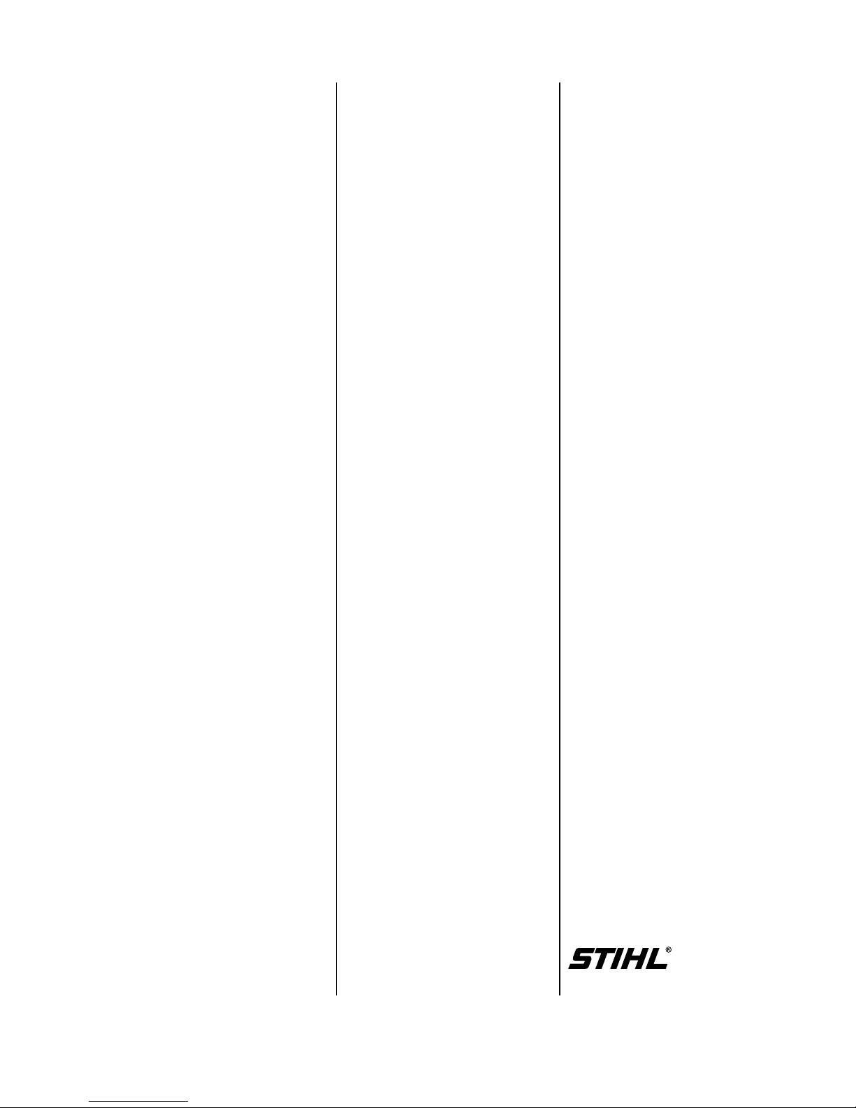
Servicing and repairs are made
considerably easier if the electric
saw is mounted to the assembly
stand (1) 5910 890 3100.
This enables the saw to be swivel-
led to the best position for the on-
going repair and leaves both
hands free.
It is secured with the sprocket co-
ver nut (after removing sprocket
cover). On the E 180 C, remove
the quick chain tensioner and the
secure saw to stand with an M8
nut.
Always use original STIHL
replacement parts.
They can be identified by the
STIHL part number,
the logo
and the STIHL parts symbol
The symbol may appear alone on
small parts.
1. INTRODUCTION
100RA001
1
VA
2E140,E160,E180

2.1 Motor E 140 E 160 E 180 C
Type: Universal motor
Rating (kW): 1.4 1.6 1.8
Rated voltage (V): 120; 230 230 120; 230
Frequency (Hz): 60 50 50 60 50
Rated current (A): 11.7 6.4 7.3 15,0 8.2
Fuse (slow-blowing) (A): 15 16 16 15 16
Overload protection: Thermal overload circuit breaker
Type of enclosure: IP 20
Class of protection: II
Coasting brake: Mechanical
2.2 Gear Drive
Type: Straight-toothed ring gear with pinion, single-stage
Output speed with
bar and chain,
off load (idle): 5900 rpm1) 6300 rpm 6900 rpm3)
at rated load: 5000 rpm2) 5400 rpm 5400 rpm4)
Lubrication: STIHL multipurpose grease
2.3 Cutting Attachment
Chain sprocket: 7-tooth 3/8" Picco
spur sprocket
Chain lubrication: Fully automatic, speed-controlled reciprocating oil pump
Oil tank capacity: 0.20 l (0.4 US pt)
1) 120 V : 6100 rpm
2) 120 V : 4900 rpm
3) 120 V : 6800 rpm
4) 120 V : 5000 rpm
2. SPECIFICATIONS
3

Plastoform screws are used in polymer components. These screws form a permanent thread when
they are installed for the first time. They can be removed and installed as often as necessary without
detrimentally affecting the strength of the screwed assembly, providing the specified tightening torque
is observed.
For this reason always use a torque wrench.
Fastener Thread For component Torque Remarks
size Nm lbf.ft
Self-tapping screw IS-B6.3x32 LH hand guard/motor housing 4.5 3.3
Slotted nut M5 L Drive pinion/rotor shaft 8.0 5.9 1)
Plastoform screw IS-P3x10 Cover plate/sprocket cover 1.0 0.75
Plastoform screw IS-P4.5x25 Commutator cover/motor housing 3.0 2.2
Plastoform screw IS-P4.5x45 Stator/motor housing (1200 W) 3.0 3.0
Plastoform screw IS-P4.5x55 Stator/motor housing (1400, 1600 W) 3.0 3.0
Plastoform screw IS-P4x19 Oil pump/gear housing 2.5 1.8
Plastoform screw IS-P4x19 Handle housing/motor housing 2.0 1.5
Plastoform screw IS-P4x19 Cable clamp/motor housing 1.5 1.1
Plastoform screw IS-P5x20 Spiked bumper/handle housing 4.0 3.0
Plastoform screw IS-P5x20 Gear housing/motor housing 3.0 2.2
Spline screw IS-M6x25 Brake band/gear housing 6.0 4.4
Use the following procedure to fit a ’P’ screw in an existing thread:
–PlacethePscrewintheholeandrotateitcounterclockwiseuntilitdropsdownslightly.
–Tightenthescrewclockwisetothespecifiedtorque.
This procedure ensures that the screw engages properly in the existing thread and does not form a new thread.
1) Secure slotted nut with Loctite 242.
Note: Screws/nuts secured with adhesive are easier to release if they are heated beforehand with a hot air blo-
wer (hairdryer).
Be careful with polymer components!
Power screwdriver speed settings for polymer: Plastoform screws max. 600 rpm,
DG screws max. 500 rpm
2.4 Tightening Torques
4

The trigger switch (1) is equipped
with a mechanical starting lockout
(interlock button) which helps pre-
vent unintentional switch-on.
The saws feature a thermal over-
load circuit breaker (3) to protect
the electric motor from mechanical
overload.
This overload circuit breaker inter-
rupts the power supply to the saw
if the operator continues cutting for
an extended period with an over-
tensioned chain, uses excessive
feed force, "lugs down" the motor
speed or if the chain is suddenly
stopped by being pinched in the
cut.
Before restarting the saw and con-
tinuing work it is necessary to pull
the guide bar out of the cut and
wait for a short period until the
overload circuit breaker has coo-
led down. The overload circuit
breaker can then be reset by pres-
sing in the button as far as
the stop.
This is not a fault. The remedy in
such a case is to work with less
feed effort. Under no circumstan-
ces should the overload circuit
breaker be bypassed, even if the
owner explicitly requests such a
modification.
Chain brake
The brake lever is unlatched when
the "Quickstop" chain brake is
activated, either manually or by
inertia. The power supply is inter-
rupted immediately by the chain
brake switch (4) and the spring-loa-
ded brake band is clamped around
the brake drum at the same in-
stant.
This causes the saw chain to be
brought to a standstill and locked
in position. The chain brake is
disengaged by moving the hand
guard toward the front handle.
Coasting brake
The coasting brake supplements
the chain braking system. It brings
the rotating chain to a standstill
when the operator releases the
trigger switch.
In the idle condition, an additional
spring clamps the brake band aro-
und the brake drum.
When the trigger switch is squee-
zed, the brake band is first disen-
gaged from the brake drum via a
linkage. Only then does the switch
close and start the motor.
3. WIRING DIAGRAM/DESCRIPTION
100RA002
2
3
2
1
2
1
1
2
K
1 2 3
4
5
6
5
7
VA
1Triggerswitch
2Capacitor(230Vonly)
3Overloadcircuitbreaker(E160,E180Conly)
4Chainbrakeswitch
5Brushholderwithcarbonbrush
6Rotor
7Stator
5

Important:Theelectricalsafetyof
thesawsshould be checkedafter
everyrepair by performingahigh-
voltage insulationtest.Testsof
thiskindmayonly be carriedout
by electricians or specially trained
personnel.
Alwaysunplugthemachinefrom
themainssupply.
-Remove the quickchain
tensioner,iffitted - see7.3.
•Unscrewnut.
-Removethechainsprocket
cover.
Models with quick chain
tensioner
•Take out screws(1).
•Removethespikedbumper(2).
Allmodels
-Removethechainsprocket -
see 6.1.
•Unscrewoilfillercapandremo-
ve togetherwithcapretainer.
•Takeoutthe screws.
-Removethehandlehousing.
•TakeouttheO-ring.
-Placeasocket(e.g.19mm)
underthehandlehousingsothat
it supportsthebearingbushfrom
outside.
•Usedrift(1)11118934700to
pressneedlesleeveoutof
bearingbush.
•Takeoutthe screws.
-Removethestrainreliefcable
clamp.
100RA005 VA
100RA008
1
VA
100RA004
2
1
1
VA
100RA003 VA
4. Removing and Installing Electrical Components
4.1 Connecting Cord
100RA007 VA
100RA006 VA
100RA009 VA
6

•Slackenoffthe screws.
-Pullthewiresoutoftheswitch.
•Pullcableprotectorofftheold
connectingcord.
Installation is a reversal of the
removalsequence.
-Slipthecableprotector,thinend
first,overthenewconnecting
cord.
•Checkthatcableprotectoris
correctlyseated.
-Fitthestrainreliefclamp
andtightenscrews to 1.5Nm
(1.1lbf.ft).
•Fit a newO-ring on gearhousing
pivotpin.
-Place a socket(e.g.19mm)
underthehandlehousingsothat
it supportsthebearingbushfrom
inside.
•Usepressarbor(1)4116893
7205toinstallneedlesleevein
thebearingbush.
•Checkcondition of sealingring
on oiltankandfit a newoneif
necessary - see9.1.
-Tightenthehandlehousing
mountingscrews to 2.0Nm
(1.5lbf.ft).
100RA014
1
VA
100RA011 VA
100RA012 VA
100RA015 VA
100RA010 VA
100RA013 VA
7

-Removethehandlehousing -
see4.1.
•Releasethescrews.
•Disconnectwires(1)of
connectingcord.
•Easethetriggerswitchslightly
awayfromthemotorhousing
anddisconnectthewires(2)
fromtheotherside of theswitch.
•Removethetriggerswitch(3).
Install in thereversesequence.
Important:Thewiresmust be re-
connected to the sameterminals,
see also 3.
-Removethetriggerswitch -
see 4.2.
•Cutthewireendferrulesoffthe
wires.
•Pullthecapacitoroutofthe
motorhousing.
Install in thereversesequence.
-Usewireendferrules to connect
wiresfrom overload circuit brea-
kerandstator to thecapacitor’s
wires.
Theoverloadcircuitbreaker
interruptsthepowersupplyto
protectthemotor in theeventof
mechanicaloverload(e.g.cutting
forextendedperiodwithexcessive
feedforce,suddenlystoppingthe
chain by pinching it in the cut).
Warning:Theoverload circuit
breakerandchainbrakeswitch
mustneverbe bypassed.
- Remove theoiltank - see9.1.
•Releasethescrew(1).
•Disconnectthewiresfromthe
switch.
•Cutwireendferrule(2)offthe
wires.
100RA019 VA
100RA016 VA
100RA017
1
2
3
VA
100RA020
1
2
VA
100RA018 VA
4.2 TriggerSwitch 4.3 Capacitor 4.4 OverloadCircuit Breaker
(230 V only) (E 160, E 180C)
8

•Pullofftheterminal.
•Pulloverloadcircuitbreakerout
of themotorhousing.
Install in thereversesequence.
•Usenewwireendferrule to join
the wire from the switch and
capacitorandpushintotheretai-
ners in themotorhousing.
-Remove the handlehousing -
see4.1.
•Removethewiresfromthe
brakeswitchterminals.
•Liftsnaphook(1) a littleand
thenpulloutthechainbrake
switch (2).
Install in thereversesequence.
100RA022 VA
100RA025 VA
1
2
100RA021 VA
100RA023 VA
100RA024 VA
4.5 ChainBrakeSwitch
9

•Takeoutthe screws.
-Removethecommutatorcover.
•Pullthewireofftheconnector
tag.
Pullthebrushholderforwardsand
take it away.
Note:Thefrictiongeneratedby
thecarbonbrushescausesthe
commutatorsurfacetoweargra-
duallyandeventuallyleavesse-
riousscores.Thesescorescause
increasedsparkingbetweenthe
carbonbrushesandcommutator.
If thecarbonbrushescanbere-
used, do notchangetheirinstalled
positions.
•Inspectcommutatorbeforefitting
thecarbonbrushesandreplace
therotor if necessary - see5.2.
-Checkthatthecarbonbrushmo-
vesfreely in thebrushholder.
•Fitthebrushholder so thatthe
topandbottomlugsslideintothe
slots in thehousing.
-Pushwireontoconnectortag.
-Refitcommutatorcoverand
tightenscrews to 3.0Nm
(2.2lbf.ft).
100RA027 VA
100RA031 VA
100RA028 VA
VA
100RA030
100RA029 VA
5. MOTOR
5.1 CarbonBrushes
10

-Removecarbonbrushes -
see 5.1.
-Removeoiltank - see9.1.
Removetheringgearandspur
gear - see6.2.
•Takeoutthescrew(1).
•Pulloffthehandguard(2).
•Pullwiresoffconnectortagson
chainbrake switch.
•Removescrewsfromgear
housing.
•Removethegearhousingand
pulltherotorout of thestatorat
thesametime.
•Disconnectthetensionsprings.
-Useahotairblower to heatthe
pinionmountingnut.
•Holdpinionsteadyandunscrew
slottedmountingnut in direction
of arrow(left-handthread).
•Prythepinionofftherotorshaft.
•Pulltherotoroutoftheball
bearing.
100RA032
1
2
VA
100RA034 VA
100RA033 VA
100RA024 VA
VA
100RA035
100RA036 VA
100RA037 VA
5.2 Rotor
VA
100RA038
11

•Examinebrakedrum(1)andfan-
wheel(2),replace if necessary -
see5.4.
Note:If brakedrumhas to be re-
placed,alsocheck the brakeband
-see8.1
- If brakedrum is still serviceable,
cleanandroughenitsfriction
facewithemerypaper or cloth
(grain size approx.120µm).
•Inspecttherotorcoreassembly
(1)fordamageandreplacethe
rotor if necessary.Thefanwheel
andballbearinghavetoberemo-
vedforthispurpose - see5.4
and5.3.
•Inspectthecommutator(2).
Note:In case of minorrunning
marks,dressthecommutator
withemerycloth. If running
marksaresevere,fitnewrotor.
•Examineballbearing(3)and
replace if necessary - see5.3.
Install in thereversesequence.
-Cleanthread of slottednutand
rotorstubwithstandardcommer-
cial,solvent-baseddegreasant
containingnochlorinatedor
halogenatedhydrocarbons -
see 10.2.
-Coatthread of slottednutwith
Loctite,see10.2,andscrew
slottednutintopinion.
•Holdpinionsteadyandtighten
downslottednut to 8.0Nm
(5.9lbf.ft).
•Attachsmallerspring(1)to
brakelever(2).
•Useassemblytube(2)1117890
0900tohooklargerspring(1)to
pivotpin.
-Torquedowngearhousing
screws to 3.0 Nm (2.2lbf.ft)and
screw on handguard to 4.5Nm
(3.3lbf.ft).
VA
2
1
100RA040
VA
100RA039
1 2
VA
100RA041
123
100RA043 VA
1 2
VA
100RA042
12

-Removetherotor - see5.2.
•Pulltheballbearingofftherotor
shaft.
•Removethenylonwasherand
inspect it. Refit it so that its flat
side is againstthecommutator.
-Heatballbearingtoapprox.
50°C(120°F)andpush it on as
far as stop.
Checkballbearing in gearhou-
sing.Ifballbearing is faulty, fit a
newgearhousing - see6.3.
-Installtherotor - see5.2.
-Remove the rotor - see5.2.
•Restfanwheelflange(seearrow)
on twoflatsteelbars(5x20x130
mm).
-Positionflatsteelbarswithrotor
inapress.
Note:Therotormusthangfreely.
•Useahotairblower to heatthe
hubarea of thebrakedrum.
VA
100RA045
VA
100RA044
VA
100RA047
100RA046 VA
100RA048 VA
5.3 Rotor Bearing 5.4 Fanwheel
13

•Holdtherotorandpress it outof
thebrakedrumandfanwheel.
-Cleanstub of rotorshaftwith
standardcommercial,solvent-
-baseddegreasantcontaining
no chlorinated or halogenated
hydrocarbons - see10.2.
•Pushthefanwheel,flangefirst,
ontotherotorshaft as far as it
willgo.
-Coattheflats on therotorshaft
withLoctite648 - see10.2.
•Fitthebrakedrum so thatthe
closedsidefacesthefanwheel.
-Standtherotorupright on a
socket(e.g. 19 mm)withthe
brakedrum at thebottom.
•Presstherotordownuntilthe
brakedrumlocatesagainstthe
shaftshoulder.
-Installtherotor - see5.2.
-Remove the rotor - see5.2.
•Pulltheairbaffleout of the
housing.
•Releasescrew(1) on switch(2).
•Pullwiresout of switch.Cutthe
endferrule(3)offtheend of the
wires.
•Takeoutthe screws.
-Pressstatorout of housing.
5.5 Stator
100RA053 VA
100RA055 VA
100RA052 VA
VA
100RA050 100RA049 VA
100RA051 VA
100RA054
2
3
1
VA
14

-Checkinsulation of fieldcoils.
Note:Install a newstatorif
insulation is damaged.
-Checkcondition of stator’sinner
runningsurface.Replacestatorif
necessary.
•Placestator in position.Use
screwdriver(1)59108902400to
pressstatorhome as far as stop.
Warning! Makesurewiresfor
carbonbrushesarenotpinched
in thisprocess.
-Fitstatormountingscrewsand
tighten to 3.0 Nm (3.0lbf.ft).
Installation is now a reversal of the
removalsequence.
-Remove the chainsprocket
cover - see4.1.
•Usescrewdriver to remove
E-clip (1).
•Removethewasher(2).
•Pullthechainsprocketoffthe
shaft.
•Removethewasher.
Install in thereversesequence.
-Remove the handlehousing -
see4.1.
•Pullthespurgearout of theoil
pump.
•Removewasher if it is still
sticking to thespurgear.
•Takethrustwasheroffthering
gearshaft.
6. CHAINDRIVE 6.2 RingGearandPinion
6.1 ChainSprocket
100RA056 VA
2 1
VA
100RA061 100RA059 VA
100RA058 VA
100RA065
1
VA
100RA057 VA
100RA060 VA
15

•Pullringgearoutofneedle
bearing in gearhousing.
•Takethethrustwasheroffthe
ringgearshaft.
•Checkcondition of needlebea-
ringingearhousingandreplace
if necessary.
-Checkcondition of needlebea-
ringinhandlehousingand
replace if necessary - see4.1.
-Removeringgear - see5.2.
•Onlyreplacepinion(1)andring
gear(2) as matchingset.
Install in thereversesequence.
-Coatringgearandwasherwith
lubricatinggrease - see10.2.
•Fitwasher in oilpump if it was
removedfromthespurgear.
- Remove therotor - see5.2
- Remove theoilpump - see9.2.
-Removechainbrake - see8.1.
•Liftsnaphook(1) a littleand
thenpulloutthechainbrake
switch (2).
•Pulltheoilstraineroffthestub.
Install in thereversesequence.
1
100RA071
2
VA
100RA063 VA
100RA062 VA
100RA070 VA
6.3 GearHousing
100RA064 VA
100RA067
1
2
VA
100RA085 VA
16

-Removethechainsprocket
cover - see4.1.
•Pullthecoverout of themotor
housing.
•Unscrewthetensioningnut(1)
fromtheadjustingscrew(2).
•Taketheadjustingscrewoutof
thecover(3).
Install in thereversesequence.
-Remove the chainsprocket
cover - see4.1.
•Takeoutthecompletechain
tensioner.
•Removethethrustpad(1).
•Rotatethespurgear(2)to
unscrewtheadjustingscrew(3)
fully from the tensionerslide(4).
•Pullthespurgear(1)out of the
cover (2).
•Pulloffthetensionerslide(1).
•Takeouttheadjustingscrew(2).
-Inspecttheteethonthespur
gearandadjustingscrew,
replacebothparts if necessary.
Install in thereversesequence.
Note:Coatteeth of adjusting
screwandspurgearwith
lubricatinggrease,see10.2,
beforerefitting.
7. CHAINTENSIONER
7.1 FrontChainTensioner 7.2 SideChainTensioner
100RA074
1 4 3 2
VA
100RA076
21
VA
100RA072 VA
100RA073 VA
100RA075
2 1
VA
143RA052 VA
12
3
17

•Pullouthingedhandle(1)of
wingnut(2).
•Unscrewthewingnutand
remove the chainsprocket
cover (3).
•Easethewingnutoutofthe
chainsprocketcover.
-Pushthewingnutintothechain
sprocketcoveruntil it snapsinto
position.
-Remove the gearhousing -
see 5.2.
-Removebrakedrum if necessary
-see5.4.
•Carefully pull the switch lever off
thepivot.
•Disconnectbrakerodfromthe
pawl.
•Prythepawlout of theswitch
lever.
•Takethetorsionspringoffthe
pawl.
Install in thereversesequence.
•Checkinstalledpositionof
torsionspring.
7.3 Quick Chain Tensioner 8. CHAIN BRAKE
8.1 Removal
100RA077
1
2
3
VA
100RA078 VA
100RA086 VA
100RA087 VA
100RA088 VA
100RA089 VA
100RA090 VA
18

-Removetheswitchlever -
see 8.1.
-Removetherotor - see5.2.
•Unhookbrakerodfrombrake
lever.
•Detachthesprings.
•Removethebrakebandfasten-
ing screw.
•Prythebrakebandoutofthe
gearhousing.
•Unhookbrakebandfrombrake
lever.
-Inspectbrakebandandfitnew
oneif:
-therearedefinitesigns of wear
(largeareas of insidediameter
and/orparts of outsidediameter)
and
-bandthicknessisless than 0.6
mm (0.025").
Important:Thebrakebandmust
mustnot be thinnerat anypoint.
- If the brakeband is stillservice-
able,cleanandroughenits
entirefrictionsurface(insideof
brakeband)withemerypaperor
cloth(grainsizeapprox.120µm).
•Prythecarrierandarticulated
leveroffthebearingpinandlift
themawaytogether.
-Pullthearticulatedleveroutoff
thecarrier.
•Removetheflatspring.
- Inspect allparts.Alwaysreplace
damagedparts.
-Cleanhousingrecess for chain
brakemechanism.
VA
100RA091
VA
100RA092
100RA093 VA
100RA094 VA
100RA095 VA
100RA097 VA
100RA098 VA
19
This manual suits for next models
2
Table of contents
Other Stihl Chainsaw manuals

Stihl
Stihl MS 441 C User manual

Stihl
Stihl MS 460 User manual

Stihl
Stihl MS 170 User manual

Stihl
Stihl 029, 039 User manual

Stihl
Stihl MS 462 User manual

Stihl
Stihl MS 201 TC-M User manual

Stihl
Stihl MS 290 User manual

Stihl
Stihl MS 210 User manual

Stihl
Stihl OILOMATIC User manual

Stihl
Stihl MS 250 User manual

Stihl
Stihl MS 311 User manual

Stihl
Stihl MS 193 User manual

Stihl
Stihl MSE 250 C User manual

Stihl
Stihl MS 201 C-M User manual

Stihl
Stihl MS 361 User manual

Stihl
Stihl MS 290 User manual

Stihl
Stihl MS 193 T User manual

Stihl
Stihl MS 362 C-M Manual

Stihl
Stihl MSA 120 C User manual

Stihl
Stihl MS 240 User manual