STINAR TV-550 Manual

sales@stinar.com |P651.454.5112 |F651.454.5143 |www.stinar.com
FLIGHT LINE TOW TRACTOR
OPERATION & MAINTENANCE MANUAL
MODEL: TV-550
RE V.07.2021

FLIGHT LINE TOW TRACTOR TV-550| 2
Table of Contents SECTION 1 | GENERAL INFORMATION & OPERATING
PROCEDURES � � � � � � � � � � � � � � � � � � � � � � � � � � � � � � 6
1�1 | Description � � � � � � � � � � � � � � � � � � � � � � � � � � � � 7
1.1.1 | Equipment Systems and Components . . . . . . . . . . . . . . . . . . . . 7
1.1.1.1 | Truck Chassis . . . . . . . . . . . . . . . . . . . . . . . . . . . . . . . . . . . . . . . . . . . . 7
1.1.1.2 | Modification to the cab include: . . . . . . . . . . . . . . . . . . . . . . . . . . 7
Figure 1.1.1 | Flight Line Tow Tractor, Model TV-550 . . . . . . . . . . . . . . . . . . .7
1.1.1.2 | Body. . . . . . . . . . . . . . . . . . . . . . . . . . . . . . . . . . . . . . . . . . . . . . . . . . . 9
1.1.1.3 | Pintle Hooks . . . . . . . . . . . . . . . . . . . . . . . . . . . . . . . . . . . . . . . . . . . . 9
1.1.2 | Electrical System . . . . . . . . . . . . . . . . . . . . . . . . . . . . . . . . . . . . . . . 9
1.1.2.1 | Relays and Circuit Breakers . . . . . . . . . . . . . . . . . . . . . . . . . . . . . . 10
1.1.2.2 | SAE J560b Receptacle . . . . . . . . . . . . . . . . . . . . . . . . . . . . . . . . . . 10
1.1.3 | Winterization Heaters . . . . . . . . . . . . . . . . . . . . . . . . . . . . . . . . . 11
Figure 1.1.2 | Electrical Schematic (Page 1 of 4) . . . . . . . . . . . . . . . . . . . . . .12
Figure 1.1.2 | Electrical Schematic (Page 2 of 4) . . . . . . . . . . . . . . . . . . . . . .13
Figure 1.1.2 | Electrical Schematic (Page 3 of 4) . . . . . . . . . . . . . . . . . . . . . .14
Figure 1.1.2 | Electrical Schematic (Page 4 of 4) . . . . . . . . . . . . . . . . . . . . . .15
1�2 | Operation � � � � � � � � � � � � � � � � � � � � � � � � � � � � 16
1.2.1 | Operating Controls and Indicators . . . . . . . . . . . . . . . . . . . . . . 16
1.2.1.1 | Cab Controls and Indicators . . . . . . . . . . . . . . . . . . . . . . . . . . . . 16
1.2.1.2 | Engine Hour Meter . . . . . . . . . . . . . . . . . . . . . . . . . . . . . . . . . . . . . 16
1.2.1.3 | Pintle Hooks . . . . . . . . . . . . . . . . . . . . . . . . . . . . . . . . . . . . . . . . . . . 17
1.2.1.4 | Winterization Heaters (Optional) . . . . . . . . . . . . . . . . . . . . . . . . . 18
1.2.1.5 | Receptacle (120 VAC Winterization Heaters Optional) . . . . . . 18
1.2.1.6 | Service Floodlight Controls . . . . . . . . . . . . . . . . . . . . . . . . . . . . . . 18
1.2.1.7 | Speed Limitier . . . . . . . . . . . . . . . . . . . . . . . . . . . . . . . . . . . . . . . . . 18
Figure 1.2.1.1 | Cab Controls and INdicators. . . . . . . . . . . . . . . . . . . . . . . . .19
Figure 1.2.1.3 | Rear Pintle Hooks . . . . . . . . . . . . . . . . . . . . . . . . . . . . . . . . . .19
1.2.2 | Pre-Operation Checks . . . . . . . . . . . . . . . . . . . . . . . . . . . . . . . . . 20
1.2.3 | Operating Procedures . . . . . . . . . . . . . . . . . . . . . . . . . . . . . . . . . 20
1.2.3.1 | Engine and Transmission . . . . . . . . . . . . . . . . . . . . . . . . . . . . . . . . 20
1.2.3.1.1 | Operating the Engine . . . . . . . . . . . . . . . . . . . . . . . . . . . . . . . . . 20
1.2.3.1.2 | Operating the Transmission . . . . . . . . . . . . . . . . . . . . . . . . . . . . 20
1.2.3.1.3 | Towing the FLTT . . . . . . . . . . . . . . . . . . . . . . . . . . . . . . . . . . . . . . . 20
1.2.4 | Operating Winterization Heaters (Optional). . . . . . . . . . . . . . 20
1.2.5 | Opening and Closing Procedure for Pintle Hooks . . . . . . . . . 21
1.2.6 | Description of Extendable Hitch Function. . . . . . . . . . . . . . . . 22
1.2.6.1 | For Non-nuclear Towing Only . . . . . . . . . . . . . . . . . . . . . . . . . . . . 22
1.2.6.2 | For Nuclear Towing. . . . . . . . . . . . . . . . . . . . . . . . . . . . . . . . . . . . . 22
1.2.7 | Adjusting Procedure for Rear Center Pintle Hook . . . . . . . . . 22
1.2.8 | Safety Requirements for Rear Center Pintle Hook . . . . . . . . 23
1.2.9 | Hook-up Procedure for Rear Center Pintle Hook . . . . . . . . . . 23
1.2.10 | Truck Lubrication and Fluids . . . . . . . . . . . . . . . . . . . . . . . . . . 24

FLIGHT LINE TOW TRACTOR TV-550| 3
Figure 1.2.1.10 | Truck Lubrication and Fluids. . . . . . . . . . . . . . . . . . . . . . . .25
1.3 | Specications & Capabilities � � � � � � � � � � � � � � � � � 26
1.3.1 | General Specications . . . . . . . . . . . . . . . . . . . . . . . . . . . . . . . . . 26
1.3.2 | Truck Cab and Chassis . . . . . . . . . . . . . . . . . . . . . . . . . . . . . . . . . 26
1.3.3 | Winterization Heaters (Optional) . . . . . . . . . . . . . . . . . . . . . . . 27
1.4 | Air Transportability Information � � � � � � � � � � � � � � 28
1.4.1 | General Specications . . . . . . . . . . . . . . . . . . . . . . . . . . . . . . . . . 28
1.4.2 | Dimension and Weight Data. . . . . . . . . . . . . . . . . . . . . . . . . . . . 28
1.4.3 | Removal and Relocation of Components. . . . . . . . . . . . . . . . . 29
1.4.4 | Preparing Tow Tractor for Air Transport . . . . . . . . . . . . . . . . . 29
1.4.5 | Loading Vehicle on to Aircraft . . . . . . . . . . . . . . . . . . . . . . . . . . 29
1.4.6 | Tie-Down Instructions . . . . . . . . . . . . . . . . . . . . . . . . . . . . . . . . . 30
1.4.6.1 | Tie-Down Devices . . . . . . . . . . . . . . . . . . . . . . . . . . . . . . . . . . . . . 30
1.4.6.2 | Tie-Down Locations . . . . . . . . . . . . . . . . . . . . . . . . . . . . . . . . . . . . 30
Figure 1.4.6.2 | Tie-Down Locations and Instructions . . . . . . . . . . . . . . . .31
SECTION 2 | MAINTENANCE & OVERHAUL � � � � � � � � � � � � � 32
2.1 | General � � � � � � � � � � � � � � � � � � � � � � � � � � � � � 32
2.2 | Truck Chassis-Cab � � � � � � � � � � � � � � � � � � � � � � � 32
2.3 | 120 VAC Winterization Heaters (Optional) � � � � � � � � � 32
2.4 | Spring Shackle U-bolts � � � � � � � � � � � � � � � � � � � � 32
2.5 | Front End Alignment Specications � � � � � � � � � � � � 32
2.6 | Tires and Wheels � � � � � � � � � � � � � � � � � � � � � � � 32
SECTION 3 | PARTS LIST � � � � � � � � � � � � � � � � � � � � � � � �34
3.1 | Manufacturer Identication List � � � � � � � � � � � � � � � 35
3.2 | Detailed Parts List � � � � � � � � � � � � � � � � � � � � � � � 36
3.2.1 | Understanding the Columns . . . . . . . . . . . . . . . . . . . . . . . . . . . 36
3.2.1.1 | Figure/Item No. . . . . . . . . . . . . . . . . . . . . . . . . . . . . . . . . . . . . . . . . 36
3.2.1.2 | Stinar Part No. . . . . . . . . . . . . . . . . . . . . . . . . . . . . . . . . . . . . . . . . . 36
3.2.1.3 | Description. . . . . . . . . . . . . . . . . . . . . . . . . . . . . . . . . . . . . . . . . . . . 36
3.2.1.4 | Vendor Code . . . . . . . . . . . . . . . . . . . . . . . . . . . . . . . . . . . . . . . . . 36
3.2.1.5 | QTY . . . . . . . . . . . . . . . . . . . . . . . . . . . . . . . . . . . . . . . . . . . . . . . . . . 36
3.2.2 | Instructions for Ordering Parts and Assemblies . . . . . . . . . . 36
PARTS ORDER FORM � � � � � � � � � � � � � � � � � � � � � � � � � � 37
Figure 3.3.1 | Flight Line Tow Tractor, Model TV-550 . . . . . . . . . . . . . . . . .38
Figure 3.3.2 | Cab Controls and Indicators . . . . . . . . . . . . . . . . . . . . . . . . . .41
Figure 3.3.3 | Rear View . . . . . . . . . . . . . . . . . . . . . . . . . . . . . . . . . . . . . . . . . .42
Figure 3.3.4 | Electrical System (Page 1 of 3) . . . . . . . . . . . . . . . . . . . . . . . .44
Figure 3.3.4 | Electrical System (Page 2 of 3) . . . . . . . . . . . . . . . . . . . . . . . .45
Figure 3.3.4 | Electrical System (Page 3 of 3) . . . . . . . . . . . . . . . . . . . . . . . .46
Figure 3.3.5 | AC Electrical System . . . . . . . . . . . . . . . . . . . . . . . . . . . . . . . . .48

FLIGHT LINE TOW TRACTOR TV-550| 4
1– General Information and Operating
Instructions
This publication provides operating and maintenance instructions, including
detailed part lists for the Flight Line Tow Tractor, Model TV-550. This
truck was manufactured by:
Stinar Corporation
3255 Sibley Memorial Highway
St. Paul, MN 55121 USA
Chapter 1 – Contains general information describing the unit and
recommended procedures for its operation, as well as specifications and
capabilities of the unit.
Chapter 2 - Provides information for maintaining the unit.
Chapter 3 – Contains a list of manufacturers and illustrated parts lists of
the assemblies, subassemblies, and systems within the unit.
Chapter 4 - Contains vendor data for overhaul and repair of major
vendor-manufactured components, which are installed on these units.
Definition of Terms
SAFETY ALERT SYMBOL – Look for this symbol to point out
important safety precautions.
DANGER: The word “DANGER” denotes a most serious specific
potential hazard. A forbidden practice should definitely be avoided in
connection with a serious hazard.
WARNING: The word “WARNING” is used to denote a specific potential
or hidden hazard which, if not avoided, has the potential for serious injury.
CAUTION: The word “CAUTION” is used to denote a general reminder
of good safety practices or to direct attention to unsafe practices. Following
safe behavioral practices consistent with operating and maintenance
instructions will help the operator and others avoid accident involvement.
NOTE: The word “NOTE” is used to denote something that can cause
minor machine damage, or poor performance if ignored.
IMPORTANT: The word “IMPORTANT” informs the reader of
something he needs to know to prevent minor machine damage if a certain
procedure is not followed.
General Safety:
- Do not rush
- Do not alter your machine
- Read and follow all warning labels. Replace any labels that are
missing or illegible.
- Check all controls and operating functions of the machine in a safe area
before starting work
This manual applies to the Flight
Line Tow Tractors built under
T.O. 36A10-3-54-1 dtd 28 Oct.
2004, supplied to Defense
Support Services
Safety Section

FLIGHT LINE TOW TRACTOR TV-550| 5
- Never allow unauthorized persons around machinery when performing
operation functions
- A fire extinguisher and first aid kit should be carried in the truck at all
times
Before Operation
1. Perform a general all-around visual inspection and equipment check of
the entire unit.
2. Check all markings and nameplates for legibility.
3. Perform any checks required by airport or airline regulations.
4. Always determine hydraulic oil level and fill tank to proper level with
all hydraulic cylinders fully retracted. Overfilling may occur if cylinders
are not retracted which may damage the system
5. If operating at night, check compartment lights for proper operation.
6. Check lights, horn, mirrors, wipers, safety belt, and all other safety
equipment for proper operation.
During Operation
Engine and Transmission
• To operate the engine, refer to the truck operator's manual for
recommended engine starting and operating procedures.
• Failure to follow towing procedure may result in transmission
damage. Please check the manufacturer’s recommendations before
towing your unit.
• These procedures are suggested general operating procedures. For
specific aircraft servicing, follow procedures specified by your
airline.
Emergency Shutdown Procedure
In case of emergency, this unit may be shut down by pressing the stop
switch on the unit. This stop switch is located at (location). To shut down
the unit, press the above switch and hold until truck engine stalls.
After Operation
- Stop engine and allow machine to come to a complete stop before
leaving the cab or allowing anyone near the unit.
- Remove ignition key when parked
Service Safety
- Do not clean, adjust or service this unit while it is in motion.
- Periodically check tightness of nuts and bolts, and check for loose,
worn or misaligned parts. Use only approved replacement parts.
- Any new components installed during repair must include the current
safety signs specified by Stinar Corp.

FLIGHT LINE TOW TRACTOR TV-550| 6
- Perform all work in accordance with authorized standard shop
practices.
- Perform no welding, cutting, patching, and such on any load bearing or
supporting structure. If such repairs are necessary, contact the
Engineering department of Stinar Corporation before making any
alterations.
- Do not mix hydraulic oils of different specifications. Oils may not be
compatible and could result in damage to hydraulic system
components.
- A thin oil film should be visible on the hydraulic cylinder shaft. A
steady drip of oil indicates a need for service.
- Should there be a hydraulic system associated with this unit, always
determine hydraulic oil level and fill tank to the proper level with all
hydraulic actuating cylinders fully retracted. Otherwise, damage may
occur to the tank when the system is operated.
- The hydraulic actuating cylinder exerts a very powerful force. Always
inspect any jammed components carefully for condition, distortion, and
other irregularities after the equipment has been jammed.
Your safety and the safety of those around you depend upon the operator
using care and good judgment in the operation of this unit. Know the
positions and functions of all controls before attempting to operate.
All equipment has limitations. Understand the speed, braking, steering,
stability and load characteristics of the unit before starting operation.
READ YOUR OPERATOR’S MANUAL!

FLIGHT LINE TOW TRACTOR TV-550| 7
The Stinar Flight Line Tow Tractor, Model TV-550, is a modified Ford
Model F-350 truck equipped to tow loaded cargo carts or trailers over
airport ramps and service roads
The vehicle has a towing capacity (draw bar pull or DBP) of 4500 pounds
(2,045 kilograms) for support equipment (SE). It tows aircraft (AC) up to
70,000 pounds or trailers up to 40,000 pounds on grades up to 2.5%. It is
capable of towing trailers (on grades up to 2.5%) from a stop to 10 MPH
(minimum) and aircraft from a stop to 5 MPH (minimum). It has a
minimum reverse speed of 2.5 MPH.
1.1.1 Equipment Systems and Components
The major operating systems and components of the Flight Line Tow
Vehicle are described in the paragraphs below. See Figure 1.1.1 for
locations of components.
1.1.1.1 Truck Chassis
The Tow Vehicle is built on a Ford F-350 chassis-cab and is powered by a
366 cubic inch (6.0 liter) 8-cylinder diesel engine. The transmission is a 5-
speed automatic. Most units have rear wheel drive. A few units have four
wheel drive. There is a receptacle box for Type A winterization heaters, and
a plug for Type C heaters.
The chassis has been shortened to a 98.5-inch (2502 mm) wheelbase. The
engine has been lowered by 2 degrees at the rear transmission mount, by
lowering the rear cross member. This was done to keep the angle of the
shortened drive shaft within OEM tolerances. Also, shims have been
installed under the rear leaf spring assemblies as part of the drive train
realignment.
Two double-faced signal lamps and an adjustable floodlight are mounted on
a light bar behind the cab. Some units may be equipped with an adjustable
spotlight on the driver's side, controlled from inside the cab at the driver's
position.
1.1.1.2 Modifications to the cab include:
-Beacon ON/OFF switch and indicator
-Heaters ON indicator (on type A winterized units)
-Floodlight ON/OFF switch
1.1 Description
FLIGHT LINE TOW TRACTOR TV-550| 8
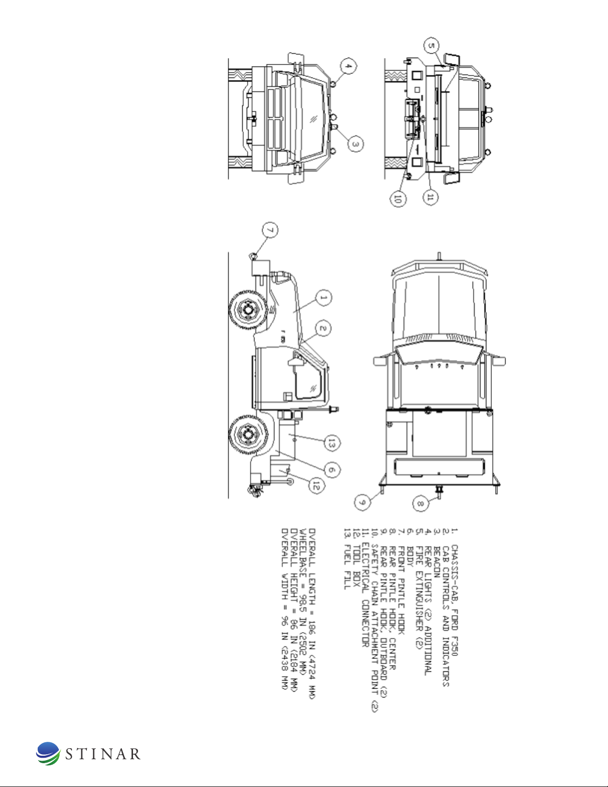
Figure 1.1.1 – Flight Line Tow Tractor, Model TV-550
FLIGHT LINE TOW TRACTOR TV-550| 9
1.1.1.2 Body
A special body is mounted aft of the cab over the rear wheels. A steel
toolbox with a lid is part of the body. Two 5 lb. Dry Chemical, Type 1,
Class 1, Size 5 fire extinguishers, in accordance with CID A-A-393, are
provided with a minimum UL rating of 2A:10B:C. They are located at the
left and right rear of the vehicle.
1.1.1.3 Pintle Hooks
There are three rear pintle hooks and one front pintle hook on each truck.
Component Description
Front Pintle Hook
Equipped with a retaining pin.
Rear Outboard Pintle
Hook (2)
Equipped with a retaining pin.
Rear Center Pintle
Hook
Extendable and height adjustable. Also
capable of swinging left and right.
Safety Chain
Attachment Point
(2)
5000-pound maximum shock load (each)
Trailer Emergency
Breakaway Cable
Hookup
Mates with NAS 1281C10 spring snap
hook
Electrical Connection SAE J560b receptacle
1.1.2 Electrical System
The electrical system is the OEM Ford 12-volt electrical system except for
the additions noted below.
Component Description
Flashing Amber
Beacon
Located on light bar. The control switch,
indicator, and flasher are installed in cab.
Rear Taillights
Duplicated on light bar.
Front Spotlight Located by driver's door on cab.
Rear Spotlight Located on light bar. Illuminates pintle
hook for night operation.
Trailer Lights
Receptacle
An SAE J560b electrical receptacle for
connecting trailer lights is located on the
rear bumper.
Speed Control
Module
The speed control module is located under
the instrument panel near the OEM truck
fuse panel.
NOTE : Winterized units
have a separate electrical
system for the heaters.
FLIGHT LINE TOW TRACTOR TV-550| 10
Component
Description
Heavy Duty Power
Module
Located in enclosure at rear of vehicle.
Provides power to trailer lights directly
from tow vehicle battery.
Power Control Relay
(K4)
Located in enclosure at rear of vehicle.
Isolates and powers stop lamps, 12 VDC
current to pin 4 of SAE J560b receptacle.
Fuse, 70 amp Located under hood near battery. Protects
the Main Power Relay (K3)
Main Power Relay
(K3)
This 75-amp relay powers and isolates
three Stinar added circuits from the Ford
OEM equipment.
1.1.2.1 Relays and Circuit Breakers
Relays and circuit breakers for Stinar-added electrical components are
located under the truck instrument panel behind the OEM fuse panel. These
include the following. See electrical schematic for functions.
Component Description
Relays Two SPDT relays (Relay 1 and Relay 2) for
the anti-restart circuit are located under
the dash behind the OEM truck fuse panel.
They prevent engaging the starter when
the engine is running.
Circuit Breaker, 25
ampere
This 25-ampere circuit breaker is for the
spotlights and beacon circuit.
Circuit Breaker, 15
ampere
This 15-ampere circuit breaker is for the
speed control module only.
Circuit Breaker, 10
ampere
This 10-ampere circuit breaker is for the
anti-restart relays.
Circuit Breaker, 20
ampere
This 20-ampere circuit breaker is for the
Auxiliary blue wire
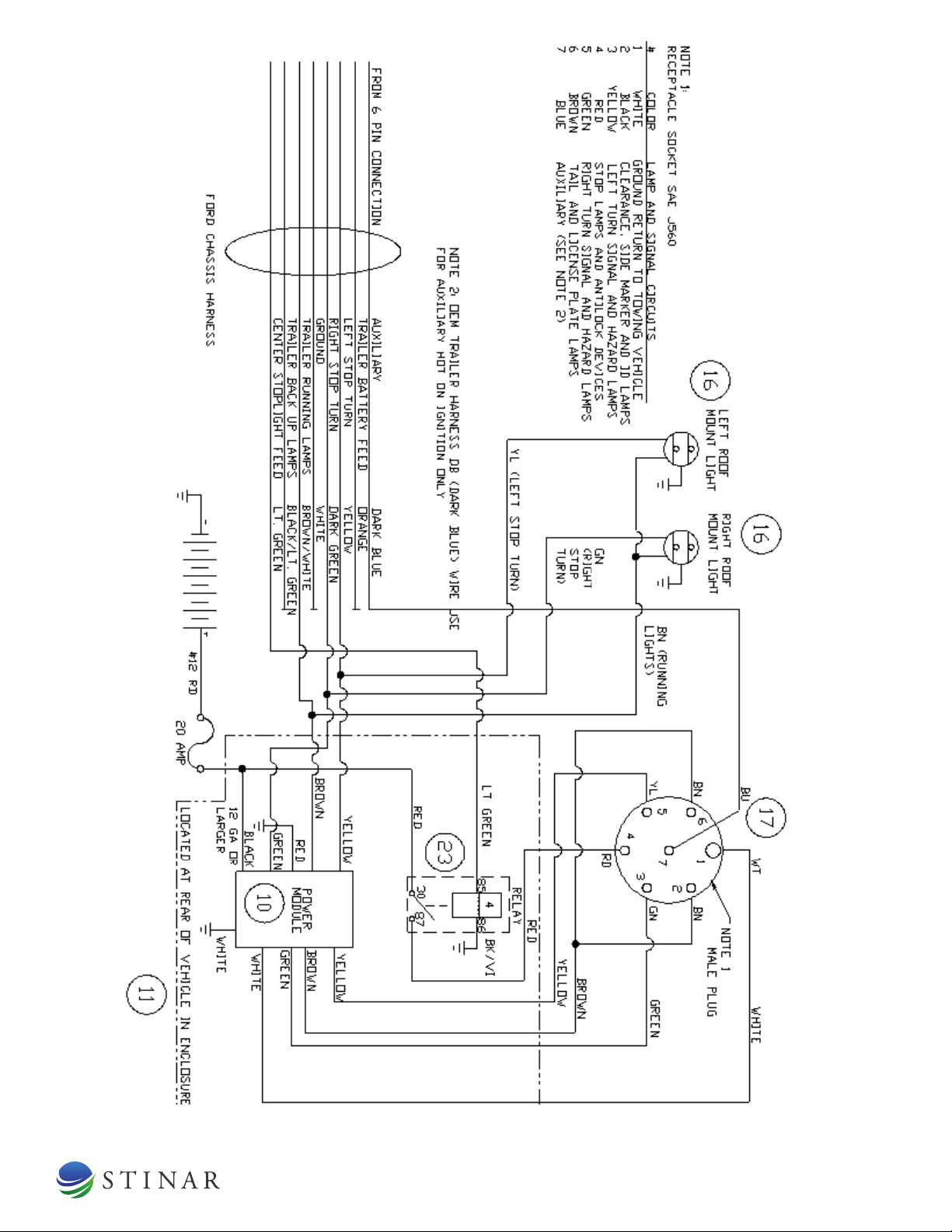
1.1.2.2 SAE J560b Receptacle
Use the following table for reference on the SAE J560b receptacle at the
rear of the vehicle.
Number Color Lamp and Signal Circuits
1 White Ground return to towing vehicle.
2
Black
Clearance, side marker and ID lamps
3
Yellow
Left turn signal and hazard lamps
4
Red
Stop lamps and antilock devices
5 Green Right turn signal and hazard lamps
6
Brown
Tail and license plate lamps
7 Blue Auxiliary

FLIGHT LINE TOW TRACTOR TV-550| 11
1.1.3 Winterization Heaters
All units have winterization heaters to allow their operation in cold climates.
All winterized type A units have a three-prong male slave receptacle for
receiving external power. Type A units also have a 25-foot connecting
cable, and provisions for storing the cable in the cab.
Component
Location
Type A, Storage to –65 degrees F, Starting to –40 degrees F
Engine Block Heater
Located in engine block.
Battery Warmer Located around truck battery
Fuel Preheater Located on frame rail.
Type C, Starting to –20 degrees F, Operation to +125 degrees F
Engine Block Heater Located in engine block.
Fuel Preheater Located on frame rail.
FLIGHT LINE TOW TRACTOR TV-550| 12
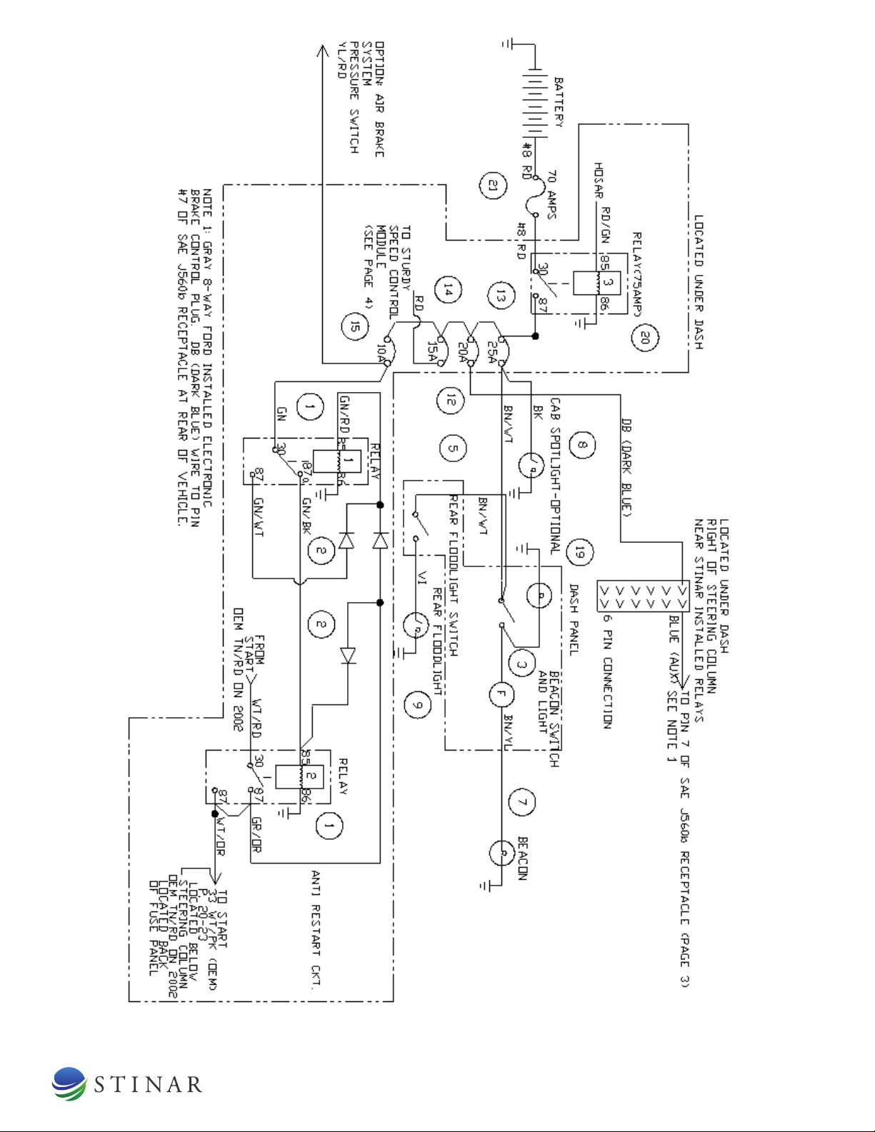
Figure 1.1.2 – Electrical Schematic (Page 1 of 4)
FLIGHT LINE TOW TRACTOR TV-550| 13
Figure 1.1.2 – Electrical Schematic (Page 2 of 4)
FLIGHT LINE TOW TRACTOR TV-550| 14
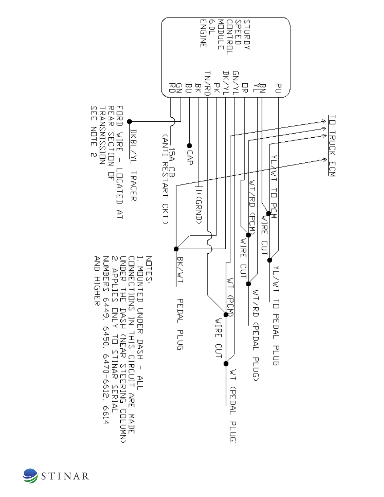
Figure 1.1.2 – Electrical Schematic (Page 3 of 4)

FLIGHT LINE TOW TRACTOR TV-550| 15
Figure 1.1.2 – Electrical Schematic (Page 4 of 4) (AC system)

FLIGHT LINE TOW TRACTOR TV-550| 16
Prior to operating the Flight Line Tow Tractor, all operators and
maintenance personnel should become thoroughly familiar with the
instructions given in this manual. No instructions listed in this section cover
driving the vehicle. The truck owner’s manual includes this information.
1.2.1 Operating Controls and Indicators
All controls for operating the unit are located in convenient places and are
clearly marked. A description of each control and indicator follows.
1.2.1.1 Cab Controls and Indicators (See Figure 1.2.1.1)
Component Description
Beacon ON/OFF
toggle switch Turns beacon on light bar on and off.
Beacon ON Indicator When illuminated, this amber light
indicates the beacon is on.
Floodlight ON/OFF
toggle switch
Turns floodlight on light bar on and off.
Winterization
Heaters ON
Indicator
When illuminated, this green light
indicates the winterization heaters are on.
Used on type A winterization units only.
1.2.1.2 Engine Hour Meter (See figure 1.2.1.2)
This function has now been incorporated into the Ford Chassis. Select this
function from the INFO menu to display the total accumulated running time
of the engine. Press in the selector knob to change from Odometer to Trip
Odometer until Engine Hours appears on the display.
Figure 1.2.1.2 Engine Hour Meter Display
1.2 Operation

FLIGHT LINE TOW TRACTOR TV-550| 17
1.2.1.3 Pintle Hooks (See Figure 1.2.1.3)
There are three pintle hooks at the rear of the truck, along with other safety
hardware and an electrical connector. There is one pintle hook at the front.
Component
Description
Front Pintle Hook Used for towing truck. The mount is
capable of withstanding 18000 pounds of
DBP. Mounted 18-1/2 inches above the
ground.
Outboard Rear Pintle
Hooks (2)
Capable of withstanding 6000 pounds of
DBP each. Mounted 18-1/2 inches above
the ground and 43.5 inches (plus 1.5
inches) outboard of vehicle center line.
Center Rear Pintle
Hook
Consists of a self-locking bar, which can
extend approximately 12 inches and swing
45 degrees to either side. Features four
height positions between 12 and 18-1/2
inches above the ground. Capable of
withstanding 6000 pounds of DBP
extended and 18000 pounds of DBP
retracted.
(2) Safety Chain
Attachment Points
Capable of withstanding a 5000-pound
shock load (each).
Trailer Emergency
Breakaway Cable
Mates with a NAS 1281C10 spring snap
hook
Electrical receptacle SAE J560b. Located within 14 inches of
center pintle hook.
Heavy Duty Power
Module
Provides power to trailer lights directly
from tow vehicle battery.
Power Control Relay
(K4)
Isolates and powers stop lamps, 12 VDC
current to pin 4 of SAE J560b receptacle.

FLIGHT LINE TOW TRACTOR TV-550| 18
1.2.1.4 Winterization Heaters (Optional)
Trucks designed to operate in cold climates have one of two different
winterization heater packages installed. Type A winterization is rated to –65
degrees F for storage and –40 degrees F for starting. Type C winterization is
rated to –20 degrees F for starting. The heaters operate any time the external
power supply line is plugged in. They have no ON/OFF switches.
Component
Description
Type A winterization
Engine Block Heater Electric heating element in engine block.
Keeps engine warm.
Battery Warmer Electric heating blanket around each truck
battery. Keeps each battery warm to
maintain adequate power level.
Fuel Heater Warms diesel fuel before it reaches engine
to ensure good fuel flow and good
combustion in the engine.
Type C winterization
Engine Block Heater Electric heating element in engine block.
Keeps engine warm.
Fuel Heater Warms diesel fuel before it reaches engine
to ensure good fuel flow and good
combustion in the engine.
1.2.1.5 Receptacle (120 VAC Winterization Heaters
Optional)
This receptacle is marked 120 VAC Input and is located at the front of the
truck. When connected to an external power cable, this receptacle provides
current to operate the winterization heaters. The receptacle is rated at 30
amps and 120 volts. It accepts a standard 30 amp, 30 pole, 3-wire locking
twist plug. The receptacle has a weatherproof lift cover. Only trucks with
type A winterization have this receptacle. Trucks with type C winterization
have a plug in the truck's front grille for heater power.
1.2.1.6 Service Floodlight Controls
The floodlight at the rear of the truck is controlled by a switch on the cab
dash. The floodlight by the cab is controlled by a switch on the floodlight.
1.2.1.7 Speed Limiter
A Sturdy Corporation ER-06 speed limiter (Stinar MPR number 509890)
works with the truck's electronic engine throttle control to limit maximum
vehicle speed to 40 MPH (plus 0, minus 3). This unit is located under the
cab dash to the right of the steering column, and does not need any service.
The "Service Engine Soon" light may illuminate when the accelerator is
held at full throttle due to the installation of the Sturdy speed control. This
condition does not require service. The vehicle's ability to operate safely is
not a concern unless the light is blinking or remains on continuously. See
the Owners' Guide.

FLIGHT LINE TOW TRACTOR TV-550| 19
Figure 1.2.1.1 – Cab Controls and Indicators
Figure 1.2.1.3 – Rear Pintle Hooks

FLIGHT LINE TOW TRACTOR TV-550| 20
1.2.2 Pre-Operation Checks
1. Check truck engine oil and coolant levels.
2. Perform an all-around visual inspection and equipment check of the
entire tow tractor.
3. If operating at night, check rear floodlight for proper operation.
4. Inspect chassis-cab in accordance with the guidelines of your air base.
5. Check lights, horn, mirrors, wipers, safety belt, and all other safety
equipment for proper operation.
1.2.3 Operating Procedures
1.2.3.1 Engine and Transmission
1.2.3.1.1 Operating the Engine
To operate the engine, refer to the Ford operator’s manual for recommended
engine starting and operating procedures.
A Sturdy speed control unit that works with the truck's electronically
controlled engine throttle limits maximum truck speed to 40 MPH (plus 0,
minus 3).
1.2.3.1.2 Operating the Transmission
The transmission is a 5-speed automatic. When in the drive position, the
transmission will shift automatically through all forward gears. Shifting
between drive, neutral, and reverse should be done when the engine idles.
1.2.3.1.3 Towing the FLTT
It is not possible to start the engine by towing the truck. Take extreme care
when towing the vehicle. Before towing or pushing a disabled vehicle,
disconnect the driveline or lift the drive wheels off the ground.
1.2.4 Operating Winterization Heaters (Optional)
1. Make sure the unit is parked. Operate the 120 VAC engine, battery, and
fuel line heater as follows:
2. Connect the power cord to the 120 VAC receptacle at the front of the
unit (Type A winterization) or the plug in the front grille (Type C units).
Connect the other end to a 120 VAC power source. The 120 VAC
heaters operate whenever the power cord is connected to facility power.
There are no ON/OFF switches.
3. Disconnect the power cord before moving the vehicle. Failure to do so
will damage the power cord and the vehicle.
CAUTION! Before placing
the unit into service, check fuel
level, engine crankcase oil, and
coolant levels.
CAUTION! Failure to
follow this procedure may
result in transmission damage.
NOTE Use the winterization
heaters whenever the truck is
operated in temperatures of
32°F (0°C) or lower.
CAUTION! Do not drive
unit without first disconnecting
heater power cord.
Table of contents


