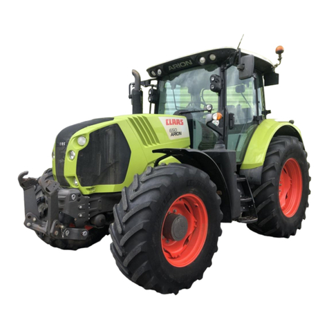
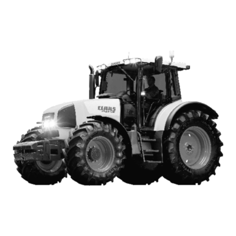
Claas AXION 840 CMATIC User manual

CLAAS KgaA mbH
Postfach 1163, 33426 Harsewinkel
Tel. +49 (0)5247 12-0
www.claas.com
00 11 185 590
TRAKTOR
DE - 11.07
Printed in France
AXION 840-820-810 CMATIC
Operator's manual

ABOUT THIS OPERATOR'S MANUAL
6543
This is the original operator's manual. It will simply be referred to as the "operator's manual" throughout this
document
This operator's manual complies with the regulations currently in force in the first country the tractor has been
delivered to.
This operator's manual contains the instructions for using, adjusting, servicing, cleaning and transporting the
tractor. It is essential to be familiar with all of these instructions in order to:
-Improve the performance of the tractor
-Increase the tractor's availability
-Extend the service life of the tractor
-Ensure the correct working conditions in terms of both safety and comfort
If any maintenance operations are missed or if the tractor is used incorrectly, the following is possible:
-An increased safety risk
-Premature wear of the tractor
-A reduction in tractor performance
-Loss of output and time
Have the tractor serviced regularly by an approved CLAAS distributor.
This operator's manual can be considered contractual. CLAAS has a policy of continuous technical improvement to
all its products, and therefore reserves the right to change without notice and at any time the details contained in
this operator's manual.
The description of the models contained in this operator's manual was established from technical specifications
known at the time this operator's manual was written. The operator's manual contains all of the equipment
(standard or optional) that exists for these models. The presence of this equipment in the tractor depends on the
tractor version and options chosen by the purchaser and the country of sale for this tractor.
Servicing operations during the warranty period are mandatory; failure to carry them out will nullify the contractual
warranty.
Failure to observe the instructions for use and maintenance of the tractor as described in this operator's manual
definitively excludes any possibility of recourse to the CLAAS warranty system.
The instruction and warning plates affixed to the tractor give important information about possible risks of use.
Following these instructions will guarantee your safety!
Front/rear tools have a separate operator's manual.
The CLAAS distribution network is available to respond to any questions that you may have relating to the content
of this operator's manual.
Important information concerning this operator's manual
Important information concerning this operator's manual appears at the end of the manual:
AXION 840-810 CMATIC - 02/2012 - en 3
Find manuals at http://best-manuals.com/search?&s=CLA-11210575

1 - Address of CLAAS company headquarters
2 - Phone number to call if necessary
3 - Address of CLAAS company website
4 - Reference of this operator's manual
5 - Designation of this operator's manual
6 - Language code for this operator's manual
7 - Publication date of this operator's manual
8 - Country where this operator's manual was printed
CLAAS KGaA mbH
Postfach 1163
33416 Harsewinkel
Tel. +49 (0)5247 12-0
www.claas.com
XX XXXX XXX X
OM XXXXX XXX
XX - XX/XXXX
Printed in France
6
8
7
5
4
3
1
2
000msn00gm
The reference, designation and publication date of this operator's manual also appear at the bottom of each page
of the operator's manual. The reference of the operator's manual should be quoted in any query concerning the
operator's manual and when ordering additional copies.
Classification into modules
The sections in this manual are categorised into modules, as far as the contents permit. The structure of these
modules is identical in each section.
The different product groups have different module structures. CLAAS always endeavours to retain these module
structures in each document.
Direction indications
Indications such as front, rear, right-hand and left-hand are always in the context of the direction of travel of the
tractor.
In the illustrations, the direction of travel may be indicated by a direction arrow.
Text and illustrations
Photos and graphics have been kept neutral wherever possible. If this is not the case, additional information is
added underneath the illustration.
Texts and illustrations have been kept neutral wherever possible. If this is not the case, the preceding subtitle takes
into account the differences.
Highlighting dangers and warnings
In the operator's manual, all points concerning personal safety and the safe use of the tractor are indicated by the
following symbols. Ensure that other users are also made aware of all safety advice.
4AXION 840-810 CMATIC - 02/2012 - en
Find manuals at http://best-manuals.com/search?&s=CLA-11210575

CAUTION
Instructions which must be strictly followed to prevent any risk of personal injury.
Important: Instructions which must be strictly followed to prevent damage to the tractor and its
environment.
Note: Instructions to be followed to ensure more efficient/suitable use of the tractor
Specific terminology
In this operator's manual, "tool" refers to any equipment hitched to the tractor, whether carried or towed.
Likewise, the term "risk zone" refers to all locations with an increased risk of accident.
-Around the tractor and the tools hitched to the tractor
-Between the tractor and the carried/towed tools
-In the deployment or movement area of the tools
Technical specifications
The technical specifications, dimensions and weights are provided on a non-binding basis. CLAAS reserves the
right to modify them as part of the technical development, subject to errors.
Optional and additional equipment
Optional equipment consists of tractor equipment variants. Different variants are available but only one can be
fitted at a time.
Additional equipment consists of tractor equipment variants which can be fitted as accessories but which are not
part of the tractor's standard equipment.
The two terms refer to the possible variants. Standard equipment and equipment variants may vary according to
the country.
AXION 840-810 CMATIC - 02/2012 - en 5
Find manuals at http://best-manuals.com/search?&s=CLA-11210575

VALIDITY OF THE INSTRUCTIONS
5542
This operator's manual is valid for the following tractors:
Type of tractor Tractor serial number
From To
AXION A3100050
The operator's manual describes the possible equipment for your tractor. Your tractor's equipment is listed in your
order confirmation.
6 AXION 840-810 CMATIC - 02/2012 - en
Find manuals at http://best-manuals.com/search?&s=CLA-11210575

UNITS
5639
The units used in this document are in line with international system of units:
Physical Unit Name Symbol of unity Multiples and sub-multi-
ples of the unit
Size Metre m mm - cm
Volume Cubic meter m³ cm³ - dm³
Liter l ml - cl
Angle Degree °
Time Second s
Minute min
Hour h
Linear speed Kilometer per hour km/h m/h
Rotation speed Revolution per minute 1/min
Weight Kilogram kg g
Forced Newton N
Torque Newton meter Nm
Pressure Pascal Pa
Power Watt W kW
Flow rate Liter per minute l/min
Temperature Degree Celsius °C
Power voltage Volt V mV
Electric intensity Ampere A mA
Resistor Ohm ΩkΩ
Sound level Bel B(A) dB(A)
The date format used in this document also complies with the international system:
Year-Month-Day Example: 2010-07-15
AXION 840-810 CMATIC - 02/2012 - en 7
Find manuals at http://best-manuals.com/search?&s=CLA-11210575

CHAPTER SYMBOLS
5618
REF CHAPTERS SYMBOLS
AIDENTIFICATION - CERTIFICATION - SAFETY
BCAB
CELECTRICAL SERVICES
DENGINE
ETRANSMISSION
FFRONT AXLE
GREAR EQUIPMENT
HFRONT EQUIPMENT
ICEBIS TERMINAL
JWHEELS AND TYRES
KCHARACTERISTICS
kg
mm l
LMAINTENANCE
MOPERATIONS THAT ARE MANDATORY UNDER THE GUARAN-
TEE
8 AXION 840-810 CMATIC - 02/2012 - en
Find manuals at http://best-manuals.com/search?&s=CLA-11210575

CONTENTS
A - IDENTIFICATION - CERTIFICATION - SAFETY
1 TRACTOR INFORMATION PLATE ....................................................................................... A. 2
2 TRACTOR POWER LABEL ................................................................................................... A. 4
3 MOTOR INFORMATION PLATE ........................................................................................... A. 5
4 CAB IDENTIFICATION PLATE ............................................................................................. A. 6
5 EUROPEAN REGULATION ................................................................................................... A. 7
6 SAFETY .................................................................................................................................. A. 8
6.1 SAFETY INSTRUCTIONS ........................................................................................................ A. 8
6.2 SAFETY STICKERS WITH WARNING PICTOGRAMS ......................................................... A. 23
B - CAB
1 OPERATING AND WORKING ENVIRONMENT ................................................................... B. 2
1.1 INSTRUMENTS AND CONTROLS (DRIVING POSITION) ...................................................... B. 2
1.2 INSTRUMENTS AND CONTROLS (PANEL) ........................................................................... B. 4
1.3 STOWAGE AND ACCESSORIES ............................................................................................ B. 5
2 LIGHTING, INDICATORS AND SAFETY .............................................................................. B. 6
2.1 DESCRIPTION ......................................................................................................................... B. 6
2.2 LOW/HIGH BEAMS AND HORN .............................................................................................. B. 7
2.3 WORKING LIGHTS AND ROTATING BEACON ...................................................................... B. 8
2.4 OVERHEAD LIGHT .................................................................................................................. B. 9
2.5 REAR VIEW MIRRORS ............................................................................................................ B. 9
3 STARTING CONTACT ......................................................................................................... B. 11
4 MULTIFUNCTION ARMREST ............................................................................................. B. 12
5 CAB SUSPENSION ............................................................................................................. B. 13
5.1 Z-ACTIV CAB .......................................................................................................................... B. 13
5.2 Z CAB ..................................................................................................................................... B. 14
6 SEATS .................................................................................................................................. B. 16
6.1 DRIVER'S SEAT ..................................................................................................................... B. 16
6.2 PASSENGER SEAT ............................................................................................................... B. 18
7 STEERING WHEEL ............................................................................................................. B. 20
8 INSTRUMENT PANEL ......................................................................................................... B. 21
8.1 DESCRIPTION ....................................................................................................................... B. 21
8.2 OPERATION ........................................................................................................................... B. 23
8.3 OPERATION ........................................................................................................................... B. 25
8.4 CALIBRATION ........................................................................................................................ B. 26
9 DISPLAY .............................................................................................................................. B. 28
9.1 CEBIS TERMINAL .................................................................................................................. B. 28
AXION 840-810 CMATIC - 02/2012 - en
Find manuals at http://best-manuals.com/search?&s=CLA-11210575

10 HINGED PANELS AND WINDOWS .................................................................................... B. 29
11 SIGHT ................................................................................................................................... B. 33
12 HEATING - VENTILATION - MANUAL AIR CONDITIONING ............................................. B. 34
12.1 DESCRIPTION ....................................................................................................................... B. 34
12.2 OPERATION ........................................................................................................................... B. 34
13 HEATING/VENTILATION/AUTOMATIC CLIMATE CONTROL .......................................... B. 39
13.1 DESCRIPTION ....................................................................................................................... B. 39
13.2 OPERATION ........................................................................................................................... B. 39
C - ELECTRICAL SYSTEM
1 CHARACTERISTICS ............................................................................................................. C. 2
2 TRAILER/IMPLEMENT LIGHT SOCKET .............................................................................. C. 3
3 ELECTRIC CABINET SUPPLY SOCKET ............................................................................. C. 5
4 EVENT COUNTER SOCKET ................................................................................................. C. 6
5 ISO SOCKET .......................................................................................................................... C. 7
6 ISOBUS SOCKET .................................................................................................................. C. 8
7 PROVISION FOR THE INSTALLATION OF A CONTROL CASING IN THE CAB ............... C. 9
7.1 FITTING BOX MOUNTING ....................................................................................................... C. 9
7.2 CABLE ROUTING ..................................................................................................................... C. 9
8 BATTERY ............................................................................................................................. C. 10
8.1 BATTERY COMPARTMENT .................................................................................................. C. 10
8.2 BATTERY MASTER SWITCH ................................................................................................ C. 11
9 FUSES AND RELAYS ......................................................................................................... C. 12
9.1 RECOMMENDATIONS ........................................................................................................... C. 12
9.2 CAB-MOUNTED SERVICES FUSE BOX ............................................................................... C. 12
9.3 CAB TOP FUSE BOX ............................................................................................................. C. 15
9.4 PRIMARY SERVICES FUSE BOX ......................................................................................... C. 18
D - ENGINE
1 CHARACTERISTICS ............................................................................................................. D. 2
2 DISPLAYS .............................................................................................................................. D. 5
2.1 INSTRUMENT PANEL .............................................................................................................. D. 5
2.2 CEBIS TERMINAL .................................................................................................................... D. 5
3 SAFETY .................................................................................................................................. D. 6
3.1 OPERATION ............................................................................................................................. D. 6
3.2 CEBIS TERMINAL .................................................................................................................... D. 6
3.3 INSTRUMENT PANEL .............................................................................................................. D. 6
3.4 RECOMMENDATIONS ............................................................................................................. D. 6
4 ENGINE HOOD ...................................................................................................................... D. 8
4.1 ONE-PIECE HOOD .................................................................................................................. D. 8
4.2 SIDE PANELS .......................................................................................................................... D. 8
AXION 840-810 CMATIC - 02/2012 - en
Find manuals at http://best-manuals.com/search?&s=CLA-11210575

5 ENGINE CONTROL ............................................................................................................. D. 10
5.1 STARTING THE ENGINE ....................................................................................................... D. 10
5.2 USING THE ACCELERATOR PEDAL AND LEVER .............................................................. D. 13
5.3 STOPPING THE ENGINE ...................................................................................................... D. 16
6 CLAAS POWER MANAGEMENT ....................................................................................... D. 17
7 FUEL .................................................................................................................................... D. 18
7.1 RECOMMENDATIONS ........................................................................................................... D. 18
7.2 BLEEDING AIR FROM THE INJECTION SYSTEM ............................................................... D. 19
E - TRANSMISSION
GEARBOX
1 CHARACTERISTICS .............................................................................................................. E. 4
2 DISPLAY ............................................................................................................................... E. 5
3 SAFETY .................................................................................................................................. E. 6
3.1 REVERSER NEUTRAL ............................................................................................................. E. 6
3.2 TRANSMISSION NEUTRAL ..................................................................................................... E. 6
3.3 ENGINE ANTI-STALL ............................................................................................................... E. 7
3.4 PROTECTION OF MECHANICAL PARTS ............................................................................... E. 8
4 STARTING THE TRACTOR ................................................................................................... E. 9
4.1 CLUTCH .................................................................................................................................... E. 9
4.2 SELECTION OF MOVEMENT DIRECTION ........................................................................... E. 10
4.3 ACTIVE STOP ........................................................................................................................ E. 11
5 BASIC OPERATION ............................................................................................................ E. 12
6 ADVANCED DRIVING .......................................................................................................... E. 14
6.1 OPERATION ........................................................................................................................... E. 14
6.2 AUTOMATIC MODE ............................................................................................................... E. 16
6.3 DRIVESTICK MODE ............................................................................................................... E. 20
6.4 MANUAL ................................................................................................................................. E. 24
6.5 SPEED RANGES .................................................................................................................... E. 29
6.6 MAXIMUM SPEEDS AND SET SPEEDS ............................................................................... E. 30
6.7 ACCELERATION .................................................................................................................... E. 34
6.8 DROOP ................................................................................................................................... E. 35
6.9 DEGRADED MODE ................................................................................................................ E. 36
AXION 840-810 CMATIC - 02/2012 - en

REAR AXLE
1 CHARACTERISTICS ............................................................................................................ E. 38
2 DISPLAY ............................................................................................................................. E. 40
3 PROTECTION OF MECHANICAL PARTS .......................................................................... E. 41
3.1 OPERATION ........................................................................................................................... E. 41
3.2 INSTRUMENT PANEL ............................................................................................................ E. 41
3.3 CEBIS TERMINAL .................................................................................................................. E. 41
4 DIFFERENTIAL LOCK ......................................................................................................... E. 42
4.1 RECOMMENDATIONS ........................................................................................................... E. 42
4.2 OPERATION ........................................................................................................................... E. 42
4.3 AUTOMATIC MODE ............................................................................................................... E. 42
4.4 PERMANENT MODE .............................................................................................................. E. 44
5 BRAKES ............................................................................................................................... E. 45
5.1 SERVICE BRAKES ................................................................................................................. E. 45
5.2 HANDBRAKE (AUXILIARY AND PARKING BRAKE) ............................................................. E. 45
6 TRAILER BRAKE ................................................................................................................. E. 48
6.1 HYDRAULIC BRAKE .............................................................................................................. E. 48
6.2 PNEUMATIC BRAKE .............................................................................................................. E. 49
F - FRONT AXLE
1 CHARACTERISTICS .............................................................................................................. F. 2
2 PROTECTION OF MECHANICAL PARTS ............................................................................ F. 4
2.1 OPERATION ............................................................................................................................. F. 4
2.2 INSTRUMENT PANEL .............................................................................................................. F. 4
2.3 CEBIS TERMINAL .................................................................................................................... F. 4
3 FRONT AXLE ENGAGEMENT .............................................................................................. F. 5
3.1 OPERATION ............................................................................................................................. F. 5
3.2 AUTOMATIC MODE ................................................................................................................. F. 5
3.3 PERMANENT MODE ................................................................................................................ F. 6
4 DIFFERENTIAL LOCK ........................................................................................................... F. 8
4.1 RECOMMENDATIONS ............................................................................................................. F. 8
4.2 OPERATION ............................................................................................................................. F. 8
4.3 AUTOMATIC MODE ................................................................................................................. F. 8
4.4 PERMANENT MODE .............................................................................................................. F. 10
5 SUSPENDED FRONT AXLE ................................................................................................ F. 11
5.1 OPERATION ........................................................................................................................... F. 11
5.2 FIXED MODE .......................................................................................................................... F. 11
5.3 AUTOMATIC MODE ............................................................................................................... F. 12
AXION 840-810 CMATIC - 02/2012 - en

G - REAR EQUIPMENT
HYDRAULIC SYSTEMS
1 CHARACTERISTICS ............................................................................................................. G. 4
2 AUXILIARY SPOOL VALVES ............................................................................................... G. 5
2.1 ASSOCIATION BETWEEN CONTROLS/REAR PRESSURE CONNECTORS ....................... G. 5
2.2 PRESSURE CONNECTORS ................................................................................................... G. 7
2.3 CONTROLS ............................................................................................................................ G. 10
2.4 SAFETY .................................................................................................................................. G. 11
2.5 START UP .............................................................................................................................. G. 11
2.6 LINEAR CONTROLS .............................................................................................................. G. 13
2.7 JOYSTICK .............................................................................................................................. G. 13
2.8 EXTERNAL CONTROLS ........................................................................................................ G. 15
2.9 MANAGEMENT OF ELECTROHYDRAULIC SPOOL VALVES ............................................. G. 15
3 POWER BEYOND ................................................................................................................ G. 19
3.1 DESCRIPTION ....................................................................................................................... G. 19
3.2 OPERATION ........................................................................................................................... G. 19
3.3 OPERATION ........................................................................................................................... G. 19
4 STATIONARY WORKING ................................................................................................... G. 20
REAR LIFT
1 CHARACTERISTICS ........................................................................................................... G. 22
2 CONTROLS ......................................................................................................................... G. 23
3 DISPLAY .............................................................................................................................. G. 25
4 SAFETY ............................................................................................................................... G. 26
4.1 PROTECTION OF MECHANICAL PARTS ............................................................................. G. 26
4.2 WARNING LIGHT ................................................................................................................... G. 26
4.3 CEBIS TERMINAL .................................................................................................................. G. 26
4.4 ROAD TRANSPORT SAFETY ............................................................................................... G. 26
5 USING THE LINKAGE ......................................................................................................... G. 28
6 MODE SELECTION ............................................................................................................. G. 29
7 POSITION CONTROL .......................................................................................................... G. 30
8 FORCE CONTROL .............................................................................................................. G. 31
9 UPPER LIMIT ....................................................................................................................... G. 33
10 LOWERING SPEED ............................................................................................................. G. 34
11 TRANSPORT DAMPER ....................................................................................................... G. 35
12 ACTIVE WHEEL SLIP MANAGEMENT .............................................................................. G. 36
12.1 OPERATION ........................................................................................................................... G. 36
12.2 ADJUSTMENT ........................................................................................................................ G. 36
12.3 OPERATION ........................................................................................................................... G. 37
AXION 840-810 CMATIC - 02/2012 - en

13 EXTERNAL CONTROLS ..................................................................................................... G. 38
13.1 OPERATION ........................................................................................................................... G. 38
13.2 OPERATION ........................................................................................................................... G. 38
REAR POWER TAKE-OFF
1 CHARACTERISTICS ........................................................................................................... G. 42
2 RECOMMENDATIONS ........................................................................................................ G. 43
3 CONTROLS ......................................................................................................................... G. 44
4 DISPLAY ............................................................................................................................. G. 45
5 PTO SPEED SELECTION ................................................................................................... G. 46
6 OPERATION ........................................................................................................................ G. 47
7 EXTERNAL CONTROLS ..................................................................................................... G. 48
8 OPERATION ........................................................................................................................ G. 49
9 PTO AUTOMATION ............................................................................................................. G. 50
9.1 OPERATION ........................................................................................................................... G. 50
9.2 MANUAL ADJUSTMENT ........................................................................................................ G. 50
9.3 CEBIS PANEL ADJUSTMENT .............................................................................................. G. 51
10 POWER TAKE-OFF END FITTING ..................................................................................... G. 52
11 CONNECTING IMPLEMENTS TO THE POWER TAKE-OFF ............................................. G. 53
12 STATIONARY WORKING ................................................................................................... G. 54
REAR HITCH
1 CHARACTERISTICS ........................................................................................................... G. 56
2 RECOMMENDATIONS ........................................................................................................ G. 58
3 ADJUSTABLE LINKS .......................................................................................................... G. 60
4 UPPER LINK ........................................................................................................................ G. 61
4.1 MECHANICAL UPPER ROD .................................................................................................. G. 61
4.2 UPPER TOP LINKAGE .......................................................................................................... G. 61
5 AUTOMATIC HOOKS .......................................................................................................... G. 62
6 STABILISERS ...................................................................................................................... G. 64
6.1 OPERATION ........................................................................................................................... G. 64
6.2 MECHANICAL STABILISERS ................................................................................................ G. 64
6.3 SELF-LOCKING STABILISERS ............................................................................................. G. 64
AXION 840-810 CMATIC - 02/2012 - en

7 DRAW BAR COUPLINGS ................................................................................................... G. 65
8 SWINGING DRAWBAR ....................................................................................................... G. 67
9 TOW HOOK ......................................................................................................................... G. 69
10 AUTOMATIC PICK-UP HITCH ............................................................................................ G. 70
H - FRONT EQUIPMENT
HYDRAULIC SYSTEMS
1 CHARACTERISTICS ............................................................................................................. H. 4
2 PRESSURE CONNECTORS ................................................................................................. H. 5
2.1 RECOMMENDATIONS ............................................................................................................. H. 5
2.2 OPERATION ............................................................................................................................. H. 5
2.3 FREE RETURN TO THE TANK ................................................................................................ H. 6
3 SAFETY .................................................................................................................................. H. 7
3.1 PROTECTION OF MECHANICAL PARTS ............................................................................... H. 7
3.2 CEBIS TERMINAL .................................................................................................................... H. 7
4 FRONT PRESSURE TAPS CONTROLLED BY SPOOL VALVE 3 ....................................... H. 8
4.1 DESCRIPTION ......................................................................................................................... H. 8
4.2 CONTROLS .............................................................................................................................. H. 8
4.3 PRELIMINARY OPERATIONS ................................................................................................. H. 9
4.4 OPERATION ............................................................................................................................. H. 9
5 FRONT PRESSURE TAPS CONTROLLED BY SPOOL VALVE 7 ..................................... H. 11
5.1 DESCRIPTION ....................................................................................................................... H. 11
5.2 CONTROLS ............................................................................................................................ H. 11
5.3 PRELIMINARY OPERATIONS ............................................................................................... H. 12
5.4 OPERATION ........................................................................................................................... H. 13
6 FRONT PRESSURE TAPS CONTROLLED BY SPOOL VALVES 7 AND 8 ...................... H. 15
6.1 DESCRIPTION ....................................................................................................................... H. 15
6.2 CONTROLS ............................................................................................................................ H. 15
6.3 PRELIMINARY OPERATIONS ............................................................................................... H. 16
6.4 OPERATION ........................................................................................................................... H. 16
7 MANAGEMENT OF ELECTROHYDRAULIC SPOOL VALVES ......................................... H. 19
FRONT LINKAGE
1 CHARACTERISTICS ........................................................................................................... H. 22
2 FRONT LINKAGE CONTROLLED BY SPOOL VALVE 1 ................................................... H. 23
2.1 CONTROLS ............................................................................................................................ H. 23
2.2 SAFETY .................................................................................................................................. H. 24
2.3 PRELIMINARY OPERATIONS ............................................................................................... H. 25
2.4 OPERATION ........................................................................................................................... H. 26
2.5 EXTERNAL CONTROLS ........................................................................................................ H. 28
AXION 840-810 CMATIC - 02/2012 - en

3 TRANSPORT DAMPER ....................................................................................................... H. 29
4 FRONT LINKAGE CONTROLLED BY SPOOL VALVE 6 ................................................... H. 30
4.1 CONTROLS ............................................................................................................................ H. 30
4.2 SAFETY .................................................................................................................................. H. 31
4.3 PRELIMINARY OPERATIONS ............................................................................................... H. 32
4.4 OPERATION ........................................................................................................................... H. 33
4.5 EXTERNAL CONTROLS ........................................................................................................ H. 35
5 POSITION CONTROL .......................................................................................................... H. 36
5.1 DISPLAY ................................................................................................................................ H. 36
5.2 DESCRIPTION OF ADJUSTMENTS ...................................................................................... H. 37
5.3 ACTIVATION OF POSITION CONTROL ................................................................................ H. 37
5.4 UPPER LIMIT ADJUSTMENT ................................................................................................ H. 38
5.5 ADJUSTMENT OF THE BOTTOM STOP .............................................................................. H. 38
5.6 RAISING SPEED ADJUSTMENT ........................................................................................... H. 39
5.7 RATE OF DESCENT ADJUSTMENT ..................................................................................... H. 39
5.8 USING THE POSITION CONTROL ........................................................................................ H. 40
6 3-POINT HITCH .................................................................................................................... H. 42
6.1 LOWER LINKS ....................................................................................................................... H. 42
6.2 UPPER LINK ........................................................................................................................... H. 43
6.3 HITCHING AND UNHITCHING THE TOOL ........................................................................... H. 43
AXION 840-810 CMATIC - 02/2012 - en

FRONT POWER TAKE-OFF
1 CHARACTERISTICS ........................................................................................................... H. 48
2 DISPLAY ............................................................................................................................. H. 49
3 RECOMMENDATIONS ........................................................................................................ H. 50
4 FRONT POWER TAKE-OFF ENGAGEMENT ..................................................................... H. 52
5 STOP OF THE FRONT POWER TAKE-OFF ....................................................................... H. 53
FRONT LOADER
1 FITTING A FRONTAL LOADER ADAPTATION FRAME .................................................... H. 56
2 OPERATION ........................................................................................................................ H. 58
I - CEBIS TERMINAL
USING THE CEBIS TERMINAL
1 DESCRIPTION ......................................................................................................................... I. 4
2 OPERATION ............................................................................................................................ I. 5
3 OPERATION ............................................................................................................................ I. 6
4 MULTIFUNCTION DISPLAY ................................................................................................... I. 7
4.1 OPERATION .............................................................................................................................. I. 7
4.2 WORK SCREEN ........................................................................................................................ I. 8
4.3 ROAD SCREEN ....................................................................................................................... I. 11
5 DIRECT ACCESS .................................................................................................................. I. 14
5.1 OPERATION ............................................................................................................................ I. 14
5.2 OPERATION ............................................................................................................................ I. 15
6 MALFUNCTIONS ................................................................................................................... I. 16
6.1 OPERATION ............................................................................................................................ I. 16
6.2 WARNINGS .............................................................................................................................. I. 16
6.3 WARNING ................................................................................................................................ I. 17
6.4 INFORMATION ........................................................................................................................ I. 19
6.5 ICON ........................................................................................................................................ I. 20
7 MENU ..................................................................................................................................... I. 21
7.1 MAIN MENU ............................................................................................................................. I. 21
7.2 TRANSMISSION ...................................................................................................................... I. 22
7.3 LIFT .......................................................................................................................................... I. 24
7.4 HYDRAULICS .......................................................................................................................... I. 25
7.5 ON BOARD COMPUTER ......................................................................................................... I. 26
7.6 CLAAS SEQUENCE MANAGEMENT ...................................................................................... I. 29
7.7 PREVIEWING A CLAAS SEQUENCE MANAGEMENT SEQUENCE IN REAL TIME ............. I. 30
AXION 840-810 CMATIC - 02/2012 - en

ON BOARD COMPUTER
1 OPERATION .......................................................................................................................... I. 32
2 GENERAL PERFORMANCE ................................................................................................. I. 33
2.1 OPERATION ............................................................................................................................ I. 33
2.2 SELECTING INFORMATION FOR DISPLAY IN THE PROGRAMMABLE WINDOW ............. I. 34
2.3 COUNTER RESETTING .......................................................................................................... I. 34
3 PLOT MANAGEMENT ........................................................................................................... I. 35
3.1 OPERATION ............................................................................................................................ I. 35
3.2 COMPUTER START/SHUT DOWN ......................................................................................... I. 36
3.3 PLOT MANAGEMENT EDITOR ............................................................................................... I. 37
4 IMPLEMENT SETTINGS ....................................................................................................... I. 39
4.1 WORKING WIDTH ................................................................................................................... I. 39
4.2 COUNTING MODE ................................................................................................................... I. 39
4.3 SELECTING THE THEORETICAL OR ACTUAL SPEED ........................................................ I. 40
4.4 TOOL MANAGEMENT ............................................................................................................. I. 40
5 MAINTENANCE ..................................................................................................................... I. 46
5.1 MAINTENANCE COUNTER ..................................................................................................... I. 46
5.2 LIST OF ACTIVE DEFECTS .................................................................................................... I. 47
5.3 GEARBOX OIL TEMPERATURE ............................................................................................. I. 48
6 F1, F2, F3 AND F4 FUNCTION CONTACTS ........................................................................ I. 49
6.1 OPERATION ............................................................................................................................ I. 49
6.2 ADJUSTMENT ......................................................................................................................... I. 49
7 CEBIS .................................................................................................................................... I. 53
7.1 BRIGHTNESS .......................................................................................................................... I. 53
7.2 LANGUAGES AND UNITS ....................................................................................................... I. 55
7.3 DATE AND TIME ...................................................................................................................... I. 56
CLAAS SEQUENCE MANAGEMENT
1 OPERATION .......................................................................................................................... I. 58
2 OPERATION .......................................................................................................................... I. 59
3 CONTROLS ........................................................................................................................... I. 60
3.1 DESCRIPTION ......................................................................................................................... I. 60
4 SAFETY ................................................................................................................................. I. 61
4.1 PROTECTION OF MECHANICAL PARTS .............................................................................. I. 61
5 LAUNCHING A SEQUENCE ................................................................................................. I. 62
5.1 OPERATION ............................................................................................................................ I. 62
5.2 OPERATION ............................................................................................................................ I. 64
AXION 840-810 CMATIC - 02/2012 - en

6 SAVING A SEQUENCE ......................................................................................................... I. 68
7 INTERRUPTING A SEQUENCE ............................................................................................ I. 71
7.1 TO RESUME THE CURRENT SEQUENCE, PRESS THE SAME CONTACT ........................ I. 71
7.2 CANCELLING A PAUSED SEQUENCE .................................................................................. I. 71
7.3 CANCELLING AN ONGOING SEQUENCE ............................................................................. I. 72
7.4 CANCELLING ONGOING ACTIONS ....................................................................................... I. 72
7.5 EMERGENCY STOP ................................................................................................................ I. 73
8 VIEWING A SEQUENCE ....................................................................................................... I. 74
8.1 VIEWING IN THE INFO MODE ................................................................................................ I. 74
8.2 VIEWING IN REAL-TIME MODE ............................................................................................. I. 75
9 SEQUENCE MODIFICATION ................................................................................................ I. 76
9.1 OPERATION ............................................................................................................................ I. 76
9.2 MODIFYING A STAGE IN A SEQUENCE ............................................................................... I. 77
9.3 ADDING A STAGE IN A SEQUENCE ...................................................................................... I. 79
9.4 DELETING A STAGE IN A SEQUENCE .................................................................................. I. 80
9.5 SELECTING THE REGISTRATION MODE OF A SEQUENCE ............................................... I. 80
J - WHEELS AND TYRES
1 TYRES .................................................................................................................................... J. 2
1.1 RECOMMENDATIONS ............................................................................................................. J. 2
1.2 INFLATION PRESSURE ........................................................................................................... J. 3
1.3 LOAD INDEX ............................................................................................................................. J. 4
1.4 SPEED CODE ........................................................................................................................... J. 5
2 TRACK WIDTHS ..................................................................................................................... J. 6
2.1 SETTING THE TRACK .............................................................................................................. J. 6
2.2 FRONT TRACKS ....................................................................................................................... J. 8
2.3 REAR TRACKS ....................................................................................................................... J. 17
2.4 TYRE COMBINATIONS .......................................................................................................... J. 29
3 WHEELS ............................................................................................................................... J. 32
3.1 GENERAL ............................................................................................................................... J. 32
3.2 DUAL WHEELS ....................................................................................................................... J. 32
K - CHARACTERISTICS
1 DIMENSIONS ......................................................................................................................... K. 2
2 WEIGHT ................................................................................................................................. K. 3
3 LOAD-BEARING CAPABILITIES .......................................................................................... K. 4
4 MAXIMUM TOW WEIGHT AUTHORIZED ............................................................................. K. 5
5 CAPACITIES .......................................................................................................................... K. 6
6 BALLAST ............................................................................................................................... K. 8
6.1 BALLASTING AVAILABLE ....................................................................................................... K. 8
6.2 TRACTOR BALANCING ......................................................................................................... K. 13
AXION 840-810 CMATIC - 02/2012 - en

7 CAB COMFORT ................................................................................................................... K. 16
7.1 SOUND LEVEL ....................................................................................................................... K. 16
7.2 VIBRATION LEVEL ................................................................................................................ K. 17
L - MAINTENANCE
1 RECOMMENDATIONS ........................................................................................................... L. 2
2 TOWING ................................................................................................................................. L. 8
3 TRANSPORT ........................................................................................................................ L. 10
4 USING A JACK .................................................................................................................... L. 11
5 REPLACING A WHEEL ....................................................................................................... L. 12
6 LOADING AND STOWING THE TRACTOR ........................................................................ L. 13
7 STORAGE ............................................................................................................................ L. 14
8 DECOMMISSIONING AND DESTRUCTION ........................................................................ L. 16
9 FREQUENCY ........................................................................................................................ L. 17
9.1 SUMMARY TABLE .................................................................................................................. L. 17
9.2 OPERATIONS ......................................................................................................................... L. 20
10 BLEEDING AIR FROM THE INJECTION SYSTEM ............................................................. L. 70
11 MAINTENANCE LOGBOOK ................................................................................................ L. 71
M - OPERATIONS THAT ARE MANDATORY UNDER THE GUARANTEE
1 OPERATIONS MANDATORY UNDER THE TERMS OF THE CONTRACTUAL GUARANTEE
................................................................................................................................................ M. 2
1.1 PRE-DELIVERY INSPECTION ................................................................................................ M. 2
1.2 HANDING OVER TO THE CUSTOMER .................................................................................. M. 2
1.3 MANDATORY ROUTINE MAINTENANCE .............................................................................. M. 2
1.4 MANDATORY INSPECTIONS ................................................................................................. M. 3
AXION 840-810 CMATIC - 02/2012 - en
This manual suits for next models
2
Table of contents
Other Claas Tractor manuals
Popular Tractor manuals by other brands

AGCO Allis
AGCO Allis 512 SERIES owner's manual

Mitsubishi
Mitsubishi MT160 Instruction book

BELLTEC
BELLTEC TM48HTL Set up and operating instructions
GOLDONI
GOLDONI 3000 STAR Series Operation and maintenance
MASSEY FERGUSON
MASSEY FERGUSON 6400 Workshop service manual

Sears
Sears CRAFTSMAN 944.604001 owner's manual

