Stinger Quad-Aer User manual

Quad-Aer
Operator’s Manual
Need Help? Factory Support: 502-536-0716

2
Introducon
Thank you for purchasing this Snger Equipment, Inc. product.
This manual will explain the safety, maintenance and operaon of
your unit.
Safety
• All operators should read the product manual in its enre-
ty before operang. All operators must be properly
trained on the controls and their funcons.
• All safety equipment, shields and covers must remain in
place and free of any defects. Do not use this equipment
if any guards or safety decals are not in place.
• Perform an inspecon of the unit before each use. Ensure
all fasteners are secure, the res are properly inated and
engine oil level is correct.
• Do not use this unit on a slope of more than 20 degrees.
• Do not use if terrain exceeds skill or comfort level.
Refueling the unit:
• Use an OSHA approved fuel can
• Do not fuel while the unit is running or hot
• Absolutely no smoking while refueling
• Refuel only outside and on level ground
• Do not overll the unit
• Secure the fuel cap

3
This Symbol means: ATTENTION! TAKE NOTICE!
Your aenon is needed to ensure your safety and
the safety of those around you. This symbol is fol-
lowed by a Signal word describing the level of hazard. Through-
out this manual and on all equipment you will see these safety
labels.
Signal word definitions:
DANGER indicates an imminently hazardous situaon which, if
not avoided, WILL result in death or serious injury.
WARNING indicates a potenally hazardous situaon which, if
not avoided, COULD result in death or serious injury.
CAUTION indicates a potenally hazardous situaon which, if
not avoided, MAY result in minor or moderate injury. It may
also be used to alert against unsafe pracces or property dam-
age.

4
Maintenance
Turn the unit o and remove key. Disconnect the negave baery
cable and remove spark plug before performing any maintenance.
Hydraulic System
• Hydraulic Fluid level should be checked daily.
Hydraulic Fluid Level Check Procedures.
1. Place unit on level ground. Locate the Site Glass on the hydraulic
tank.
2. Oil level should be half way up the glass. If not please refer to the
Hydraulic uid change procedure for adding addional oil to the
system.
·Change Hydraulic uid and lter aer the rst 50 hours of use
and then every 400 hours of use.
Figure 1 Figure 2

5
Figure 3
Hydraulic Fluid and Filter
Change Procedures:
1. Remove thigh pad.
2. Clamp return line above the lter with a pair of smooth tooth lock-
ing pliers. See gure 2.
3. Remove Hydro Filter.
4. Remove locking pliers and catch oil in a 13+ quart container and
properly recycle or dispose of according to your local laws.
5. Remove ll cap. See gure 3
6. Install new hydro lter (P/N: 51563). Rub a small amount of new oil
on the O-ring of the new lter prior to installing.
7. Add Synthec 20W-50 (QA3600 - 13qts/QA3000 - 5qts) and rein-
stall ll cap. Note: May take less if unit was not completely evacuat-
ed. Watch the site glass when lling do not overll.
8. Start engine at low rpm and make slow, small and calculated moves
with the control levers as the hydro system pressurizes. Cycle nes
up and down. Check uid level again!
9. Reinstall thigh pad.
Use cauon as steering and speed can be
errac unl the hydro system is fully pressurized.

6
Belt
Inspect the engine belt every 200 hours for signs of wear.
Main Belt and Auxiliary Belt Replacement Procedure:
1. Loosen idler pulley bolt to release belt pressure. The ming belt
has a secondary bolt that needs to be loosened to allow the ten-
sion arm to swing freely.
2. Take note of the belt orientaon and pathway before removing
and discarding the old belt.
3. Replace with new belt as needed.
4. Apply tension with idler pulley and ghten bolt. The ming belt
tension arm has a locaon for a ½” drive breaker bar to be in-
stalled. Pull breaker bar with 20 -lb of force and ghten bolts.
Remove breaker bar.
Figure 4
Engine
• Run unleaded gasoline with an octane rang of 86 or higher and
10% or less ethanol.
• Check engine oil level on level ground daily.
• Change engine uid and lter aer the rst 50 hours of use and then
every 100 hours of use.
• Use 10w30 API Cered
• Clean/replace the air lter per engine manufacturer manual.
• See supplemental Engine manufacturer booklet for addional
maintenance procedures and requirements

7
Tracking Adjustment
Forward Adjustment
1. Slide rod end clip up (gure 5) and gentle pull rod away from
hydrostac motor
2. Turn rod end clockwise or counter clockwise to increase or
decrease speed on that side.
Reverse Speed Limiter
1. Loosen bolt as shown in gure 6 and slide stop forward or back-
wards to decrease or increase reverse travel speed prospecvely.
2. Tighten bolt.
Figure 5
Figure 6

8
Unit Operaon
Starng and Stopping the Engine
1. Pull choke knob up to apply the choke. Used typically when engine
is cold. Figure 7. If equipped with EFI skip this step.
2. Turn ignion key to posion II unl engine starts and release the
key. Figure 7.
3. Turn o the Choke by push the choke knob down. If equipped
with EFI skip this step.
4. Allow the unit to warm up and slide the throle forward to the
desired rpm. 3600 MAX RPM! You can use a lower RPM to slow
the unit.
5. Turn key to the o posion to turn o the engine.
Figure 7
Figure 8

9
Tines
The ne Posion switch as shown in gure 8, allows for 2 dierent oper-
ang styles and the ability to lock the nes in the up posion for
transport. In the UP posion the ne assembly will remain up unless the
foot pedal depressed. In transport mode, the foot switch is deacvated,
and the nes will remain up. In the DOWN posion the nes will remain
in the ground unl the foot pedal is depressed. Tradionally having the
nes default to UP is most coming. Default down posion can be ad-
vantages for users that typically do larger properes.
Tine Depth
Tine depth is determined by the amount of down pressure. For deep
cores, turn the pressure up using the regulator shown in gure 9. Lower
pressures will result in shallower cores. Tine pressure should be adjusted
accord to soil condions. Never increase pressure to the point that the
rear res are o the ground. This can lead to unsafe operaon and could
cause bodily harm.
Figure 9

10
Unit Operaon
1. Put operator plaorm down! Step on plaorm careful not to hit
the foot switch. DO NOT OPERATE UNIT WITH PLATFORM IN THE
UP LOCKED POSITION! Serious bodily harm can occur.
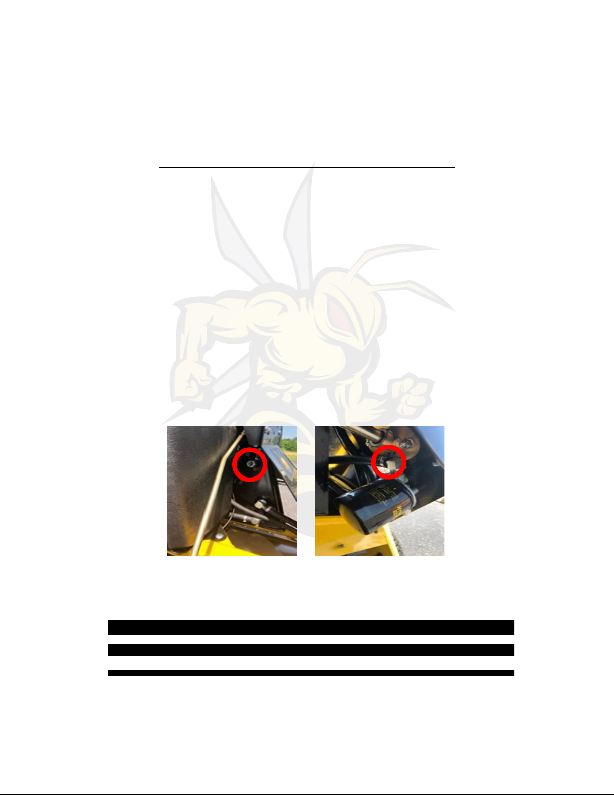
2. Release Parking brake as shown in gure 10 . Tire damage can
occur if parking brake is not released.
3. Push both steering controls forward, to move the unit forward.
The more pressure applied, the greater the speed.
4. Pulling back on both steering controls will put the unit in reverse.
5. Reduce the speed of the le or right steering control while moving
forward to turn le or right.
6. Always set parking brake before stepping o or turning o the
unit.
Figure 10
Usage
1. Lower aeraon nes into the ground by holding the foot pedal
down (gure 11) or switching the ne posion switch to down.
2. Lock the nes in the up posion by switching to transport.
3. Tines can remain in the ground when making wide gentle turns.
For sharper turns and 180’s the nes must be lied prior to
turning this will prevent turf damage.
4. Always li nes prior to transporng and crossing over concrete,
tree roots, and other hard surfaces.

11
Always consider what might be below the turf prior to aerang.
Does the property have unground ulies, invisible dog fence, low
voltage lighng, irrigaon., etc.?
Calling 811 or a private locate services is strongly recommended and
maybe the law. Take appropriate acons to prevent damages
Figure 11

www.SngerEquipment.com
2140 Spencer Court LaGrange, KY 40031
(502) 536-0716
Other manuals for Quad-Aer
1
Table of contents
Popular Offroad Vehicle manuals by other brands

Polaris
Polaris Scrambler 9921298 owner's manual

Yamaha
Yamaha BIG BEAR YFM400FPR owner's manual

Polaris
Polaris Hawkeye 922362 owner's manual

Hammerhead
Hammerhead Rave 150 HH150 Operator's manual

Polaris
Polaris 9922462 Owner's manual for maintenance and safety

Ski-Doo
Ski-Doo EVEREST 444 L/C 1977 Operator's manual