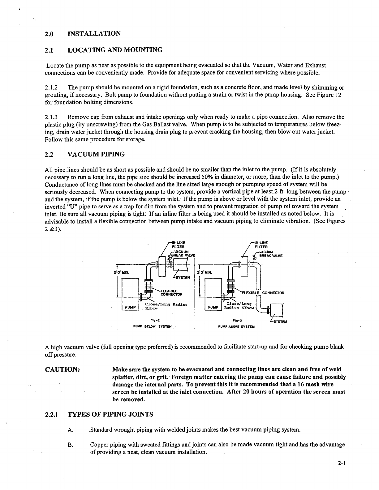
Stokes Microvac 412H-11 User manual

INSTRUCTIONS
PART
I
Section
Page
1.
DESCRIPTION
1.1
General
1-1
1.2 Gas Ballast
1-1
1.3
Water System 1-2
1.4 Electrical System
1-2
1.5
Lubricants
1-2
1.6
Guards
1-2
1.7
Vacuum Break & Gage Ports \-2
2.
INSTALLATION
2.1 Locating and Mounting
2-1
2.2 Vacuum Piping
2-1
2.3 Exhaust Piping 2-2
2.4 Electrical Connections 2-2
2.5 Cooling 2-3
2.6 Lubrication
of
Pump 2-4
3.
OPERATION
3.1
Pre-Start Check
3-1
3.2 Pump Start
3-1
3.3 Checking Oil Level 3-1
3.4 Operation
of
Gas Ballast 3-2
3.5 Pump Stop 3-3
3.6 Operating Notes 3-3
4.
CHECKING
4.1
Poor Vacuum 4-1
4.2 Localizing Leakage 4-1
4.3 Repairing Small Leaks 4-1
4.4 Pump Activity Record 4-1
5.
MAINTENANCE
5.1
Initial Servicing 5-1
5.2 Pump Disassembly 5-3
5.3 Troubleshooting Guide 5-11

6.
MAJOR ATTENTION ITEMS BULLETIN AND MAINTENANCE CHECK LIST
7. PARTS LIST
8.
STOKES SUPPLEMENTARY DATA
Parts Ordering Infonnation
Recommended Replacement Parts Kit
Stokes Microvac 2-Year Warranty
Pumping Hazardous Gases Sheet
Pumping Fluids, Lubricants'and Grease Bulletin
ILLUSTRATIONS
Figure
I.
Pump Cross Section View
2.
Vacuum Piping (Pump Below System)
3.
Vacuum Piping (Pump Above System)
4.
Exhaust Piping
5.
Wiring Diagram
6.
Gas Ballast Check Valve
7. Standard Vacuum System Piping
8.
Exhaust Valve Assembly
9.
Taper Lock Bushing, Installation
10.
Rotary Oil Seal
II. Exploded View
of
Pump
12.
Specifications
Page
1-1
2-1
.
2-1
2-2
2-3
3-2
4-1
5-2
5-3
5-5

1.0
DESCRIPTION
1.1
GENERAL
(Principle
of
Operation)
..
The Stokes Model
412..:11
Microvac Pump
is
a self-contained, rotary, oil sealed piston type unit. The piston
is
driven
by an eccentric mounted on the drive shaft and the piston slided
is
guided by two floating hinge bars that are free to
oscillate in the pump housing. Facing the drive
end:the
piston assembly rotates clockwise. Air enters the pump through
the intake and then through the piston slide until the piston completes its stroke. At this point all air previously en-
trapped
is
in front
of
the piston as it begins another stroke. As the piston continues to rotate, the air in front
of
it
is
compressed and discharged through the exhaust valve and fmally out the exhaust outlet. As the piston nears the top
center position the intake port
is
closed, separating the system from the pump (See Figure
I).
The exhaust valves are
of
the corrosion-resistant, heavy duty, poppet type. When the pump
is
in operation, lubrication
of
the internal parts
is
completely automatic. Oil
is
forced by atmospheric pressure from the reservoir through the oil lines to the shaft
bearings. The oil
is
then fed into the pump to provide the necessary piston-to-cylinder oil seal. Finally, the oil
is
forced out through the exhaust valve with the air and returns
to
the reservoir. A solenoid valve automatically prevents
oil from flooding the pump
in
the event
of
a power failure, or when the pump
is
shutdown without vacuum being
broken.
EXHAUST
I-i.+---
OIL
SEPARATOR
OIL
POPPET
VALVE
PISTON
Ell
SLICE
HINGE
BARS
eCCENTRIC
FiQ I
1.2
GAS
BALLAST
The pump
is
provided with a manually operated gas ballast valve to overcome the adverse affect on vacuum resulting
from oil contamination. Contamination occurs when water vapor or other gaseous components enter the pump and
condense within the pump mixing with the oil
as
emulsified droplets.
The
condensate will mix with the oil and "flash"
. into vapor again as the oil circulates into high vacuum in the pump cylinder limiting the vacuum to the Vapor pressure
of
the condensed water. Gas Ballast
is
a controlled bleed
of
air from the atmosphere. This air caries the water vapor
through the compression cycle without it condensing to liquid and mixing with oil. Thus, the water vapors are ex-
hausted without contaminating the pump oil. Other contaminates are also removed by ballasting except those that
dissolve in the oil.
NOTE:
Never use gas ballast when pumping gases
or
gas mixtures that
are
explosive
or
flammable.
1-1

1.3
WATER
SYSTEM
A supply
of
cooling water at
85°
F. and 2 G.P.M. maximum
is
needed at the water inlet for efficient performance. See
Section 2.5 for additional information.
1.4
ELECTRICAL
SYSTEM
The main power supply
is
230/460V., 60 Cy., 3 Ph. and should be wired through a suitable fused motor starter. Power
for the oil solenoid
is
taken from any two
of
the motor leads. Check both motor and solenoid nameplates to insure
proper voltage.
1.5
LUBRICANTS
Refer to Section 2 for recommended high vacuum grease and pumping fluids.
1.6
GUARDS
The standard pump is with a totally enclosed belt guard to cover the motor pulley, pump pulley and belts.
1.7
VACUUM
BREAK & GAGE
PORTS
The pump is provided with a
112"
FPT Vacuum Break & a
1/4"
FPT Gage Port, as shown in Fig.
II.
IMPORTANT:
When using Gage
Port,
provided a
90°
elbow
and
at
least
12"
of
vertical
pipe
to
the
gage sensor.
1-2

2.0 INSTALLATION
2.1
LOCATING
AND MOUNTING
Locate the
pump
as near as possible to the equipment being evacuated so that the Vacuum, Water and Exhaust
connections can be conveniently made. Provide for adequate space for convenient servicing where possible.
2.1.2 The
pump
should be mounted on a rigid foundation, such as a concrete floor, and made level by shimming or
grouting,
if
necessary. Bolt pump to foundation without putting a strain
or
twist in the
pump
housing. See Figure
12
for foundation bolting dimensions.
2.1.3 Remove cap from exhaust and intake openings only when ready to make a pipe connection. Also remove the
plastic plug (by unscrewing) from the Gas Ballast valve. When pump is to be subjected to temperatures below freez-
ing, drain water
jacket
through the housing drain plug to prevent cracking the housing, then
blowout
waterjacket.
Follow this same procedure for storage.
2.2 VACUUM PIPING
All pipe
lines
should be as short as possible and should be no smaller than the inlet
to
the pump.
(If
it
is
absolutely
necessary
to
run a long line, the pipe size should
be
increased 50% in diameter, or more, than the inlet to the pump.)
Conductance
of
long lines must be checked and the line sized large enough
or
pumping speed
of
system will
be
seriously decreased. When connecting pump to the system, provide a vertical pipe at least.2 ft. long between the
pump'
and the system,
if
the pump is below the system
inlet."·
If
the pump is above or level with the system inlet, provide an
inverted
"U"
pipe to serve as a trap for dirt from the system and to prevent migration
of
pump
oil toward the system
inlet. Be sure all vacuum piping is
tight
If
an inline filter
is
being used it should be installed as noted below. It is
advisable
to
install a flexible connection between pump intake and vacuum piping to eliminate vibration. (See Figures
2 &3).
r-----
i.O·MIN.
PUMP.
Close/Lonq
Radius
Elbow
""'2
PUIIP BELOW
SYSTEII
••
..........FLEXIBLE
CONNECTOR
PUM-P--H+R-;~!~L-..~:/~~~:;'
.~
._11
II
F1
v-3
~TEM
PUMP ABOVE SYSTEM
A high vacuum valve (full opening type preferred) is recommended to facilitate start-up and for checking
pump
blank
off
pressure.
CAUTION:
Make
sure
the
system
to
be
evacuated
and
connecting
lines
are
clean
and
free
of
weld
splatter,
dirt,
or
grit.'
Foreign
matter'
entering
the
pump
can
cause
failure
and
possibly
damage
the
internal
parts.
To
prevent
this
it
is
recommended
that
a 16
mesh
wire
screen
be installed
at
the
inlet connection.
After
20
hours
of
operation
the
screen
must
be removed.
2.2.1
TYPES
OF
PIPING
JOINTS
A.
Standard wrought piping with welded joints makes the best vacuum piping system.
B.
Copper piping with sweated fittings andjoints can also be
made
vacuum tight and has
the
advantage
of
providing a neat, clean vacuum installation.
2-1

C.
Standard threaded piping, however,
is
satisfactory and more readily installed. The piping should be
carefully hammered to loosen any scales or chips.
Blowout
the resultant with compressedair prior
to installation. All male threaded joints should
be
carefully doped, screwed up tight and NEVER
"backed-off'
to
make parts align -this
is
apt to cause a leak. Paint thejoints while the system is
under vacuum until the paint is no longer drawn in, G.E.
12Ol-B,
Glyptal or equivalent is
recommended for painting all connections.
2.2.2
LOCATION
OF
GAGE
PORT
A vacuum gage connection
is
located at the upper left hand side
of
intake side
of
pump. (See Figure
12).
The pipe plug
found at this location should be replaced with a small vacuum ball valve to which the gage can be connected. When a
Stokes McLeod Gage
is
used a synthetic, thick wall, smooth bore tubing, such as Tygon, makes a very satisfactory
flexible connection.
2.3 EXHAUST PIPING
2.3.1
It
is
recommended that the exhaust be piped horizontally as short distance and tied into a vertical exhaust pipe.
The vertical exhaust pipe must
be
at least I
ft.
long and the bottom end
of
the vertical exhaust pipe terminated with a
plug or a drain cock to allow removal
of
moisture and contaminated oil before it can accumulate sufficiently to drain
back into pump oil reservoir. See Figure 4.
£XHAUST
PIPING
Figur~
4
2.3.2 The exhaust pipe should be no smaller than the exhaust outlet and
as
short as possible. Run
the
pipe outside
the building where the pump exhaust vapors will not be objectionable
..
Point the outside end
of
the exhaust pipe
downward to prevent the entrance
of
rain water.
2.3.3 Closed circuit Oil Mist Separators are available from Stokes which can eliminate oil fog
in
the majority
of
applications. The separator will not remove noxious or toxic gases and
n;lust
be run outside the bUilding. For operating·
continually under conditions
of
higher pressure an electro-static precipitator
is
recommended. Contact Stokes for.
specifics.
CAUTION: NEVER
PLACE
A VALVE
IN
THE
EXHAUST LINE.
IF
A VALVE
MUST BE INSTALLED
IN
THE
LINE, A
RELIEF
VALVE MUST ALSO
BE INSERTED IN
THE
LINE
BETWEEN
THE
RESERVOIR
AND
THE
VALVE.
THE
RELIEF
VALVE SHOULD
BE
EQUAL
IN
SIZE
TO
THE
LINE, AND
SET
TO
OPEN
AT
2 PSIG.
2.4
ELECTRICAL
CONNECTIONS
(See
Figure
5)
CAUTION: BE SURE
PUMP
IS
PROPERLY
LUBRICATED
BEFORE
STARTING.
2.4.1· Install a motor starter with safety device within easy reach
of
the operator.
2.4.2 Connect the solenoid valve as in Figure
5.
2.4.3 Connect motor so that pump shaft rotates clockwise when viewed from driven end. See
3.1
for Pre-Start
Check.
2-2

NOTE:
MAKE
SURE
THE
PROPER
VOLTAGE, STARTERS AND OVERLOADS
ARE
SUPPLIED
TO
THE
MOTOR.
MAKE
SURE THAT
THE
SOLENOID
COIL
LEADS
ARE
CONNECTED
FOR
PROPER
VOLTAGE.
BOTH
MAY
FAIL
TO
OPERATE
IF
VOLTAGE
IS LESS THAN
90%
OF
RATED.
230/'I6O/~~0
V.,60
CY.,
3
PH.
LINE
vOLTAGE
230/460/5SDV.,
50/60
CY.,3Ft!.
LINE
VOLTAGE
LI
LI
L2
L3
1
1I
230/460/550
V.,
SO/60
cv.,
I
PH.
or
115
II,
SO/60
CY.,
I
PH.
L~'
CON~~\
VOLTAG:
L2
STOP M
2 3
O<JAL
VOLTAGE
COIL
CONNECTiONS
WI·TH
115
11
.,50/60
CY.,IPH.
. CONTIIOL
VOLTAGE
L2 1
230V.
460
V.
WIRING
OIAGRAM
Fi(Jllr~
5
Blk
Red
2.5
COOLING
2.5.1 This pump is water cooled and must be connected to a water supply.
2.5.2 The
112"
water inlet connection
is
located in the pump housing on the drive side near the bottom.
2.5.3 ·Insert a valve in the water inlet line and regulate the water flow so that the temperature
of
the oil in the
reservoir
is
between 140 Deg. and 160 Deg.
F.
Oil temperature kits are available that automatically control the water
flow to maintain the proper oil temperature (Consult factory).
Ifpump
is
outside and subjected to freezing tempera-
tures, water tank and circulating pump should be installed with anti-freeze in the water.
2-3

CAUTION:
DO
NOT
START PUMP
WHEN
OIL
TEMPERATURE IS
BELOW
55°
F.
2.5.4
The
V2" water outlet
is
located in the pump housing on the opposite side
of
the water inlet.
2.5.5 The water outlet SHOULD be connected to an open drain to permit the operator to check the flow and
temperature
of
the outlet water periodically. There SHOULD NOT be a valve or back pressure in this line. In some
cases, coolingwater must be discharged to a pressure drain. In such cases, discharge pressure must
not
exceed 50
P.S.I.G. and no block valve should be placed
in
discharge line unless a 50# reliefvalve is provided
to
protect pump
from high inlet pressure.
NOTE:
IF
CONDENSABLES ARE PRESENT IN GAS BEING PUMPED AND GAS
BALLAST IS USED
THROTTLE
THE
COOLING
WATER
TO
RAISE
OPERATING
TEMPERATURE
TO
THE
LEVEL
NEEDED
FOR
GAS BALLAST (SEE SECT. 3).
2.6 LUBRICATION
OF
PUMP
The successful operation
of
this pump depends largely
on
the type
of
oil used. An initial charge
of
ojl
is
included with
each pump. This standard oil
is
V-Lube (Label F) which
is
recommended for general operating conditions in a
relatively clean environment. The oil
is
a multigrade petroleum oil, fortified for·oxidation protection, containing
detergent dispersants, with excellent flow characteristics at low temperature.
It
has a viscosity
of
430 SSU at
100
Deg.
F., and 82 SSU at 2lO Deg. F., with a vapor pressure
of
0.0001
mm Hg. at
145
Deg. F.
If
the pump is to
be
operated at vacuum levels that cause the oil temperature to exceed 160 Deg. F. for extended
. periods
of
time, a heavier grade oil should be used, Stokes V-lube (Label G)
is
available for oil temperatures up to 200
Deg.F
.
. Special operating conditions may require the use
of
Special oils. We have listed the·most used special lubricants on the
back page
of
the Bulletin enclosed, Greasing and Pumping Fluids for Vacuum Components. Consult Stokes for
specific recommendations when other than regular petroleum oils are being used.
2.6.1
INITIAL
FILL
The microvac pump
is
shipped with
ail
Initial charge
of
oil (12 gallons)
inthe
reservoir.
Bt;:fore
connecting the suction
manifold slowly rotate the pump thru two revolutions. This will distribute the oil throughout the pump interior.
NOTE: STARTING
THE
MICROV
AC PUMP
WHEN
OIL
TEMPERATURE
IS
BELOW
55 .
DEG. F., CAN RESULT IN EXCESSIVE
WEAR
AND
GALLING
DAMAGE
TO
THE
MOVING PARTS.
'When changing oil, refer to SectionS, page
5~1
of
manual, Service and Maintenance.
2-4

3.0
OPERATION
3.1
PRE-START
CHECK
NOTE:
REMOVE
BELT
GUARD
COVER.
TURN
PUMP
OVER
BY
HAND
AT
LEAST
TWO
REVOLUTIONS.
3.1.1
A.
B.
NOTE:
Jog the motor momentarily while observing pump rotation.
If
the pump does not rotate in a
clockwise direction, interchange any two
of
the three-phase leads.
Make sure the oil solenoid valve operates properly by checking the oil flow indicator. The
ball
in
the Oil Flow Indicator bowl should rise after system pressure is below 600
mm
Hg.
(6" Hg. Suction).
IF
INDICATOR
BALL
DOES
NOT
RISE,
STOP
PUMP
IMMEDIATELY.
(1)
CHECK
OPERATION
OF
SOLENOID. (2)
CHECK
OIL
LINES
FOR
BLOCKAGE
3.1.2
DRIVE
BELT
TENSION
A.
B.
NOTE:
At approximately the center
of
the span, between drive and driven pulleys, apply 5 to 7
pounds pressure on the belt.
Iftension
is
correct, the resulting deflection should
be
112".
Adjust,
if
necessary,
by
raising
or
lowering the location nuts on the motor support eyebolt
(39). Tighten these nuts securely after adjustments.
MAINTENANCE
OF
PROPER
BELT
TENSION
IS
IMPORTANT.
TOO
TIGHT
ANY
ADJUSTMENT IS
HARMFUL
TO
THE
SHAFT
BEARINGS.
TOO
LOOSE
AN
ADJUSTMENT
ALLOWS
THE
BELT
TO
SLIP.
3.2
PUMP
START
3.2.1
Tum
cooling water ON.
3.2.2 Depress "start" button and check solenoid valve for proper operation.
CAUTION: DO
NOT
START
PUMP
WHEN
OIL
TEMPERATURE
IS
BELOW
55°
F.
3.2.3
Be
sure the equipment being evacuated is properly cleaned and all openings closed. Open intake valve.
NOTE:
REMOVE
PLASTIC
PLUG
FROM
EXHAUST
PORT
BEFORE
OPERATING
PUMP
3.3
CHECKING
OIL
LEVEL
3.3.1 Check oil level each day.
3.3.2 The oil level should be at center
of
sight glass
or
in lower
half
while pump"is operating
at
high
vacuum.
Level will change depending on suctiori pressure. In most cases, oil
is
added
after operating the
pump
for
a short
while.
3.3.3 To
avoid
blowing oil out the fill hole, do
not
add oil
to
the pump when in operation unless
pump
is at I
torr or less without Gas Ballast.
NOTE:
When
pumping gases
that
contain
water
vapor
it
may
be necessary
to
remove
the
water
that
condenses in
the
pump
reservoir
sump.
This
can
be
done
by
opening
the
oil
drain
valve
and
draining
out
water,
and
closing valve when oil
starts
to flow.
The
interval
for
this
must
be
determined
for each specific
operation
and
depends on
the
amount
of
water
vapor
and
oil
temperature.
Operating
the
pump
with
the
oil
temperature
in
the
160
Deg. F.,
temperature
range
will
tend
to
minimize formation
of
water,
but
will
not
eliminate it.
3-1

3.4
OPERA
TION
OF
GAS BALLAST
3.4.1
Open the Gas Ballast valve fully for maximum efficiency. For a lesser degree
of
ballasting,
tum
valve toward
close position. Full gas ballast will cause pump temperature to rise but this
is
nonnal. For maximum effect
of
gas
ballast, pump should
be
run approximately at
160
Deg.
F.
Operating temperature can be raised by throttling cooling
water. Oil Temperature Control Kits are available, consult factory.
NOTE: Be sure to remove the plastic plug in the Gas Ballast
air
intake lines. This plug
is
used
for
shipping
and
storage purposes ONLY
3.4.2
If
pumping water vapor in excessive quantities and the oil has become contaminated, it can be purified by
running the pump with Gas Ballast valve full open while the pump
is
shut-offfrom the system. When excessive
contaminants are present, indicated
by
high oil level, or thinning, formation
of
varnish, etc., the oil should be replaced.
NOTE: In dirty applications
where
condensable contaminants (asphalt, pitch, epoxies, etc.)
other
than
water
vapor
are
present,
the
pump
should be operated in the
range
of
160
Deg. F.
CAUTION: Gas Ballast should never be used
ifvapors
being pumped
are
explosive, e.g.
Methane
Gas, Hydrogen,
and
certain
solvent vapors. When gases
of
an explosive
nature
are
being
handled. the safest
procedure
is
to remove the gas ballast valve entirely
and
plug
or
cap
the
pipe to which the gas ballast valve
is
attached.
Opening the gas ballast slightly will quiet valve noise when pump
is
blanked-off, but will prevent reaching the lowest
final pressure.
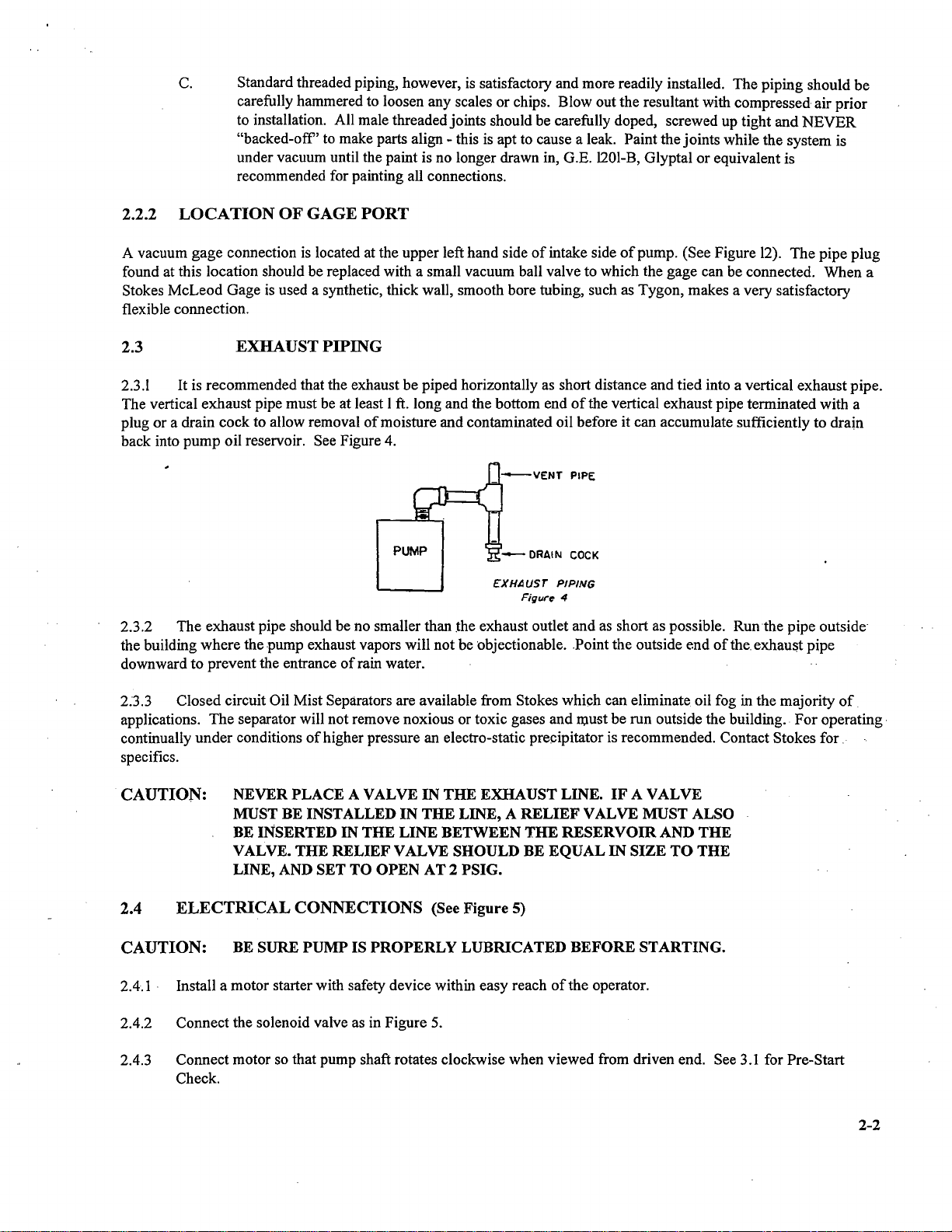
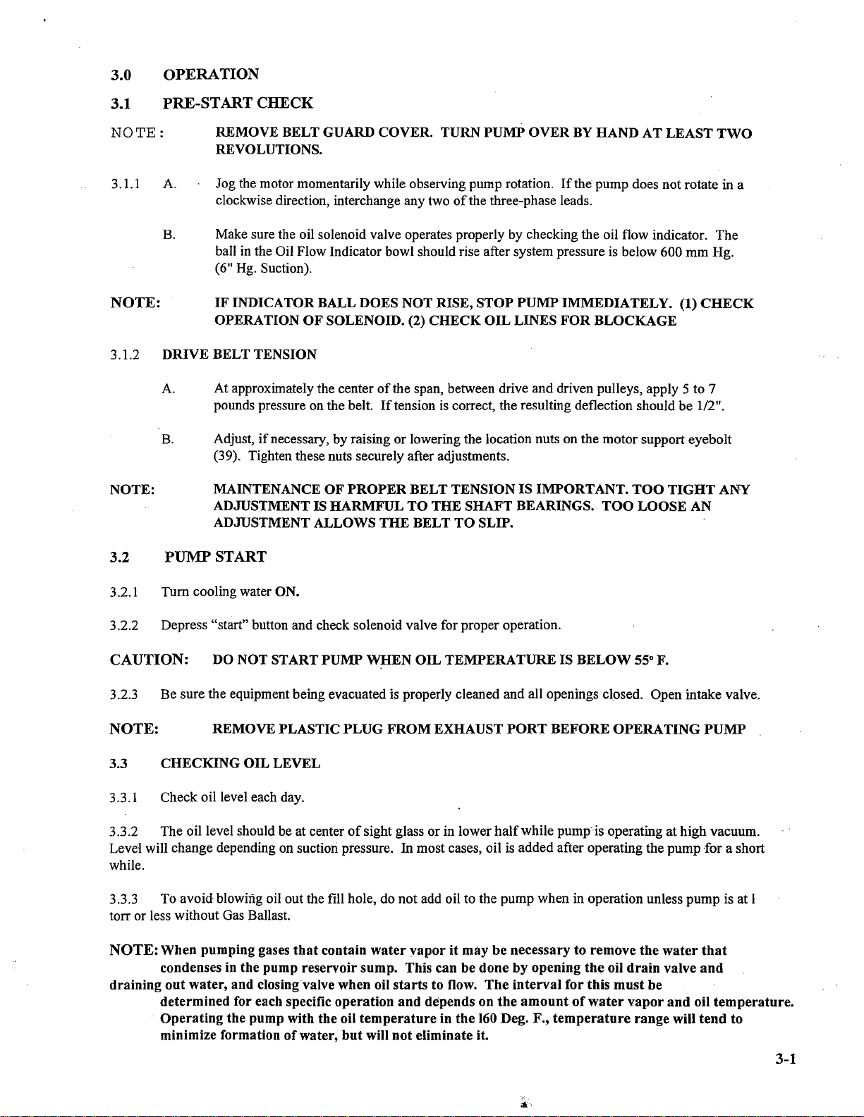
3.4.3 The check valve used for Gas Ballast should be inspected at least every six months for
we.ar
or a broken spring
when operating on an (8) hour a day basis; every 3 months for (24) hour a day operation.
TEFLON
BACK·
UP
lUNG \ &
STATIC
"0"
RING
\ \
~
t"\~
>
~\J'-J,~,/
L)~
"-""'.'C"O"
.,,'
~
\..
..
,,"'
SCREEN
(nor
r.".,vall/e
1
GAS
BALLAsr
CHECK
VALVE
Flgur.6
3.4.4 The gas ballast valve should be closed when the pump
is
stopped..
If
the valve
is
open, gas will be sucked into
the pump through the valve·and the vacuum manifold will be pressurized with atmospheric air. This air
goir).g
through
the pump will carry the oil in the pump cylinder system. A solenoid valve attached to the gas ballast piping and
connected across the motor can be used to tum the gas ballast automatically on pump shutdown. Contact local Stokes.
representative for additional infonnation.
3.4.5 When a pressurized gas is used to ballast the pump, the pressure must
be
reduced to 2 psi maximum. The used
of
higher pressures may damage the pump.
3.4.6 When pumping an explosive gas, (Le. hydrogen, silane, methane) or corrosive gas, (cl,
f,
ccl4, etc.) the pump
must be ballasted with an inert gas (nitrogen, argon). The used
of
air for ballasting under the above conditions can
..
result
in
an explosion or excessive corrosion inside the pump.
3-2

3.5
PUMP
STOP
3.5.1 Close intake valve to system.
3.5.2 Stop
the
motor and break vacuum unless system dictates otherwise
..
NOTE:
The
solenoid valve closes automatically when the pump
is
stopped
or
in case
of
power
failure,
thus preventing pump
and
vacuum system from being flooded with oil.
3.6
OPERATING
NOTES
3.6.1
If
large amounts
of
air pass through the pump, it may become warm and under severe conditions
may
become
hot. This does
not
indicate trouble. The pump is designated for high vacuum work and should not be operated at
pressures above
600
mm
Hg. for more than
15
minutes or at intermediate vacuums for periods which cause oil tempera-
ture to exceed
200
Deg.
F.
For optimum pump operation the oil temperature
of
the oil in the reservoir should be
between
140
Deg. F. and
160
Deg.
F.
with the pump operating on the system
or
process. Oil temperature can be
-measured by inserting a thermometer
in
the fill hole
or
by contact pyrometer on oil line near the solenoid.
If
the
pump
is
to be operated with oil temperature
in
excess
of
160 Deg. F. the use
of
a heavier viscosity oil is recommended. (See
Section 2.6.)
3.6.2 When starting the pump
or
when handling large amounts
of
air, oil vapor in the form
of
smoke will
issue
from
the exhaust.
Again
this is no indication
of
trouble,
as
the volume
of
smoke will decrease as the vacuum in
the
system
improves.
NOTE:
Stokes closed type oil mist
separator
is
available to alleviate exhaust oil smog
..
3.6.3
If
the
pump
has been shut down for an extended period, always turn over at leasttwo (2) revolutions by hand
before starting to insure free movement
of
parts.
3.6.4 Low .oil temperature can.cause overloading when starting the pump and possibly prevent the pump from
sealing. Microvac pumps should not be started.when the oil temperature.is below 55 Deg. F.*Optimum operating
oil..
. temperature after starting is between
140
Deg. F. to
160
Deg. F. Opening the Gas Ballast valve will help warm-up the
oil.
A Water Miser is recommended to automatically control
the
oil temperature.
*THIS APPLIES ONLY
IF
STOKES V-LUBE
"F"
IS USED. CONSULT
FACTORY
IF
OTHER
OILS
ARE
USED.
3-3

4.0
CHECKING
4.1
POOR
VACUUM
No pump will give good results on a poor vacuum system.
If
the vacuum in the system
is
unsatisfactory, the usual
cause is leakage. To check for this condition, a methodical approach will usually resolve the.problem in the least
amount
of
time.
4.2
LOCALIZING
LEAKAGE
A leak rate will help localize a vacuum leak. Such a test
is
easily made by successively isolating and evacuating each
section
of
the system. The in-leakage rate
of
the isolated section
is
then noted.
4.2.1
A vacuum leak detector will speed up the process
of
the locating leaks.
VACUUM
CHAMBER
-po
iROUGHING
VAL~~
-----:-------1"..ft
....
t-:-----------"
---------t,.'"
'.1------------, \
..
-
___
ALTERNATE
LDCATIONS
I :
---
FOR
CHAMBER
GAGE
PORT
I t
VAPOR
PUMP
I
1-
ROUGHING
LINE
I .
I I
I
. I I
I I
\
F SEPARATE
HOLD
: I
PUMP
IS
NEEDED
I .
CONNECT
HERE/tfl
FORELINE VALVE
I t (Required
if
separate
I I roughin9 line is used I
--~----t'-.J:J""!I"-....I......(
-GAGE
PORT
-AIR
INLET
VALVE
PORT
MECH.
FOREPUMP.
STANOARO VACUUM SYSTeM
PIPING
Figur~
7
4.3
REPAIRING
SMALL
LEAKS
To repair small leaks orto close pores, use Sealing Compound, Stokes Part No. 4-927. When replacing plug type
valves
(if
used) use Locktite Pipe Sealer No.
714-1
to help seal them. Gate, Ball or Butterfly type high vacuum
valves.
are preferred for high vacuum service.
NOTE: Use
of
Teflon
Tape
for sealing
is
not
recommended.
Material
is often
drawn
into system,
causing
premature
wear
and
damage
to moving
parts.
4.4
PUMP
ACTIVITY RECORD
A record
of
oil changes, work done on pump, and changes or additions to the system will
be
of
value in checking for
leaks or poor vacuum.
NOTE:A
sample
mechanical vacuum
pump
preventive
maintenance
check list along with a
summary
of
major
attention items
is
enclosed for
your
review.
4-1

CAUTION
WHEN
REASSEMBLING
PUMP
BE
CERTAIN
ALL
MOVING
PARTS
ARE
CLEAN
AND
LUBRICATED.
BEFORE
STARTING
PUMP
POUR
10%
OF
THE
REQUIRED
AMOUNT
OF
OIL
INTO
INLET
WHILE
SLOWLY
ROTATING
PUMP
THRU
TWO
(2)
REVOLUTIONS.
POUR
REMAINDER
OF
-
OIL
INTO
THE
RESERVOIR.
NOTE:
THE
JOINT
BETWEEN
THE
RESERVOIR
AND
HOUSING
MAY
BE
SEALED
BY
THE
FACTORY
WITH
A
GASKET
OR
LOCTITE
GASKET
ELIMINATOR.
CONTACT
FACTORY
IF
NEED
ARISES
TO
REMOVE
RESERVOIR
THAT
HAS
BEEN
SEALED
WITH
GASKET
ELIMINATOR.
~
..

5.0 MAINTENANCE
The Stokes 412-11 Microvac Pump
is
of
rugged construction and designed for trouble free performance. However, to
insure effiCient performance and minimum wear the following procedures are recommended:
5.1
INITIAL
SERVICING
5.1.1
First
Three
Weeks
of
Operation
A.
Check oil level daily and also its condition. (See Paragraph
5.1.3).
Maintain oil level at
center
of
sight glass with pump
in
operation.
B.
Check belt tension weekly (See Paragraph 3.1.2).
C.
Check the foundation bolts weekly.
5.1.2
After
First
Three
Weeks
of
Operation
A.
Check oil level daily.
B.
Check "V" belts, tension and wear every 3 months
C.
Tighten all flange side cover bolts and foundation bolts at regular intervals.
5.1.3
Changing
Oil and Cleaning
Pump
Reservoir (See Figure 11)
Change oil every 300 hours
of
operation and clean reservoir every 600 to 900 hours
of
operation
..
For dirty applica-
tions decrease bil change intervals. Also
if
the oil becomes contaminated (indicated bydarkening in color and/or poor
pump performance) it should be drained. Drain the reservoir and exhaust valve chamber. Wipe the reservoir clean
before filling with new oil. Milky appearance
of
oil indicates water contamination. Use Gas Ballast to clear oil, or
change oil. Also most water can be removed
by
draining water from pump before starting pump.
To
change oil and clean reservoir proceed
as
follows:
A.
With pump running, close intake valve to system and open vacuum break valve-to.pump or
open intake valve and admit atmosphere to the system so that atmospheric pressure forces
oil
from the pump interior up into the reservoir. Run pump for approximately 30 seconds, then
tum pump OFF.
B.
Drain oil by opening drain cock (51).
C.
After oil has been drained remove oil reservoir cover (32) being careful·not to damage gasket
(31).
D.
Thoroughly wipe out oil reservoir,
DO
NOT
flush the reservoir with Kerosene, Gasoline
or
any other solventthat may,
if
not completely removed, contaminate the pump oil. Use only
clean, dry, lint-free towels.
E.
Replace gasket (31) and cover (32) and tighten securely.
5.1.4 Cleaning
Exhaust
Valve Assemblies
and
Chamber
When the oil
is
badly contaminated the exhaust valves and chamber should be cleaned. Referring to Figure
11
proceed
as
follows:
A.
Repeat Steps 5.1.3, A to
D.
B.
.Remove oil baffle (28) and valve cover plate gasket (27).
5-1

NOTE:
C.
Drain
the oil from the valve
chamber
by
removing the plug on the
dead
end
side
of
the
pump
housing. (See Figure
12)
D.
E.
F.
G.
'----26A
_--::;""::::;.J
-----268
'-----260
VALVE
ASSEMBLY
Figurtt8
Remove
valve assembly (26), by removing the six cap screws,
and
valve gasket (25).
To
disassemble
valve
assembly
(26),
remove
center
cap
screw,
lift
off
valve
cap
(26
A),
remove
spring
(26
B)
and
valve
disc
(26
C).
Clean and inspect valve parts, and
wipe
out
valve
chamber
with clean, dry lint-free towels.
Reassemble valve assemblies
by
reversing the disassembly steps described above.
It
is
. advisable to use a
new
valve gasket (31) when reinstalling valve assemblies.
Replace valve
chamber
plug.
5.1.5
Care
of
Exhaust
Valves
The
valves are
the
poppet
type and corrosion resistant construction.
These
valves
operate
many
millions
of
cycles
per·
year
in
nonnal
operation and should be inspected
at
least once every six months
even
though
the
pump
is
operating
satisfactorily,
and
more
frequently where. duty
on
pump
is severe
..
The
valve should
be
disassembled
and
cleaned
ill
accordance
with
Section 5.1.4.
At
the
time
ofthe
inspection, it is advisable
to
replace the entire set
of
springs
and
valve
discs. This
procedure
will increase the reliability
of
the pump, avoiding
the
possibility
of
additional
spring
failure.
5.1.6
Solenoid
Valve
Check
Solenoid Valve, which prevents oil from flooding
the
pump
in
case
of
a
power
failure,
at
regular
intervals;
See
page
3-1
para. 3.1.B.
In
the
event
the solenoid valve stays
closed,after
the
pump
is started,.the
oil
cannot
circulate.
This
is indicated
by
poor
perfonnance
and
if
the conditjon is allowed
to
continue
for
any
length
of
time, the
pump
may
suffer
damage.·.
The
pump
work-in
period
.establishes the
nonnal
preventive
maintenance
checks
according
to the type
of
system (clean
or
dirty) being
pumped
down
and the
continuous
pumping
time
(light
of
heavy).
In a clean
and
light
pumping
situation,
the
exhaust valve springs
and
discs should
be
replaced
every six
months.
At
this time the reservoir should.
be
checked
for
sludge accumulation and foreign particles.
Use
a
magnet
to
detect
presence
of
foreign metal particles.
The
presence of.sludge and/or
foreign
particles in
the
reservoir indicates
the
same
condition exists in
the
oil solenoid valve. This condition will cause
the
solenoid
valve
to
stick
in
the
open
or
closed
position. Disassemble
and
clean the solenoid
valve.·
Replace
any
worn
parts.
If
the
pump
is
used
in
a dirty
and
heavy
pumping
situation, the preventive maintenance checks should be
perfonned
sooner.
It
is strongly suggested
that
a spare oil solenoid valve be on
hand
at
all
times
to
keep
pump
downtime
at
an absolute
minimum.
When operating with
pump
oils other than
that
supplied, special
gasket
material
may
be
needed
in
the
solenoid
valve -
consult factory.
The
visual flow indicator
on
latest
pumps
makes
this
check
simple
by
indicating flow
when
pressure is
below 600
mm
Hg. (6" Hg. Suction) 5-2

5.2
PUMP
DISASSEMBLY
5.2.1
Removal
of
Shaft
Seal-
Flywheel
End
(See Figures
10&
11)
The
shaft
seal
used
on
this
pump
are the mechanical face type. Since their efficiency depends
on
the
highly
fmished
. surfaces, it is extremely
importantto
handle them with care.
They
should require little
or
no
attention,
but
if
excessive
leakage
occurs,
they
can be removed for service as follows:
NOTE:
NOTE:·
A.
To
remove the pUlley.
B.
c.
D.
E.
F.
1)
Unclasp (4) hinge locks
on
belt guard.
2) Lower the adjusting
nut
on
motor
support
eye
bolt (39)
to
relieve all tensions
on
the drive belts.
3) Remove the belts.
4) Insert screw in hole
that
is threaded through
bushing
side (See
Figure
9).
One
screW in each hub is left
over
and
not
used in
loosening
operation.
5) Tighten screws alternately until bushing is loosened in hub.
If
bushing
does
not
loosen immediately, tap
on
hub.
\
OA
INSTALLATION
~
'~---1
. I
1--
~
rAPER-LOCK
BUSHING
INSrALLAriON
.";(lu~
9
To
assure
proper
seal assembly,
check
exploded
view, Figure
II,
for
proper
orientation...
Remove Key (14) from the shaft
and
remove
any
burrs
around
the
keyway.
Remove (4) 5116-18 Screws
and
Plastic washers
which
hold
belt
guard
back
plate in place.
Disconnect the oil line from
the
hub
of
side
cover
(12).
Take out screws
that
secure
end
cap
(5) to the side
cover
and
remove
the
end
cap
and
"0"
ring (6).
Inspect the face
of
seal
port
(7e) retained
by
the
end
cap.
5-3

NOTE:
The
inner seal ring (7e) may be removed from the seal
outer
seal ring (7b) for inspection. (7b)
is
pressed in the end cap(s). Depress
and
rotate the seal ring (7e) releasing
the
bayonet
lock,
and
remove from
outer
ring (7b). Inspect
the
"0"
ring (7c)
and
spring
(7d) for possible
damage. Removal
of
the
outer
ring (7b)
is
not recommended unless replacing
the
entire
oil
seal.
G.
Remove the seal matting ring (7g) with a slight back and forth rocking motion. Earlier model
pumps have a socket head cap screw
in
the ring,
if
so, loosen screw halfway then remove
mating ring (7g).
H.
Whenever the pump
is
disassembled and the rotary seal parts 7e & 7g are separated,
it
is
advisable that these parts be lapped to a 2-lightband flatness or replaced.
If
the normal ridge
on member (7e)
is
worn flat, replace this part. Always check bearing
(11)
for wear and
replace
if
necessary. Also,
if
a leaking seal
is
replaced, it
is
advisable to replace the bearing (11).
IMPORTANT: Before replacing the seal, lubricate the shaft and seal members and
"0"
ring with a thin
coat
of
vacuum grease or pump oil. Replace the sealmating ring on the shaft using a slight
back and forth motion. However, the seal mating ring should still maintain slight free
movement on the shaft.
1.
The seal
is
reassembled by reversing the disassembly procedure.
J.
Replace the Pulley.
I.
CLEANthe bushing, shaft, and bore
of
pulley.
2.
Place bushing in hub and match halfholes to make complete holes. Place the
screws loosely
in
holes that are threaded on hub side. (see Figure 9).
3. Make sure bushing is·free
in
hub and slip the assembly onto the shaft locating it in
the position desired. BE SURE.to counterweight
is
opposite the bushing keyway
. to avoid imbalance.
4.
Tighten screws alternately and evenly until all are pulled up VERY
TIGHTLY.
Use a piece
of
pipe or wrench to increase leverage. (Wrench torque
is
430 pounds
-inches).
5.·
Hammer against large end
of
bushing being careful to use a block
or
sleeve to
avoid damage to the bushing. The screws can now be turned a little more using the
specified wrench torque.
REPEAT
THIS ALTERNATE
HAMMERING
AND
SCREW
RE-TIGHTENING UNTIL
THE
SPECIFIED
WRENCH
TORQUE
NO
LONGER
TURNS
THE
SCREWS.
[)~
(\)\~
\
\(Place
toward
unlor
(\~\J~\
\ '
..
_.,
V \ c
\ B
A
HOrAI7Y
OIL
~AL
FigUl"t!
10
5-4

,"'PLY A
L,,"Y
COAY
DF
YAc;UUM
MUW.
TO
TIIII
"D"
IIIN8
ONLY
-----~"""'"~
INSTALLATIONNOTES
1.
Remove existing seal from shaft and in counter bore
of
end cap.
2. After removing seal from package, make sure the spring fits freely inside carbon seal and over
the
lip on
the spring retainer.
3. Make sure the
"0"
ring retainer (which fits between the
"0"
ring in the carbon seal and the spring).
fits freely over the pump shaft.
4. Clean the counter bore
of
the end cap. This counter bore should be free
of
oil and all foreign matter.
5.
..
Before inserting static seat, coat the back surface and approximately up
1/8"
of
the lower portion
of
the
counter bore with Loctite 620, adhesive Loctite *PrimerN to be used before applying.the Loctite 620.
6.
Clean static seat and polished surface
of
tool with a lint free cloth. Apply Primer
"N"
to back surface
of
the static seat. Gently press seat into end cap using fmger pressure only. Make sure the polished
surface is facing toward you. Take care to protect this surface since this forms the seal when in contact
with the carbon face. Gently place the polished undercut end
of
the tool* on the static seat surface.
(This surface must be flat within two light bands). Apply finn pressure, do
not
exceed 25 lbs. Hold for
two minutes to setLoctite. The
"0"
ring on the static seat will keep the Loctite from
oozing
out
and
forming on the polished surface. The Loctite forms a
vacuum
seal between the static
seat
and
end
cap.
** Tool can
be
purchased from Stokes Vacuum, Inc.,
part
No. A-427-740-l
or
made as
per
Figure
2.
7. . Slide the·spring retainer, spring, and carbon seal with
"0"
Ring and
"0"
Ring retainer
in
place as
shown, onto the pump shaft, making sure the
"0"
Ring passes over the taper
on
the shaft and the·
spring retainer rests against the threaded shoulder on the shaft. Be careful
not
to nick
or
scratch theshaft
since this will affect the seal
of
the carbon
"0"
Ring.
8.
Replace end cap with
"0"
Ring. Coat the
"0"
Ring in end cap only with vacuum grease.

NOTE:
*It
is
very important the Primer
"N"
is
used. The combination
of
620 Adhesive
and
PrimerN Gives a
bond
with a
shear
stress that permits the static seal
to
be
pressed out. Also this combination will allow the Loctite to
be
removed from
the
parts when the bond is broken. Primer
"N"
to dry 2 to 5 minutes.
Apply
adhesive 620
to
counter
bore only.
It
is recommended that the static seat be installed within
10
minutes after adhesive 620 is applied over
primer.
fjg.::1.
f~
~~U=~~=T~.
STATIC
SEAT
/L
kR
.
+.010
2.172",000
SURFACE
"A"
O'G.
NOTES-
I
6'4
R
,-
MAr'L.--f'-fOH.R.
STEEL, HEAT
TREAT
TO
RC52-S$
2-
6--
F.A.O.
EXCEPT
AS
NOTED.
3-
SURFACES
MARKED
V MUST
BE
PARAULL
WITHIN
.002.
-f-
SURFACES ·MARKED
"AN
TQ
BE
FLAT
WITHIN
TWO
LIGHT
BANds
&
FREE
OF
SCRATCHES.
F..!.g.-.L
5-6
Table of contents