Stratus TA10 Series User manual

1
www.automationdirect.com STRATUS TA10 Series Industrial Air Conditioners User Manual
2nd edition, Rev. C.
TA10 Series
User Manual

1-800-633-0405
2STRATUS TA10 Series Industrial Air Conditioners User Manual
2nd edition, Rev. C. 1-800-633-0405
Stratus TA10 Series
User Manual
Please include the Manual Number and the Manual Issue, both shown below,
when communicating with Technical Support regarding this publication.
Manual Number: STRATUS_TA10_UM_WMO_2ed_RevA
Issue: 2nd Edition Rev. A
Issue Date: 12/16
Publication History
Issue Date Description of Changes
First Edition 08/02/2010 Original
Second Edition 06/05/2014
Rev. A 12/12/2016 Unit Specifications Amps and Refrigerant
Updated, pgs 8-9
Frame Size 2 Dimensions Drawing
Updated, pg 19
Frame Size 3 Dimensions Drawing
Updated, pg 21
480V Schematic, Note Added pg 25
Manual renamed Stratus TA10 User
Manual
Logo changed from Trademark to
Registered Trademark
Rev B 07/2/2018 Unit Specifications Amps
Updated, pgs 8-9.
Rev C 04/24/2019 Unit Specifications
Updated, pg 8.

3
www.automationdirect.com STRATUS TA10 Series Industrial Air Conditioners User Manual
2nd edition, Rev. C.
3
www.automationdirect.com
Table of ConTenTs
Overview 5
Unpacking STRATUS Air Conditioning Equipment 6
What’s in the Box 6
Nameplate Information 6
Inspecting the Equipment 6
Basic Operation 7
Features 8
Unit Specifications 8
Preliminary Testing 10
Mounting the Air Conditioner 10
System Operation 11
System Faults 11
Alarm Conditions 11
Digital Temperature Controller 12
Functions and Parameters 13
Preventative Maintenance 15
Troubleshooting Guide 16
Dimensions 17
Schematics 23
Notes and Model Information 26

1-800-633-0405
4STRATUS TA10 Series Industrial Air Conditioners User Manual
2nd edition, Rev. C. 1-800-633-0405
4
~ WARNING ~
Thank you for purchasing automation equipment from Automationdirect.com™, doing business as AutomationDirect. We want your new automation equipment
to operate safely. Anyone who installs or uses this equipment should read this publication (and any other relevant publications) before installing or operating the
equipment.
To minimize the risk of potential safety problems, you should follow all applicable local and national codes that regulate the installation and operation of your
equipment. These codes vary from area to area and usually change with time. It is your responsibility to determine which codes should be followed, and to verify
that the equipment, installation, and operation are in compliance with the latest revision of these codes.
At a minimum, you should follow all applicable sections of the National Fire Code, National Electrical Code, and the codes of the National Electrical
Manufacturer’s Association (NEMA). There may be local regulatory or government offices that can also help determine which codes and standards are necessary
for safe installation and operation.
Equipment damage or serious injury to personnel can result from the failure to follow all applicable codes and standards. We do not guarantee the products
described in this publication are suitable for your particular application, nor do we assume any responsibility for your product design, installation, or operation.
Our products are not fault-tolerant and are not designed, manufactured or intended for use or resale as on-line control equipment in hazardous environments
requiring fail-safe performance, such as in the operation of nuclear facilities, aircraft navigation or communication systems, air traffic control, direct life support
machines, or weapons systems, in which the failure of the product could lead directly to death, personal injury, or severe physical or environmental damage
(“High Risk Activities”). AutomationDirect specifically disclaims any expressed or implied warranty of fitness for High Risk Activities.
For additional warranty and safety information, see the Terms and Conditions section of our catalog. If you have any questions concerning the installation or oper-
ation of this equipment, or if you need additional information, please call us at 770-844-4200.
This publication is based on information that was available at the time it was printed. At AutomationDirect we constantly strive to improve our products and
services, so we reserve the right to make changes to the products and/or publications at any time without notice and without any obligation. This publication may
also discuss features that may not be available in certain revisions of the product.
Trademarks
This publication may contain references to products produced and/or offered by other companies. The product and company names may be trademarked and are
the sole property of their respective owners. AutomationDirect disclaims any proprietary interest in the marks and names of others.
Copyright 2009-2010, 2016, 2018, Automationdirect.com™ Incorporated
All Rights Reserved
No part of this manual shall be copied, reproduced, or transmitted in any way without the prior, written consent of Automationdirect.com™ Incorporated.
AutomationDirect retains the exclusive rights to all information included in this document.
~ AVERTISSEMENT ~
Nous vous remercions d’avoir acheté l’équipement d’automatisation de Automationdirect.com™, en faisant des affaires comme AutomationDirect. Nous tenons à
ce que votre nouvel équipement d’automatisation fonctionne en toute sécurité. Toute personne qui installe ou utilise cet équipement doit lire la présente publica-
tion (et toutes les autres publications pertinentes) avant de l’installer ou de l’utiliser.
Afin de réduire au minimum le risque d’éventuels problèmes de sécurité, vous devez respecter tous les codes locaux et nationaux applicables régissant l’installation
et le fonctionnement de votre équipement. Ces codes diffèrent d’une région à l’autre et, habituellement, évoluent au fil du temps. Il vous incombe de déterminer les
codes à respecter et de vous assurer que l’équipement, l’installation et le fonctionnement sont conformes aux exigences de la version la plus récente de ces codes.
Vous devez, à tout le moins, respecter toutes les sections applicables du Code national de prévention des incendies, du Code national de l’électricité et des codes
de la National Electrical Manufacturer’s Association (NEMA). Des organismes de réglementation ou des services gouvernementaux locaux peuvent également vous
aider à déterminer les codes ainsi que les normes à respecter pour assurer une installation et un fonctionnement sûrs.
L’omission de respecter la totalité des codes et des normes applicables peut entraîner des dommages à l’équipement ou causer de graves blessures au personnel.
Nous ne garantissons pas que les produits décrits dans cette publication conviennent à votre application particulière et nous n’assumons aucune responsabilité à
l’égard de la conception, de l’installation ou du fonctionnement de votre produit.
Nos produits ne sont pas insensibles aux défaillances et ne sont ni conçus ni fabriqués pour l’utilisation ou la revente en tant qu’équipement de commande en
ligne dans des environnements dangereux nécessitant une sécurité absolue, par exemple, l’exploitation d’installations nucléaires, les systèmes de navigation aéri-
enne ou de communication, le contrôle de la circulation aérienne, les équipements de survie ou les systèmes d’armes, pour lesquels la défaillance du produit peut
provoquer la mort, des blessures corporelles ou de graves dommages matériels ou environnementaux («activités à risque élevé»). La société AutomationDirect nie
toute garantie expresse ou implicite d’aptitude à l’emploi en ce qui a trait aux activités à risque élevé.
Pour des renseignements additionnels touchant la garantie et la sécurité, veuillez consulter la section Modalités et conditions de notre documentation. Si vous
avez des questions au sujet de l’installation ou du fonctionnement de cet équipement, ou encore si vous avez besoin de renseignements supplémentaires,
n’hésitez pas à nous téléphoner au 770-844-4200.
Cette publication s’appuie sur l’information qui était disponible au moment de l’impression. À la société AutomationDirect, nous nous efforçons constamment
d’améliorer nos produits et services. C’est pourquoi nous nous réservons le droit d’apporter des modifications aux produits ou aux publications en tout temps,
sans préavis ni quelque obligation que ce soit. La présente publication peut aussi porter sur des caractéristiques susceptibles de ne pas être offertes dans certaines
versions révisées du produit.
Marques de commerce
La présente publication peut contenir des références à des produits fabriqués ou offerts par d’autres entreprises. Les désignations des produits et des entreprises
peuvent être des marques de commerce et appartiennent exclusivement à leurs propriétaires respectifs. AutomationDirect nie tout intérêt dans les autres marques
et désignations.
Copyright 2009-2010, 2016, 2018, Automationdirect.com™ Incorporated
Tous droits réservés
Nulle partie de ce manuel ne doit être copiée, reproduite ou transmise de quelque façon que ce soit sans le consentement préalable écrit de la société
Automationdirect.com™ Incorporated. AutomationDirect conserve les droits exclusifs à l’égard de tous les renseignements contenus dans le présent document.
5
www.automationdirect.com STRATUS TA10 Series Industrial Air Conditioners User Manual
2nd edition, Rev. C.
5
www.automationdirect.com
Overview of this Publication
Thank you for purchasing a STRATUS Air Conditioner. This manual shows you how to install, program and maintain all
STRATUS Air Conditioners in the series.
Who Should Read This Manual
This manual contains important information for those who will install, maintain, and/or operate any of the STRATUS Air
Conditioners. It will provide the information you need to keep your system up and running.
Technical Support
By Telephone: 770-844-4200
(Mon.-Fri., 9:00 a.m.-6:00 p.m. E.T.)
On the Web: support.automationdirect.com
We strive to make our manuals the best in the industry. We rely on your feedback to let us know if we are reaching our goal.
Our technical support group is glad to work with you in answering your questions. If you cannot find the solution to your
particular situation, or, if for any reason you need additional technical assistance, please call technical support at 770-844-4200.
We are available weekdays from 9:00 a.m. to 6:00 p.m. Eastern Time.
We also encourage you to visit our web site where you can find technical and non-technical information about our products
and our company. Visit us at www.automationdirect.com.
Special Symbols
Introduction
STRATUS air conditioning equipment is carefully designed to cool and dehumidify the air in electronic component
enclosures. Use this guide as general instructions to properly install and operate the STRATUS air conditioning equipment.
Read this guide completely before running or installing your STRATUS air conditioning equipment.
Prepare the enclosure that is to be cooled for mounting in accordance with this guide and the template supplied.
Preliminary tests must be performed before mounting or installing the air conditioner.
STRATUS air conditioning equipment must be mounted vertically with a minimum of 5” air space for condenser air return
and supply.
When you see the “exclamation mark” icon in the left-hand margin, the paragraph to
its immediate right will be a warning. This information could prevent injury, loss of
property, or even death (in extreme cases).
When you see the “notepad” icon in the left-hand margin, the paragraph
to its immediate right will be a special note.
1-800-633-0405
6STRATUS TA10 Series Industrial Air Conditioners User Manual
2nd edition, Rev. C. 1-800-633-0405
6
Unpacking STRATUS
Air Conditioning Equipment
Always keep air conditioner unit top up as shown by the
packaging label and arrows. If the unit is to be transported after
initial unpacking and inspection, place air conditioner back in
original packing to prevent damage.
For shipment, repack as received and re-band to the pallet.
Shipping without being strapped to the pallet may result in
tipping and damage and voids the warranty.
Air conditioners are not designed to be shipped attached to an
equipment enclosure. If this is required, the air conditioner must
have sufficient support to prevent damage due to vibration and
shock. Air conditioners damaged internally, due to being shipped
attached to enclosures, are warranty voided.
Inspecting the Equipment
STRATUS air conditioning equipment is designed,
manufactured and packed to prevent damage from normal
handling, shock and vibration during shipment. Please be sure
to inspect your equipment upon receipt to ensure that there is
no visual or hidden damage.
Upon receipt of the equipment, ensure that it is always top
side up as indicated by “THIS SIDE UP” labels; this ensures
that the compressor oil is not displaced. If the equipment has
been on its side, it must be put upright for at least 24 hours
before installing or running to be certain the compressor oil has
returned to the compressor. All physical damage to packing or
signs of damage to the equipment must be noted on the freight
bill of lading. Packages must be opened after receipt to inspect
for any internal /concealed damage to the equipment and to
verify proper count and order fulfillment. Shipments delivered
without the pallet, not top-side up, other freight on top,
damaged or wet should be refused delivery. Contact the
shipper immediately upon discovery of shipping damage to
schedule inspection by the freight company. Keep all packing.
AutomationDirect cannot take responsibility for customer’s
failure to file freight damage claims on a timely basis.
1000 - 1500 BTU/Hour Models
• 1 Pre-bagged Hanger Bolt Kit includes
(8) - 10-32 x 1/2 Machine Screws/ Unslotted /Indented Hex Washer Head, Steel/ Zinc
(8) - #10 Medium Split Lock Washer, Steel/Zinc
(8) - #10 Flat Washer/Machine Screw, Steel/Zinc
• Rubber Seal Gasket X-114HT Pre-Cut, QTY 6.5 feet. NEMA/UL Type 4 and 4X units have gasket installed
• Instruction / Operation Manual
• Actual Size Mounting Template
2000 - 4000 BTU/Hour Models
• 1 Pre-bagged Hanger Bolt Kit includes
(10) - 1/4 - 20 x 3/4 Machine Screws/ Unslotted/ Indented Hex Washer Head, Steel/Zinc
(10) - 1/4 Medium Split Lock Washers, Steel/Zinc
(10) - 1/4 Flat Washer/Machine Screw, Steel/Zinc
• Rubber Seal Gasket X-114HT Pre-Cut, QTY 8.5 feet. NEMA/UL Type 4 and 4X units have gasket installed
• Instruction / Operation Manual
• Actual Size Mounting Template
5000 - 8000 BTU/Hour Models
• 1 Pre-bagged Hanger Bolt Kit includes
(10) - 1/4 - 20 x 3/4 Machine Screws/ Unslotted/ Indented Hex Washer Head, Steel/Zinc
(10) - 1/4 Medium Split Lock Washers, Steel/Zinc
(10) - 1/4 Flat Washer/Machine Screw, Steel/Zinc
• Rubber Seal Gasket X-114HT Pre-Cut, QTY 10.0 feet. NEMA/UL Type 4 and 4X units have gasket installed
• Instruction / Operation Manual
• Actual Size Mounting Template
What’s in the box
Upon receipt of the STRATUS Air
Conditioner, please check for the following:
• Make sure that the box contains all items
required for installation of your series.
• Inspect the unit to ensure it was not
damaged during shipment.
• Make sure that the part number
indicated on the serial number label
corresponds with the part number of
your order.
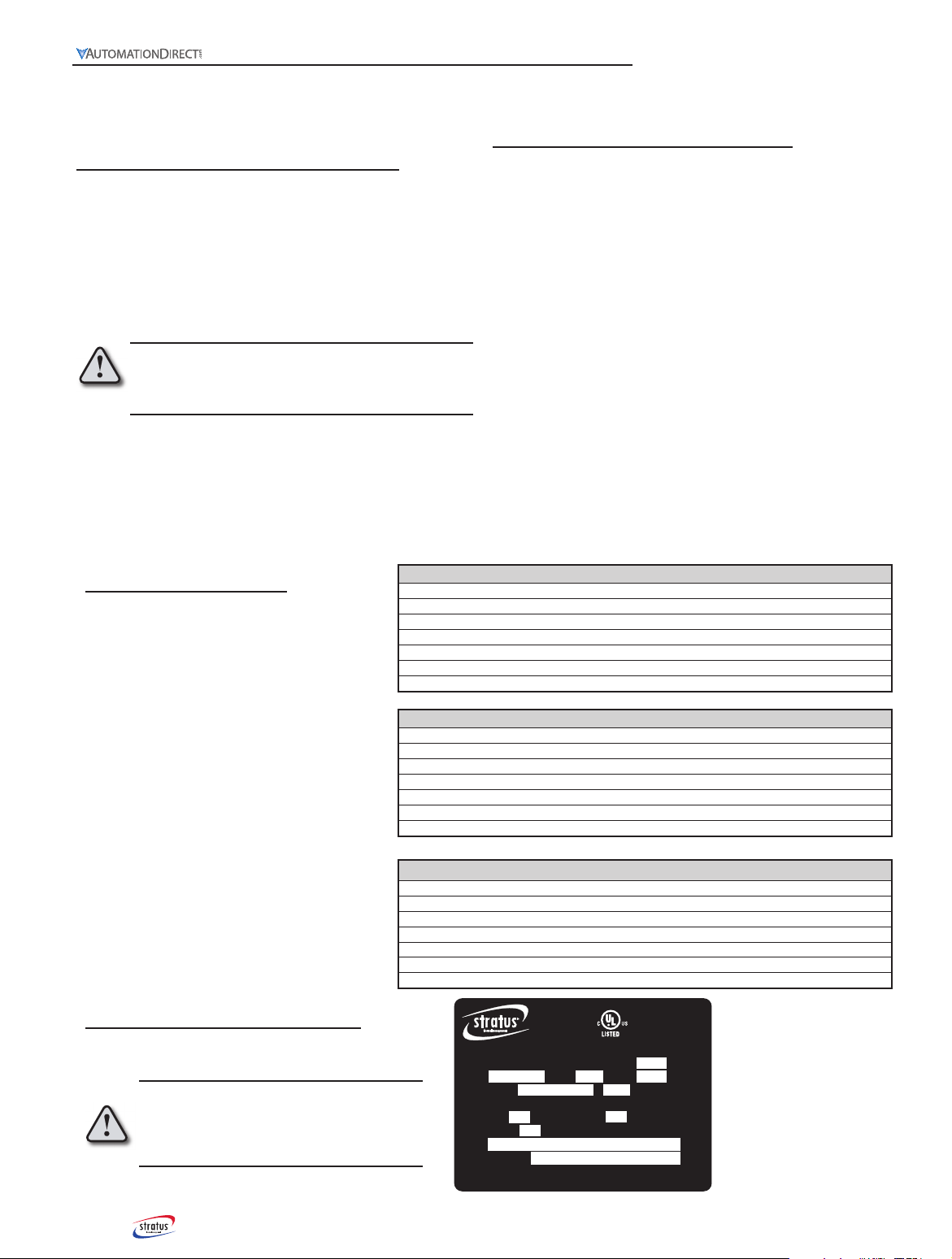
Volts Amps Phase Hz 60
Refrigerant Ounces
Design Pressure:
Low Side psi High Side psi
Motor-Compressor Thermally Protected
UL Type 12, 04, 4X Interface to Electronic Enclosure per UL 50 & 508a
Special Purpose
Air Conditioner
S/N
MODEL No.
BTU/H
NEMA Type
Automation Direct • 800.633.0405
www.automationdirect.com
UL File # SA33404
Input Specification
Refrigerant Type/Weight
Refrigerant Pressure
Enclosure Rating
A/C Unit Serial Number
A/C Unit Model Number
Nameplate Information
Be sure to record the data from the label onto the back
of the manual and keep in a safe place for warranty.
WARNING: Before operating the air conditioner,
inspect all electrical wiring to ensure proper
installation and wiring to the proper power source.
The minimum circuit amperage must be 125% of the
air conditioner label amperage listed for the voltage
selected.

7
www.automationdirect.com STRATUS TA10 Series Industrial Air Conditioners User Manual
2nd edition, Rev. C.
7
www.automationdirect.com
Basic Operation
The STRATUS air conditioner will lower the temperature
inside an enclosure to ensure its proper operational temperature.
STRATUS air conditioners, when sized properly, will provide
cooling as necessary, automatically controlled through the
digital temperature controller.
STRATUS air conditioners operate as a “closed loop” system
where the enclosure air is taken into the STRATUS air
conditioner and cooled, and then returned to the enclosure with
no exposure to, or introduction of, outside / ambient air. This
assures the enclosure is separated from, and not contaminated
with, ambient air, dirt, chemicals, dust, moisture or foreign
matter, so that sensitive enclosure components are protected
and kept cool / dehumidified. The STRATUS air conditioner
refrigeration cycle removes warm enclosure air and excess
humidity. The humidity condenses to liquid and then the
Condensate Removal System changes it back into vapor where
it is then vented to the atmosphere. In the event of excess water
where the enclosure door has been left open, there is an overflow
hole on the bottom of every unit.
The evaporator fan runs continuously to provide the required
climate control to the enclosure. The compressor turns on if
the enclosure temperature is greater than the factory setpoint of
95°F plus the temperature differential of 5°F. As the refrigerant
pressure builds to a factory setpoint, the condenser fan turns on
to force air flow across the coils. Refrigerant low pressure and
high temperature safety switches shut the compressor off if the
evaporator coil begins to ice up, if there are leaks in the system,
or if the condenser coil overheats. The temperature control
display will indicate an LED alarm indication ((!)) and specific
alarm, such as HA for high temperature alarm, or CA for low
pressure/low temperature alarm. After the compressor stops,
most alarm conditions will resolve (pressure will equalize) and
the snowflake LED on the temperature control will blink to
indicate that the compressor is off for the five minute anti-short
cycle time delay.
Refer to the Troubleshooting Guide for corrective action, as
the condition may repeat in 7-minute cycles. For 2 minutes
the alarm condition is bypassed to prevent nuisance trips.
Then, there is a 5-minute, anti-short cycle time delay before
the compressor is turned on.
The refrigerant thermal expansion valve assures optimum cooling
efficiency through a wide range of operating temperatures. It
requires no adjustment or maintenance.
STRATUS NEMA/UL type 4X stainless steel units and
NEMA/UL type 4 units come with condenser coils coated with
a cutting-edge, high efficiency, electrically applied, corrosion-
resistant coating.
Closed Loop Cooling
Thermal
Expansion
Valve
Evaporator
Coils
Evaporator
Fan
Compressor
Condensate
Removal
System Condenser
Coils
Thermal
Expansion
Valve
Evaporator
Compressor
Condenser
Refrigeration Cycle
1-800-633-0405
8STRATUS TA10 Series Industrial Air Conditioners User Manual
2nd edition, Rev. C. 1-800-633-0405
8
Features
• Active Evaporator Condensate Boil-Off System
• High Condenser Refrigerant Temperature Control
• Low Refrigerant Pressure Cut-out Switch
• Digital Temperature Control Thermostat
troubleshooting diagnostics
• Anti short-cycle Time Delay and Bypass Time Delay
• Condenser Fan Cut-in Control Pressure Switch
• Powder coated to prevent rust (NEMA/UL Type
12 and 4)
• Material: NEMA/UL Type 12, Type 4: 16-gauge cold
rolled steel chassis and shroud
• NEMA/UL Type 4x: 304 stainless steel chassis and
shroud
• Chassis and shroud seal system ensures closed loop air
circulation
• Condenser inlet air filter
• Thermal expansion valve provides high performance over
wide temperature range
• Internally insulated to minimize case heat loss
• Schrader valves on low AND high pressure service ports
• High efficiency performance = high BTU per KWH for
minimal electricity cost
• Auxillary alarm contacts as a standard
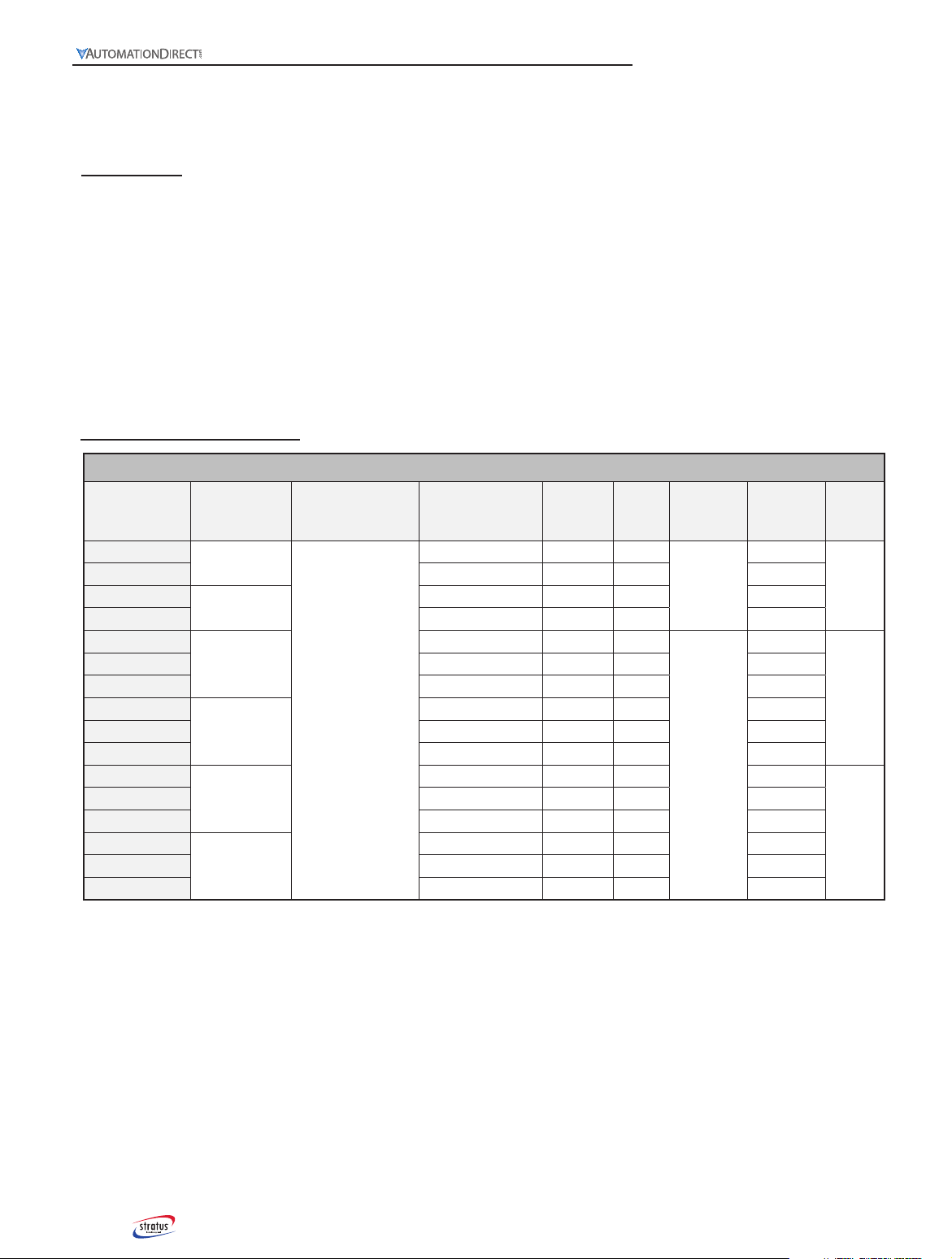
NEMA Type 12 Unit Specifications
Model
BTU/H @
Max. Ambient
Temperature
Standard Max.
Ambient Temperature Volts/Hertz Running
Amps
Unit
Weight
(lb)
Refrigerant
Type
Refrigerant
Amt. (oz)
Typical
Frame
Size
TA10-010-16-12 1000
125°F (51.67°C)
115/60 3.44 51
R134a
4.00
1
TA10-010-26-12 230/60 2.67 53 4.00
TA10-015-16-12 1500 115/60 3.44 51 7.75
TA10-015-26-12 230/60 2.67 53 7.75
TA10-020-16-12
2000
115/60 5.15 66
R422d
13.25
2
TA10-020-26-12 230/60 3.07 72 9.75
TA10-020-46-12 460/60 1.30 99 13.25
TA10-040-16-12
3000 - 4000
115/60 3.76 65 13.25
TA10-040-26-12 230/60 3.07 72 9.75
TA10-040-46-12 460/60 0.94 99 13.25
TA10-050-16-12
5000
115/60 7.26 97 12.50
3
TA10-050-26-12 230/60 3.76 92 12.50
TA10-050-46-12 460/60 1.86 136 12.50
TA10-060-16-12
6000 - 8000
115/60 7.83 97 18.00
TA10-060-26-12 230/60 4.80 98 18.00
TA10-060-46-12 460/60 1.80 142 18.00
Unit Specifications
* Voltage variation no greater than ± 10% from nameplate rating and Frequency variation no greater than ± 3Hz from nameplate
rating.

9
www.automationdirect.com STRATUS TA10 Series Industrial Air Conditioners User Manual
2nd edition, Rev. C.
9
www.automationdirect.com
NEMA Type 4X Unit Specifications
Model
BTU/H @
Max. Ambient
Temperature
Standard Max.
Ambient Temperature Volts/Hertz Running
Amps
Unit
Weight
(lb)
Refrigerant
Type
Refrigerant
Amt. (oz)
Typical
Frame
Size
TA10-010-16-4X 1000
125°F (51.67°C)
115/60 3.44 51
R134a
4.00
1
TA10-010-26-4X 230/60 2.67 53 4.00
TA10-015-16-4X 1500 115/60 3.44 51 7.75
TA10-015-26-4X 230/60 2.67 53 7.75
TA10-020-16-4X
2000
115/60 5.15 66
R422d
13.25
2
TA10-020-26-4X 230/60 3.07 72 9.75
TA10-020-46-4X 460/60 1.30 99 13.25
TA10-040-16-4X
3000 - 4000
115/60 3.76 65 13.25
TA10-040-26-4X 230/60 3.07 72 9.75
TA10-040-46-4X 460/60 0.94 99 13.25
TA10-050-16-4X
5000
115/60 7.26 97 12.50
3
TA10-050-26-4X 230/60 3.76 92 12.50
TA10-050-46-4X 460/60 1.86 136 12.50
TA10-060-16-4X
6000 - 8000
115/60 7.83 97 18.00
TA10-060-26-4X 230/60 4.80 98 18.00
TA10-060-46-4X 460/60 1.80 142 18.00
NEMA Type 4 Unit Specifications
Model
BTU/H @
Max. Ambient
Temperature
Standard Max.
Ambient Temperature Volts/Hertz Running
Amps
Unit
Weight
(lb)
Refrigerant
Type
Refrigerant
Amt. (oz)
Typical
Frame
Size
TA10-010-16-04 1000
125°F (51.67°C)
115/60 3.44 51
R134a
4.00
1
TA10-010-26-04 230/60 2.67 53 4.00
TA10-015-16-04 1500 115/60 3.44 51 7.75
TA10-015-26-04 230/60 2.67 53 7.75
TA10-020-16-04
2000
115/60 5.15 66
R422d
13.25
2
TA10-020-26-04 230/60 3.07 72 9.75
TA10-020-46-04 460/60 1.30 99 13.25
TA10-040-16-04
3000 - 4000
115/60 3.76 65 13.25
TA10-040-26-04 230/60 3.07 72 9.75
TA10-040-46-04 460/60 0.94 99 13.25
TA10-050-16-04
5000
115/60 7.26 97 12.50
3
TA10-050-26-04 230/60 3.76 92 12.50
TA10-050-46-04 460/60 1.86 136 12.50
TA10-060-16-04
6000 - 8000
115/60 7.83 97 18.00
TA10-060-26-04 230/60 4.80 98 18.00
TA10-060-46-04 460/60 1.80 142 18.00
Unit Specifications
* Voltage variation no greater than ± 10% from nameplate rating and Frequency variation no greater than ± 3Hz from nameplate
rating.
* Voltage variation no greater than ± 10% from nameplate rating and Frequency variation no greater than ± 3Hz from nameplate
rating.
1-800-633-0405
10 STRATUS TA10 Series Industrial Air Conditioners User Manual
2nd edition, Rev. C. 1-800-633-0405
10
Preliminary Testing
Before installing the STRATUS system on the enclosure, operate
the unit for 20 to 30 minutes to ensure it is functioning properly.
Although the unit has been tested at the factory, internal damage,
which may have not been apparent during the unpacking
inspection, may have occurred during shipping, .
• Place the system on a solid base, such as a workbench or table.
• 1000 and 1500 BTU/H units draw external cooling air from the
bottom and must be operated elevated.
• Check that the warm air system filter is in place. Location varies
with model - see dimensional drawings.
• Check the serial number label to be sure the electric power
available to the air conditioner is the proper voltage, phase and
amperes.
• Check electric power source for proper ground wire and
neutral wire installation.
• Check to verify that the electric power is protected by an
appropriately sized fuse or circuit breaker.
• As soon as power is supplied to the system, the cool air
evaporator fan will begin to operate. The compressor and warm
air condenser fan will not operate if the room air temperature is
below 100°F. This is because the programmable controller has
a factory setpoint of 95°F plus 5°F differential parameter (Hy).
The digital display on the face of the controller will be displaying
room temperature. If the display indicates 100°F or warmer, the
snowflake status LED will display and the compressor will
operate. The warm air condenser fan will come on shortly
after the compressor, when the refrigerant pressure builds to
approximately 300 psi. If the display indicates a temperature
less than 100°F, adjust the setpoint to a temperature lower than
the room temperature in order for the compressor and warm
air condenser fan to operate. Refer to the Digital Temperature
Controller section of this manual in order to change the factory
setpoints.
• With the compressor and both fans functioning, allow the unit
to operate for 20 to 30 minutes. This will provide sufficient
time for the vapor compression system to achieve equilibrium.
Measure the cool air outlet temperature with an accurate
thermometer. This temperature should be at least 10 degrees
colder than the inlet air temperature (if the room temperature
is warmer than 70°F). Inlet air temperature will be displayed
on the programmable controller. In areas of high humidity, the
temperature difference may be less than 10 degrees.
Note: Turn the unit off if any of the equipment makes any unexpected or hard mechani-
cal noises or vibrations, and refer to the Troubleshooting Guide.
Note: If the Digital Temperature Controller displays any alarms, refer to the Digital
Temperature Controller section.
• After completing the above check points, the electrical enclosure
is ready to be prepared for the installation of the STRATUS
AC unit.
Mounting the Air Conditioner
Caution: To prevent damage to the coils, use ONLY the mounting
bolts provided with the unit.
Using the template supplied, determine where the air
conditioner is to be mounted and make sure that all required
cuts and holes will not interfere with or damage the enclosure.
There must be 5” clearance between walls / obstructions and the
air conditioner so as not to restrict the condenser supply air and
return air flow. Restricted condenser air flow will affect the air
conditioner’s performance.
Caution: If mounting the air conditioner to the enclosure door,
confirm with the enclosure manufacturer that the door’s hinges
will support the air conditioner’s added weight (see equipment
specifications). Ensure that when the door is fully open, that the
enclosure will not topple over due to the off-center load.
Mount the air conditioner high on the enclosure in order to cool
the hot air in the top of the enclosure. Position the unit where the
cold air can circulate across the width of the enclosure to cool it all
the way across.
Once proper mounting placement is determined, turn the
enclosure equipment off, if possible, to prevent damage. Drill and
cut the holes as indicated on the actual size mounting template
included in the package. Install insulation gasket as required to
ensure an air-tight closed-loop seal. Hang the air conditioner on
the Easy Hang tabs.
From inside the enclosure, use the fasteners supplied to attach the
air conditioner to the enclosure. Tighten the bolts in stages so that
there is equal pressure at all points of attachment. Ensure that these
fasteners are tight so as to prevent the unit from falling off the
enclosure. These fasteners should be checked periodically to be
sure that they have not become loose because of vibration.
Verify that the power supplied is compatible with the air
conditioner’s power requirements provided on the air conditioner
serial number label. Properly connect to a circuit with a minimum
15 amp capacity circuit breaker and proper voltage and frequency.
Please check the specification label on the unit for exact amp
rating. Test the voltage at the power source for proper polarity and
good ground.
After mounting the air conditioner, replace / close the enclosure
door and start air conditioner; test for air leaks to assure a
proper closed air loop seal, and run-test the unit to assure proper
operation after mounting. If any cold air leaks are found, check
for proper mounting and apply silicone-free Lexel sealer if leaks
persist. Check that the air conditioner’s condenser inlet air filter is
installed properly and make sure it is cleaned regularly.
11
www.automationdirect.com STRATUS TA10 Series Industrial Air Conditioners User Manual
2nd edition, Rev. C.
11
www.automationdirect.com
System Operation
Once the STRATUS system has been installed onto the
enclosure and the power has been connected to a properly
grounded power source with adequate voltage and current
supply, the unit is ready for operation. As soon as electrical
power is supplied to the STRATUS system and the power
switch located on the back of the unit is turned on, the
evaporator fan will start to operate. The fan will run
continuously so that the controller can monitor the enclosure’s
internal temperature. The enclosure temperature will be
displayed on the face of the controller. If the enclosure
temperature is greater than the cooling setpoint of 95°F plus
factory-set temperature differential of 5°F, the snowflake status
LED will be ON and the compressor will turn on. After the
refrigerant pressure builds up to a factory setpoint of 300 psi,
the condenser fan will operate.
This signifies that the cooling system has begun operation to
remove heat and humidity from the enclosure. If the heat
load within the enclosure is less than the cooling capacity of
the STRATUS system, the temperature on the digital display
will begin to drop. When the temperature inside the enclosure
drops to the factory-set 95°F setpoint, the compressor will
cycle off. The cool air evaporator fan will continue to operate,
circulating air within the enclosure. The compressor fan will
cycle off if the pressure drops below the factory setpoint.
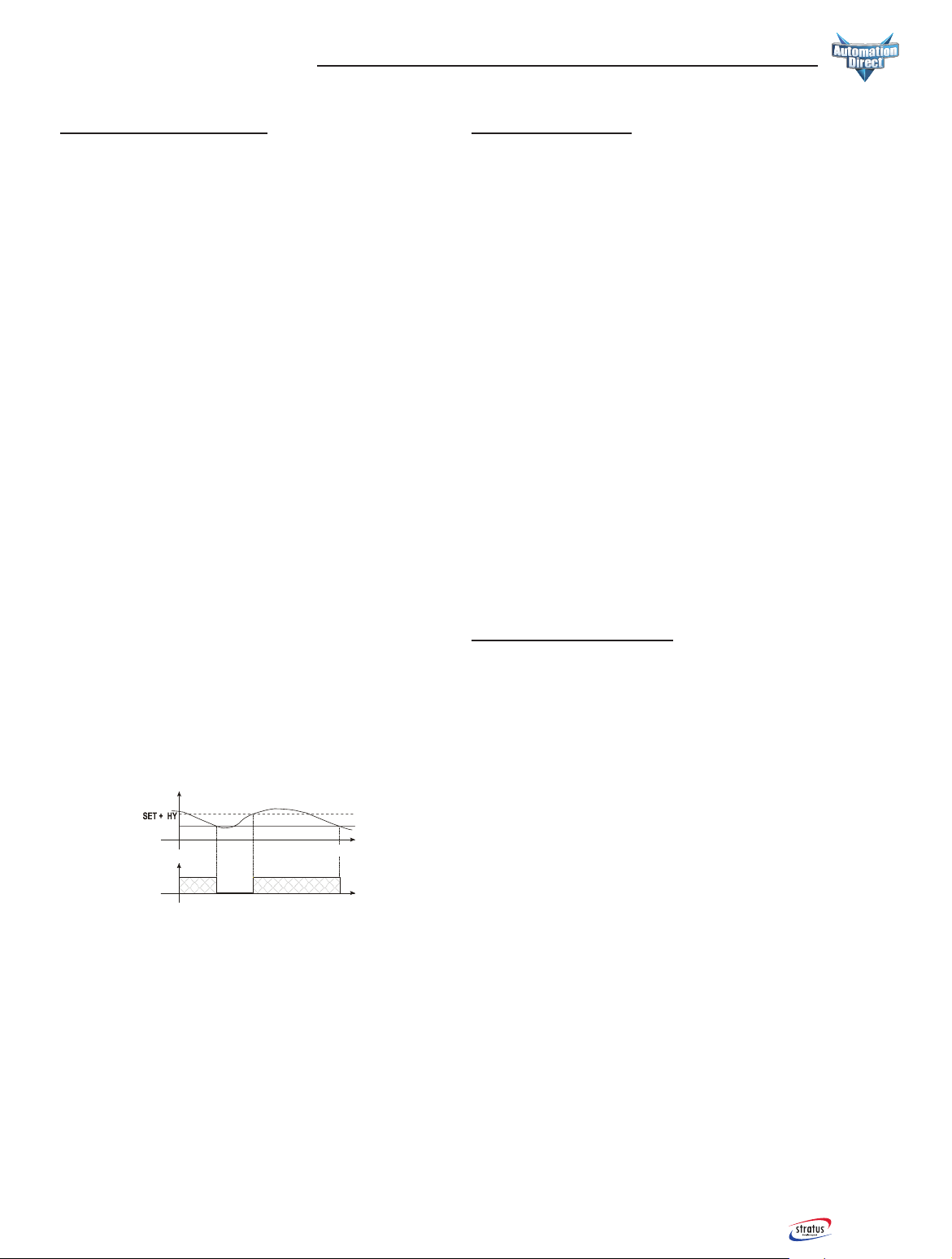
Example: “Cooling on” @ 100°F; “Cooling off” @ 95°F.
Set point is 95°F plus 5°F Hysteresis= Cooling on @ 100°F.
If the compressor attempts to cycle within 5 minutes, the
snowflake status LED will FLASH. This indicates that the
compressor’s automatic timer is working (the anti-short-cycle
timer is factory set at 5 minutes). At the end of 5 minutes, the
compressor will begin to operate and the snowflake status LED
will remain ON while the compressor remains on.
System Faults
If any of the critical control parameters exceed limits, the
compressor is turned off, an alarm condition is indicated on
the front panel, and an alarm contact (Form C) operates for
remote alarming.
Three main conditions can shut down the AC compressor
down:
• The condenser high temperature alarm
• The evaporator coil alarm
• The compressor thermal overload
In the event that the condenser coil overheats, a condenser high
temperature alarm, HA2, will flash on the display of the digital
temperature controller, the remote alarm contact will operate,
and the compressor will turn off after a 3-minute time delay.
In the case that the evaporator coils ice up or there is a leak,
an evaporator coil alarm, CA, will flash on the display of the
Digital Temperature Controller, the remote alarm contact will
operate, and the compressor will turn off after a 2-minute time
delay.
A thermal overload protects the compressor against faults. In
the event that the snowflake status LED is not flashing on the
display and the compressor is not running, an internal fault
may have occurred on the unit. Refer to the Troubleshooting
Guide in this manual.
Alarm Conditions
If any of the alarm parameters exceed limits, an alarm condition
is indicated on the front panel and an alarm contact (Form C)
operates for remote alarming.
The temperature alarms are delayed for 30 minutes at initial
startup. If the preset high temperature limit is exceeded for
more than 3 minutes, the compressor continues to operate but
there is a maximum temperature alarm, HA, flashing on the
display.
If the preset low temperature limit of 45°F is exceeded for
more than 3 minutes, there is a minimum temperature alarm,
LA, flashing on the display. (The compressor turns off at the
temperature setpoint.)
In case of a fault in the enclosure temperature probe “P1”,
the start and stop of the compressor are delayed for 5 and 15
minutes, respectively. A P1 alarm will display and the remote
alarm contact will operate immediately.
In case of a fault in the condenser temperature probe “P2”, a
P2 alarm will flash on the display and the remote alarm contact
will operate immediately.
If the evaporator coil pressure drops below 10 psi for more
than 2 minutes, there is an evaporator coil alarm, CA, and the
compressor turns off. After the pressure is increased to 25 psi,
the CA alarm is cleared and the compressor operates after a
5-minute time delay.
Time
Temperature
Compressor
SET
ON
1-800-633-0405
12 STRATUS TA10 Series Industrial Air Conditioners User Manual
2nd edition, Rev. C. 1-800-633-0405
12
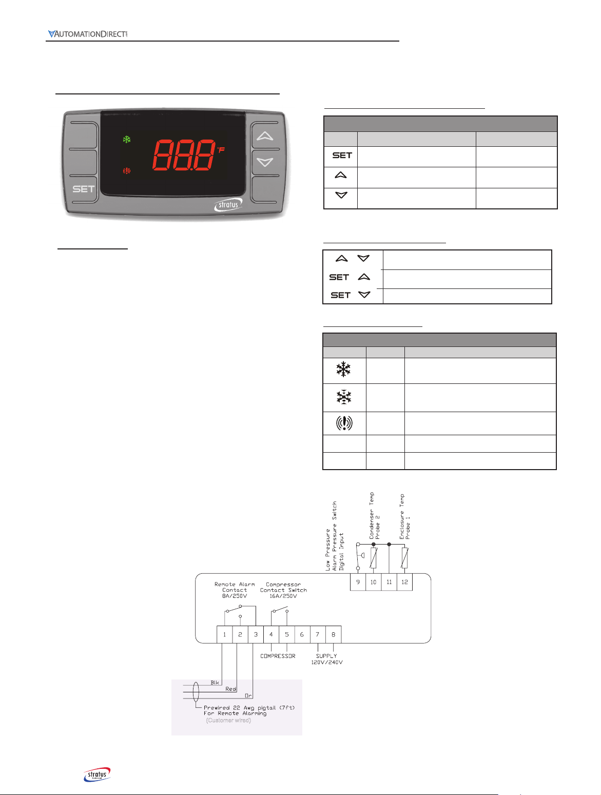
Front Panel Commands
Symbol Visual Mode Programming Mode
To display target setpoint in memory.
Hold >2 sec to enter Programming Mode
Selects or confirms an
operation
(UP): To display maximum temperature
setpoint in memory
Displays parameters or
increases value
(DOWN): To display minimum temperature
setpoint in memory
Displays parameters or
decreases value
To lock and unlock the keyboard
+To return to the room temperature display
+
To enter programming mode
+
FRONT PANEL COMMANDS
KEY COMBINATIONS
LED FUNCTIONS
LED Functions
LED MODE FUNCTION
ON Compressor enabled
Flashing Anti short-cycle delay enabled
ON An alarm is occurring (CA or HA)
°F ON Measurement unit
°F Flashing Programming phase
Digital Temperature Controller
Overview
The microprocessor-based digital temperature controller
performs the functions of controlling the enclosure
temperature while monitoring operating limits and refrigerant
pressures. Temperature and alarm status are indicated
on the front panel in easy-to-read LEDs (0.57”x 0.29”
[14.5mm x 7.3mm]). It also records the maximum and
minimum temperatures within the enclosure.
The controller includes a compressor anti short-cycle time
delay (Parameter AC = 5 minutes) for compressor protection.
A factory-set bypass time delay of 2 minutes prevents nuisance
trip-outs caused by cold weather startups and transient high
temperature limits.
The inputs include one enclosure temperature probe (NTC
input), one condenser coil temperature probe (NTC input)
and one low pressure switch digital input. Select parameters
(listed in the setpoint table) are configurable through the
keypad.
(Customer wired)

13
www.automationdirect.com STRATUS TA10 Series Industrial Air Conditioners User Manual
2nd edition, Rev. C.
13
www.automationdirect.com
Functions and Parameters
Temperature Controller Setpoints
Function Operation Parameter Operating Range Factory Set
Point
Cooling Setpoint Set cooling relay SET 70 to 95°F 95°F
Cooling Differential Control hysteresis Hy 1 to 45°F 5°F
Compressor Protection Anti short-cycle AC 0 to 50 minutes 5 minutes
*Probe Displayed
Selects display probe
P1 - Enclosure Temp
P2 - Condenser Temp
Lod P1, P2, P3, P4 P1
Max Temp Alarm Panel Indicator ALU 45 to 302°F 105°F
Min Temp Alarm Panel Indicator ALL -67 to 105°F 45°F
*Note: P3 and P4 are not used and if selected will result in noP flashing on the display.
Main Functions
1. Press and immediately release the SET key. The display will show the setpoint value.
2. Press and immediately release the SET key or wait for 15 seconds to display the probe value again.
1. Press the SET key for more than 2 seconds to change the setpoint value.
The value of the setpoint will be displayed and the FLED starts blinking.
2. To change the SET value, press the UP or DOWN arrow key within 15 seconds.
3. To store the new setpoint value, press the SET key again or wait 15 seconds.
NOTE: The set value is stored even when the procedure is exited by waiting for the time-out to expire.
To change the parameter’s value, operate as follows:
1. Enter the Programming mode by pressing the SET + DOWN arrow keys for 3 seconds. The FLED starts blinking.
2. Select the required parameter by pressing the UP or DOWN arrow key. Press the SET key to display its value.
3. Press the UP or DOWN arrow key to change its value.
4. Press SET to store the new value and move to the following parameter.
To exit: Press SET + UP arrow keys or wait 15 seconds without pressing a key.
NOTE: The set value is stored even when the procedure is exited by waiting for the time-out to expire.
1 .Press and hold the SET and DOWN arrow keys simultaneously for more than 3 seconds. (The °F LED starts blinking.)
2. Release the keys, then push the SET and DOWN arrow keys simultaneously , again for more than 7 seconds.
The Pr2 label will be displayed immediately followed by the HY parameter.
3. Select the required parameter.
4. Press the SET key to display its value.
5. Press the UP or DOWN arrow to change its value.
6. Press SET to store the new value and move to the following parameter.
To exit: Press SET + UP arrow keys or wait 15 seconds without pressing a key.
NOTE 1: If no parameter is present in Pr1, after 3 seconds the noP message is displayed. Keep the keys pushed until the Pr2 message is displayed.
NOTE 2: The set value is stored even when the procedure is exited by allowing the time-out to expire.
1. Press and hold the UP and DOWN arrow keys simultaneously for more than 3 seconds.
2. The POF message will be displayed and the keyboard will be locked.
At this point, it will be possible only to see the setpoint or the MAX or MIN temperature stored.
If a key is pressed for more than 3 seconds the POF message will be displayed.
1. Press and hold the UP and DOWN arrow keys simultaneously for more than 3 seconds until the Pon message is displayed.
HOW TO SEE THE SETPOINT
HOW TO CHANGE THE SETPOINT
HOW TO CHANGE THE AC, Lod, ALU AND ALL PARAMETERS
HOW TO CHANGE THE DIFFERENTIAL VALUE (Hy)
HOW TO LOCK THE KEYBOARD
HOW TO UNLOCK THE KEYBOARD

1-800-633-0405
14 STRATUS TA10 Series Industrial Air Conditioners User Manual
2nd edition, Rev. C. 1-800-633-0405
14
Maximum and Minimum Temperature
1. Press and release the DOWN arrow key.
The Lo message will be displayed followed by the minimum temperature recorded.
2. By pressing the DOWN arrow key again or waiting 5 seconds, the normal display will be restored.
1. Press and release the UP arrow key.
The Hi message will be displayed followed by the maximum temperature recorded.
2. By pressing the UP arrow key again or waiting 5 seconds, the normal display will be restored.
1. Press and hold the SET key for more than 3 seconds, while the maximum or minimum temperature is displayed. (rSt message will be displayed)
2. To confirm the operation, the rSt message will blink and the normal temperature will be displayed.
Alarm Signals
Message Cause Outputs
P1 Enclosure probe failure Alarm relay operates; start and stop of the compressor after 15-minute intervals
P2 Condenser probe failure Alarm relay operates
HA Maximum temperature alarm: P1 L 105°F for 3 minutes (after initial 30 min. delay) Alarm relay operates
LA Minimum temperature alarm: P1 l 45°F for 3 minutes (after initial 30 min. delay) Alarm relay operates
HA2 Condenser high temperature: P2 L 145°F for 3 minutes Alarm relay operates, compressor off
LA2 Condenser low temperature: P2 l 50°F for 3 minutes Alarm relay operates
CA Evaporator coil alarm: low pressure for 2 minutes Alarm relay operates, compressor off
noP Invalid probe selected: low evaporator coil No outputs, display only
If the compressor is turned off due to an alarm, it will be able to restart after the AC anti short-cycle time delay. (Parameter AC = 5 minutes)
Probe alarm P1 is cleared with no time delay after the fault is cleared.
Probe alarm P2 starts and stops with no time delay.
Temperature alarm HA automatically clears as soon as the temperature returns to below 105°F (the ALU setpoint) - 2°F = 103°F.
Temperature alarm LA automatically clears as soon as the temperature returns to above 45°F (the ALL setpoint) + 2°F.
Temperature alarm HA2 automatically clears as soon as the condenser coil temperature returns to below 135°F.
Temperature alarm LA2 automatically clears as soon as the condenser coil temperature returns to above 60°F
Temperature alarm CA automatically clears as soon as the pressure returns to normal.
ALARM RECOVERY
ALARM SIGNALS
HOW TO SEE THE MINIMUM TEMPERATURE
HOW TO SEE THE MAXIMUM TEMPERATURE
HOW TO RESET THE MAX AND MIN TEMPERATURE RECORDED
Functions and Parameters
15
www.automationdirect.com STRATUS TA10 Series Industrial Air Conditioners User Manual
2nd edition, Rev. C.
15
www.automationdirect.com
Preventative maintenance
Before performing any maintenance, turn off power to the unit.
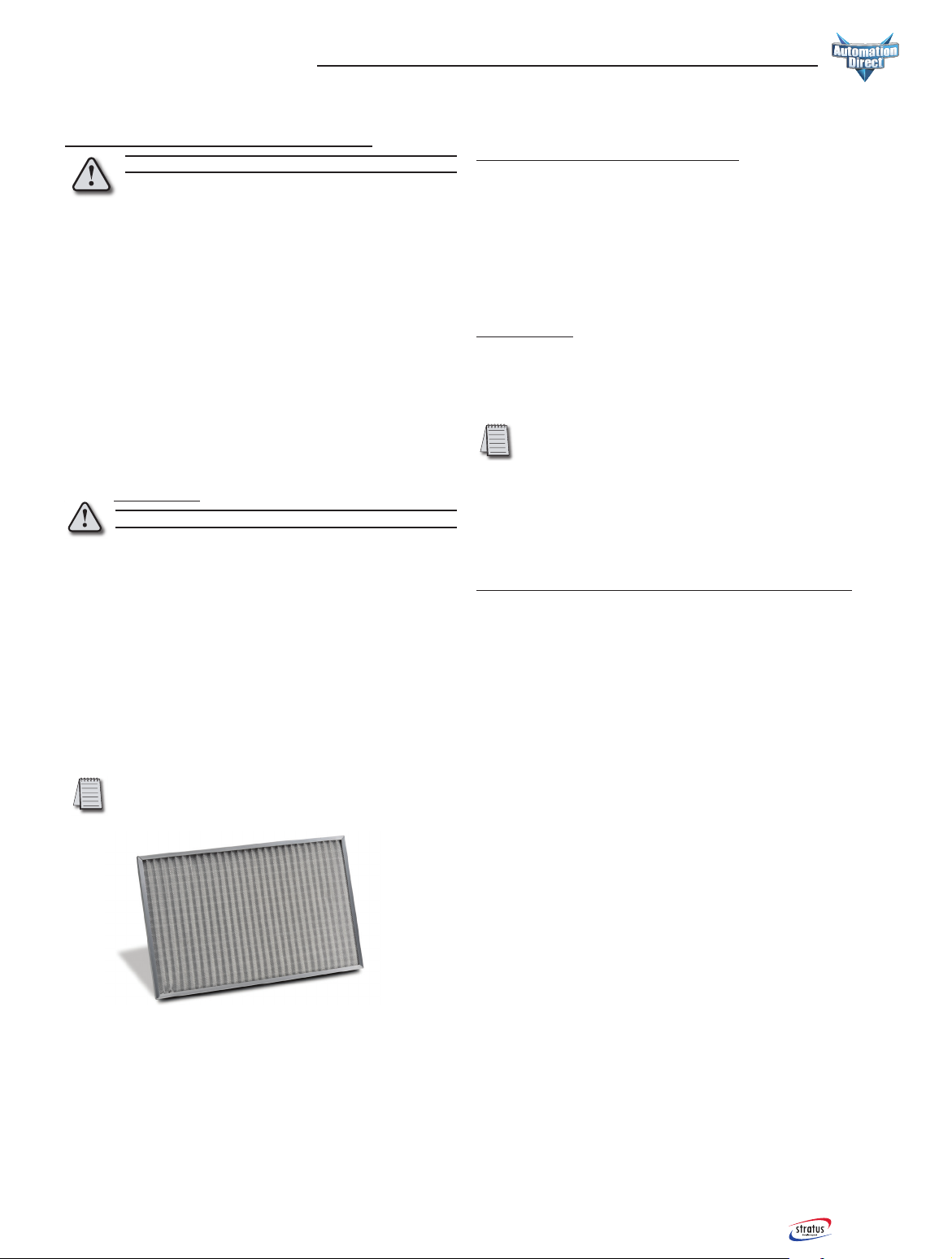
Air conditioners require regular cleaning of the
condensingairinletfilter.Washthefilteroften,andback-
flush the dirt out; or replace, if not washable, whenever it appears
physically dirty. Restriction to the flow of air over the condenser
coil will degrade the performance of the equipment, cause it to
overheat, reduce cooling and can damage the compressor.
The compressor protection system will cycle the unit off if
the condenser temperature is too high or the compressor is
otherwise overloaded.
Restricted air flow due to neglecting a dirty filter will cause the
unit to safety off and then turn back on after it cools off, over
and over (cycling). Operation in this overheat/shut down/cool
down/restart mode will damage the equipment and void the
warranty.
Air Filter Service
Before performing any maintenance, turn off power to the unit.
Removetheairconditionerfilterandwash,orreplaceifnot
washable. Dry thoroughly before replacing. Order replacement
filters by frame size (TA10-FILTER-1, TA10-FILTER-2 or
TA10-FILTER-3) from AutomationDirect. DO NOT operate
the air conditioner without the air filter. Such operation will
allow the condensing coil to become dirty and lose efficiency,
causing overheating and diminished cooling capacity. Dirty
condensing coils must be back-flush cleaned using proper
commercial coil cleaning compounds and thorough back-
flush rinsing. Refer to directions on the cleaning compounds
selected. Acid wash is not recommended as it reduces the life
of the coil.
Note: Do not use solvents to clean the programmable thermostat.
Wipe with mild soap and water.
Condenser and Evaporator Fans:
STRATUS air conditioners use high efficiency, long life
(high duty cycle), high tech, ball bearing fans engineered for
optimum performance. The bearings are sealed and require no
maintenance. Keep fan blades clean for optimal performance.
Before performing any maintenance, turn off power to
the unit. Fans are removable and powered through plug-in
connections.
Compressor
STRATUS uses hermetically factory sealed compressors that
are quiet, low vibration and are maintenance-free. Overheat
sensors are installed to protect the compressor from damage
due to overheating.
Note: The rotary compressor runs with compressed refrigerant gas on the
outer case and therefore is hot to the touch.
STRATUS air conditioners are meticulously leak-tested
and run-tested after assembly. If a leak in the system should
develop due to shipping damage or mechanical vibration, the
leak must be detected, repaired and the refrigerant charge
restored to the system by a qualified refrigeration professional.
Moving the Enclosure and the Air Conditioner
If the enclosure the STRATUS air conditioner is mounted to
must be moved, remove the air conditioner from the enclosure
and move the air conditioner and enclosure separately. Moving
an enclosure with the air conditioner mounted may damage
the enclosure and the air conditioner and void the warranties.
Replacement filters are available (purchase separately)
for each of the three Stratus air conditioner frame sizes.

1-800-633-0405
16 STRATUS TA10 Series Industrial Air Conditioners User Manual
2nd edition, Rev. C. 1-800-633-0405
16
TROUBLESHOOTING GUIDE
COMPLAINT SYMPTOM PROBABLE CAUSE ACTION
Unit will not run Controller not on
Evaporator fan not on
No power Check circuit breaker. Check voltage at power source. Power must match unit
requirements, 15 Amps min.
Unit power switch off Check rocker switch inside panel.
Compressor
stalls on startup
Compressor hums for 3 -5 seconds
then trips Insufficient power under load Check power source, wiring and circuit breaker capacity using power quality
meter.
CB on overload
Defective or disconnected run capacitor Have qualified A/C tech test and replace.
Faulty compressor Have qualified A/C tech test winding impedance.
Replace compressor if defective.
Controller on LED/Snowflake not on Check programmed setpoint and indicated temperature.
LED/Snowflake blinking Unit off on anti-short cycle time delay - clears after 5 minutes.
Evaporator fan not running Defective evaporator motor Have qualified A/C tech clean, repair or replace.
Evaporator running
CA alarm displayed
Setpoint too low Adjust temperature setpoint.
Low ambient Warm unit/Install low ambient crankcase heater.
Evaporator coil frozen Thaw and clean coil. Check for clogged drain. If enclosure obstruction causing
air re-circulation, remove obstruction.
Low refrigerant Have qualified A/C tech check.
Unit runs but
does not cool
properly
Compressor cycling Cycling on set point Reprogram setpoint or increase Hy.
HA2 alarm intermittent
Dirty condenser Clean condenser coil.
Condenser air flow blocked Installation must meet minimum clearance for condenser air flow.
Adjacent unit heating air Install baffle/deflector or move unit(s).
Perform touch test:
Compressor hot (190°F)
Suction accumulator cold ( 50 to 65°F)
Good condenser Have qualified A/C tech check evaporator section.
Restricted air flow Clean evaporator.
Recirculating air flow Remove restriction/Install baffle/Install fan.
Unit vibrating or
noisy Noise
Possible freight damage Inspect all points of mechanical contact between tubing and shroud or chassis.
Tube rattling against shroud
Compressor rattling against shroud Inspect compressor mounting.
Foreign object in fan/blower Clean blowers; tie-wrap any loose wiring. Replace air filter to prevent
recurrence.
Broken or bent fan blade Replace blower unit or fan blade.
High refrigerant pressure due to dirty air filter,
blocked or recirculating condenser air flow or
dirty condenser
Test air temperature entering and leaving condenser. Entering should equal
ambient. Leaving should equal entering + 15 degrees. Clean condenser with
degreaser and low pressure rinse. Clean or replace filter.
Condensate
draining from
overflow
Drains during normal operation Door partially open or air leaks between unit
and enclosure
Check door gasket and gasket compression on closing.
System must be closed loop.
Condensate
draining inside
unit
Water leaking out around compressor Blockage in evaporator drain lines prevents
water getting to the boil-off pan.
Clean condensate drains with degreaser. Check for crushed or blocked drain
lines. Clean evaporator coil and check for source of contamination.
Iced-up evaporator coil Defective evaporator blower Have qualified A/C tech clean, repair or replace.
Low refrigerant Have qualified A/C tech check level.
Troubleshooting Guide
17
www.automationdirect.com STRATUS TA10 Series Industrial Air Conditioners User Manual
2nd edition, Rev. C.
17
www.automationdirect.com
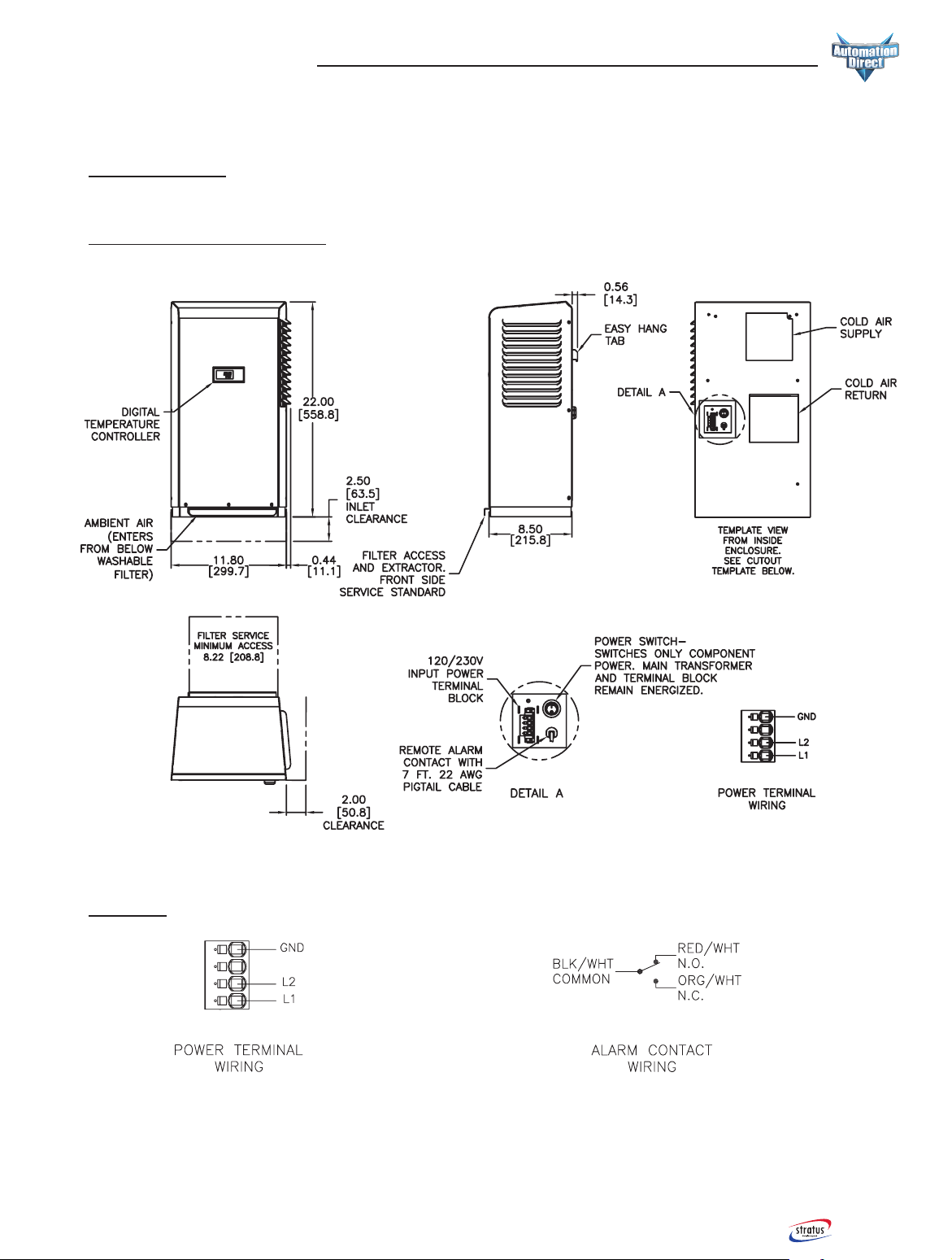
Typical Frame Size 1
1000 and 1500 BTU/H Units
Dimensions
All dimensions inches [millimeters]
Wiring

1-800-633-0405
18 STRATUS TA10 Series Industrial Air Conditioners User Manual
2nd edition, Rev. C. 1-800-633-0405
18
Cutout for Typical Frame Size 1
1000 and 1500 BTU/H Units
Dimensions
All dimensions inches [millimeters]

19
www.automationdirect.com STRATUS TA10 Series Industrial Air Conditioners User Manual
2nd edition, Rev. C.
19
www.automationdirect.com
Typical Frame Size 2
2000 and 3000 - 4000 BTU/H Units
Dimensions
All dimensions inches [millimeters]
Wiring

1-800-633-0405
20 STRATUS TA10 Series Industrial Air Conditioners User Manual
2nd edition, Rev. C. 1-800-633-0405
20
Cutouts for Typical Frame Size 2
2000 and 3000 - 4000 BTU/H Units
Dimensions
120 and 240V
480V
All dimensions inches [millimeters]
This manual suits for next models
16
Table of contents


