STREIVOR DemandAire Bronze User manual

Striving for Excellence
Photo to Come
DemandAire Bronze
Kitchen Ventilation Control System
www.streivor.com
Installation and Operations Manual

2
Streivor DemandAire Bronze Control Panel Installation and Operations Manual
2150 Kitty Hawk Road, Livermore, CA 94551 | (925) 960-9090 | Fax: (925) 960-9055
General Information
Acronyms ................................................................................................................................................................................3
Pre-Installation Precautions ....................................................................................................................................................4
DemandAire Control Panel Drawing Sample ..........................................................................................................................4
DemandAire Control Panel: Hood Mounted ...........................................................................................................................5
DemandAire Control Panel: Wall Mounted .............................................................................................................................5
Installation Procedures
Control Circuit Input Power Wiring..........................................................................................................................................6
Motor Circuit Input Power Wiring (Motor Starters Provided by Streivor) ................................................................................6
Motor Circuit Output Power Wiring (Motor Starters Provided by Streivor) .............................................................................7
Overload Setting (Motor Starters Provided by Streivor)..........................................................................................................7
Recommended Overload Setting for Single-Phase Motors....................................................................................................8
Recommended Overload Setting for Three-Phase Motors.....................................................................................................8
Fan Control Signal Wiring (Motor Starters Not Provided by Streivor) .....................................................................................8
Light Power Circuit Wiring.......................................................................................................................................................9
Internal Hood Fan (IHF) Power Circuit Wiring for SmartAire Technology Hoods ....................................................................9
Fire Suppression System (FSS) Switch Circuit Wiring ..........................................................................................................10
Ambient Resistance Temperature Detector (ARTD) Wiring ...................................................................................................11
Hood Canopy and/or Duct Collar Temperature Monitor Wiring ............................................................................................12
Optional: Shunt Trip Breaker Wiring......................................................................................................................................13
Optional: Modbus TCP Communication Wiring ....................................................................................................................13
Electric Gas Valve Input Power Wiring ..................................................................................................................................14
Electric Gas Valve Output Power Wiring ...............................................................................................................................14
Operation Procedures
Start Up .................................................................................................................................................................................15
Human Machine Interface (HMI) Touch Screen Control........................................................................................................15
Home Screen.........................................................................................................................................................................15
Customer Service Screen......................................................................................................................................................16
System Information Screen ..................................................................................................................................................16
Temperature Status Screen...................................................................................................................................................16
Fan Motor Status Screens.....................................................................................................................................................16
Secure Settings .....................................................................................................................................................................17
Temperature Dierential Settings Screen (Management) ......................................................................................................17
Timer Settings (Management) ...............................................................................................................................................17
Fire Suppression System Settings (Management) ................................................................................................................18
USB Removal Screem...........................................................................................................................................................18
Restore Factory Settings (Management)...............................................................................................................................18
Electrical Gas Valve Reset Relay...........................................................................................................................................19
Alarms ...................................................................................................................................................................................20
Temperature Monitor Alarm...................................................................................................................................................20
High Temperature Alarm........................................................................................................................................................20
Fan Motor Overload Alarm ....................................................................................................................................................20
Fire Suppression System Alarm ............................................................................................................................................21
Warranty
Warranty Information.............................................................................................................................................................22
Table of Contents

3
Streivor DemandAire Bronze Control Panel Installation and Operations Manual
2150 Kitty Hawk Road, Livermore, CA 94551 | (925) 960-9090 | Fax: (925) 960-9055
Acronyms
ARTD Ambient Resistance Temperature Detector
BMS Building Management System
CKV Commercial Kitchen Ventilation
DCKV Demand Control Kitchen Ventilation
DCP DemandAire Control Panel
EC Electronically Commutated
ECM Exhaust Collar Mounted
FSS Fire Suppression System
HCM Hood Canopy Mounted
HMI Human Machine Interface
IHF Internal Hood Fan
MBD Motorized Balance Damper
MUA Make Up Air
PLC Programmable Logic Controller
RTD Resistance Temperature Detector
VFD Variable Frequency Drive
General Information

4
Streivor DemandAire Bronze Control Panel Installation and Operations Manual
2150 Kitty Hawk Road, Livermore, CA 94551 | (925) 960-9090 | Fax: (925) 960-9055
General Information
Pre-Installation Precautions
Hood, Electrical, and Rough-In Schedules Field Wiring Diagram
Equipment Layout and Electrical Conduit RoutingInstallation Details
Serial
Number
DemandAire Control Panel Drawing Sample
WARNING
PRIOR TO MAKING ANY ELECTRICAL CONNECTIONS TO THE CONTROL PANEL, READ AND
UNDERSTAND THIS ENTIRE INSTALLATION AND OPERATIONS MANUAL. ALL WORK ON THE
CONTROL PANEL SHOULD BE PERFORMED BY QUALIFIED CONTRACTORS IN ACCORDANCE WITH
ALL APPLICABLE PREVAILING CODES AND STANDARDS.
THE CONTROL PANEL HAS MULTIPLE ELECTRICAL CONNECTIONS. VERIFY THAT ALL POWER HAS
BEEN DISCONNECTED TO THE CONTROL PANEL PRIOR TO WORKING ON OR NEAR THE CONTROL
PANEL. LOCK OUT / TAG OUT ALL OF THE DISCONNECT SWITCHES OR CIRCUIT BREAKERS TO
PREVENT ACCIDENTAL POWER UP.
ALL ELECTRICAL WIRING AND CONNECTIONS TO THE CONTROL PANEL SHALL BE IN ACCORDANCE
WITH THE PREVAILING CODES, THE NATIONAL ELECTRICAL CODES, AND ANSI/NFPA70.
VERIFY THAT THE SERIAL NUMBER ON THE WIRING DIAGRAM (SEE SAMPLE DRAWING) PROVIDED
WITH THE CONTROL PANEL MATCHES THE SERIAL NUMBER OF THE CONTROL PANEL BEFORE
USING THE WIRING DIAGRAM FOR REFERENCE.
VERIFY THAT THE VOLTAGE AND WIRE AMPERAGE CAPACITY AND WIRE INSULATION IS IN
ACCORDANCE WITH THE CONTROL PANEL NAMEPLATE.
5
Streivor DemandAire Bronze Control Panel Installation and Operations Manual
2150 Kitty Hawk Road, Livermore, CA 94551 | (925) 960-9090 | Fax: (925) 960-9055
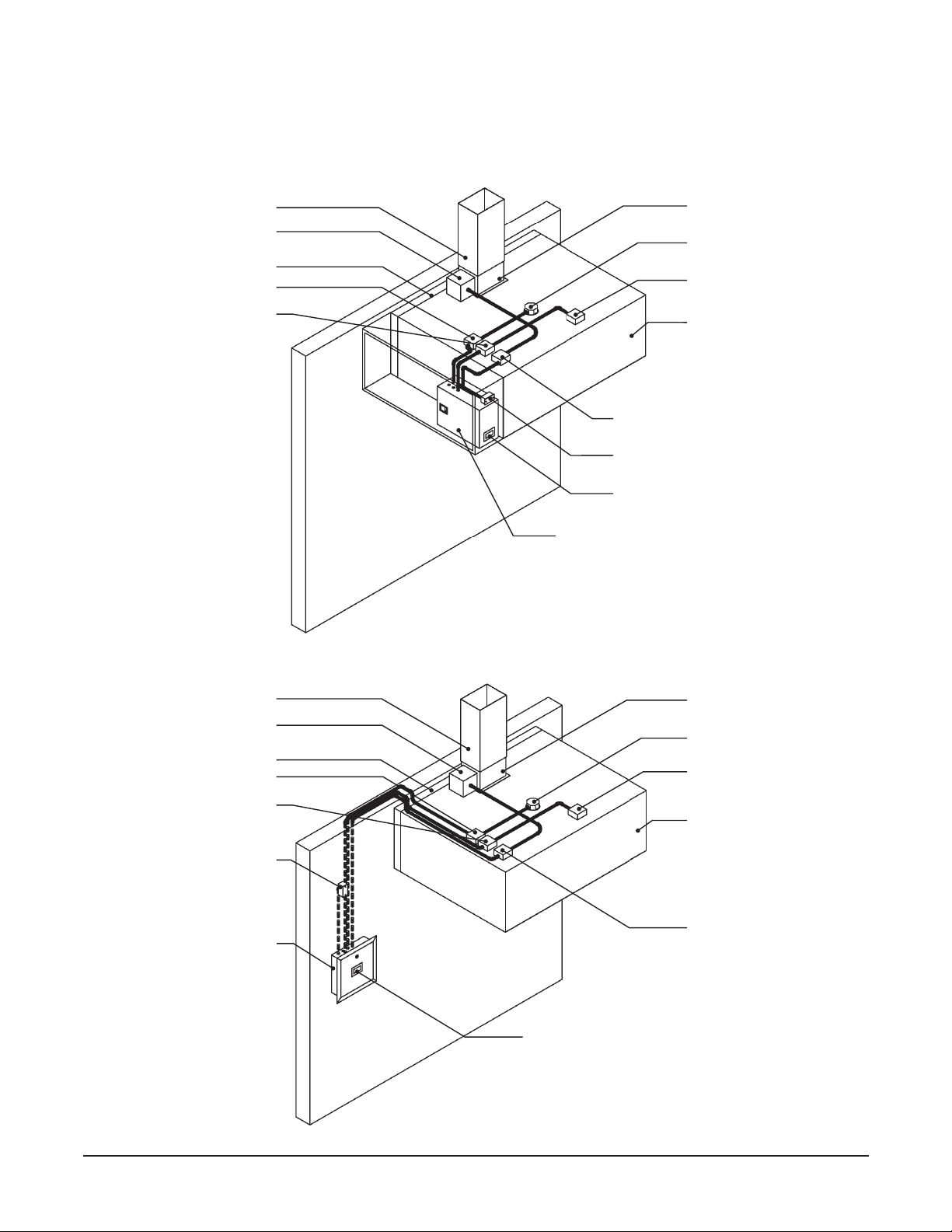
Wall Mounted DemandAire
Control Panel (Recessed)
Hood Duct Collar Access Enclosure
with Temperature Monitor Hood Light Fixture J-Box
Hood Light Fixture J-Box
SmartAire Internal Hood
Fan J-Box (optional)
SmartAire Internal Hood
Fan J-Box (optional)
Temperature Monitor J-Box (optional)
Temperature Monitor J-Box
(Optional)
Hood Light Power J-Box
Hood Light Power J-Box
SmartAire Internal Hood Fan
Power J-Box (optional)
SmartAire Internal Hood Fan
Power J-Box (optional)
Remote Ambient
Temperature Monitor
General Information
Exhaust Duct
Exhaust Duct
Rear Stando
Rear Stando
Hood Canopy
Hood Canopy
Hood Duct Collar
Hood Duct Collar
DemandAire Control Panel: Hood Mounted
DemandAire Control Panel: Wall Mounted
Cabinet Mounted Human Machine
Interface
Cabinet Mounted Ambient Temperature
Monitor
Hood Duct Collar Access Enclosure
with Temperature Monitor
Cabinet Mounted DemandAire Control
Panel
Control Panel Mounted
Human Machine Interface
6
Streivor DemandAire Bronze Control Panel Installation and Operations Manual
2150 Kitty Hawk Road, Livermore, CA 94551 | (925) 960-9090 | Fax: (925) 960-9055
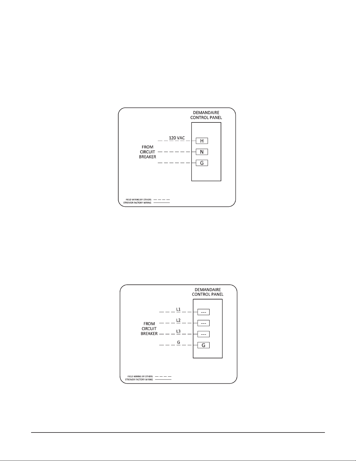
Control Circuit Input Power Wiring
a. Verify that all supply power to the control panel is locked out and tagged out.
b. Verify that the circuit breaker amperage is sized correctly for the control circuit per the DemandAire Control Panel
(DCP) drawings.
c. Connect 120 VAC single phase power to the terminal blocks in the control panel labeled H, N, and Ground (Figure 1).
d. The wires should be torqued to 0.6-0.8 N•m at the terminal blocks.
Motor Circuit Input Power Wiring (Motor Starters Provided by Streivor)
a. Verify that all power to the control panel is locked out and tagged out.
b. Verify that the circuit breaker amperage is sized correctly for each motor input power circuit.
c. Verify that the voltage and phase of each motor circuit is correct per the DCP drawings.
d. Connect input power to the input power terminal blocks as shown on the DCP drawings (Figure 2).
e. The wires should be torqued to 1.5-1.8 N•m at the terminal blocks.
FIGURE 1: Control Circuit Input Power
Installation Procedures
FIGURE 2: Motor Circuit Input Power
7
Streivor DemandAire Bronze Control Panel Installation and Operations Manual
2150 Kitty Hawk Road, Livermore, CA 94551 | (925) 960-9090 | Fax: (925) 960-9055
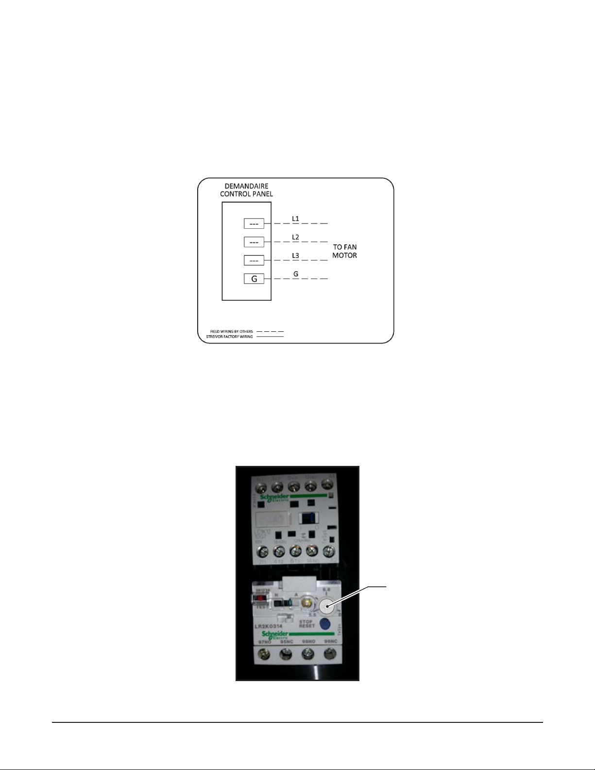
FIGURE 4: Motor Starter (If Provided by Streivor)
Overload Setting (Motor Starters Provided by Streivor)
a. Verify that all power to the control panel is
locked out and tagged out
.
b. Each overload should have been set by the factory to the recommended setting per the table(s) below.
c. Verify that each overload has been set to 125% of the full load amps displayed on the corresponding motor nameplate.
d. The overload setting can be adjusted as needed by rotating the dial to the desired amperage value (Figure 4).
Overload
Setting Dial
FIGURE 3: Motor Circuit Output Power
Motor Circuit Output Power Wiring (Motor Starters Provided by Streivor)
a. Verify that all power to the control panel is
locked out and tagged out
.
b. The output terminals located on the Motor Starter(s) have been pre-wired to the designated output power
terminal
blocks
in the control panel. Connect the output power
terminal blocks
to the designated fan motor(s) as shown on
the DCP drawings (Figure 3).
c. The wires should be torqued to 1.5-1.8 N•m at the
terminal blocks
.
Installation Procedures
8
Streivor DemandAire Bronze Control Panel Installation and Operations Manual
2150 Kitty Hawk Road, Livermore, CA 94551 | (925) 960-9090 | Fax: (925) 960-9055
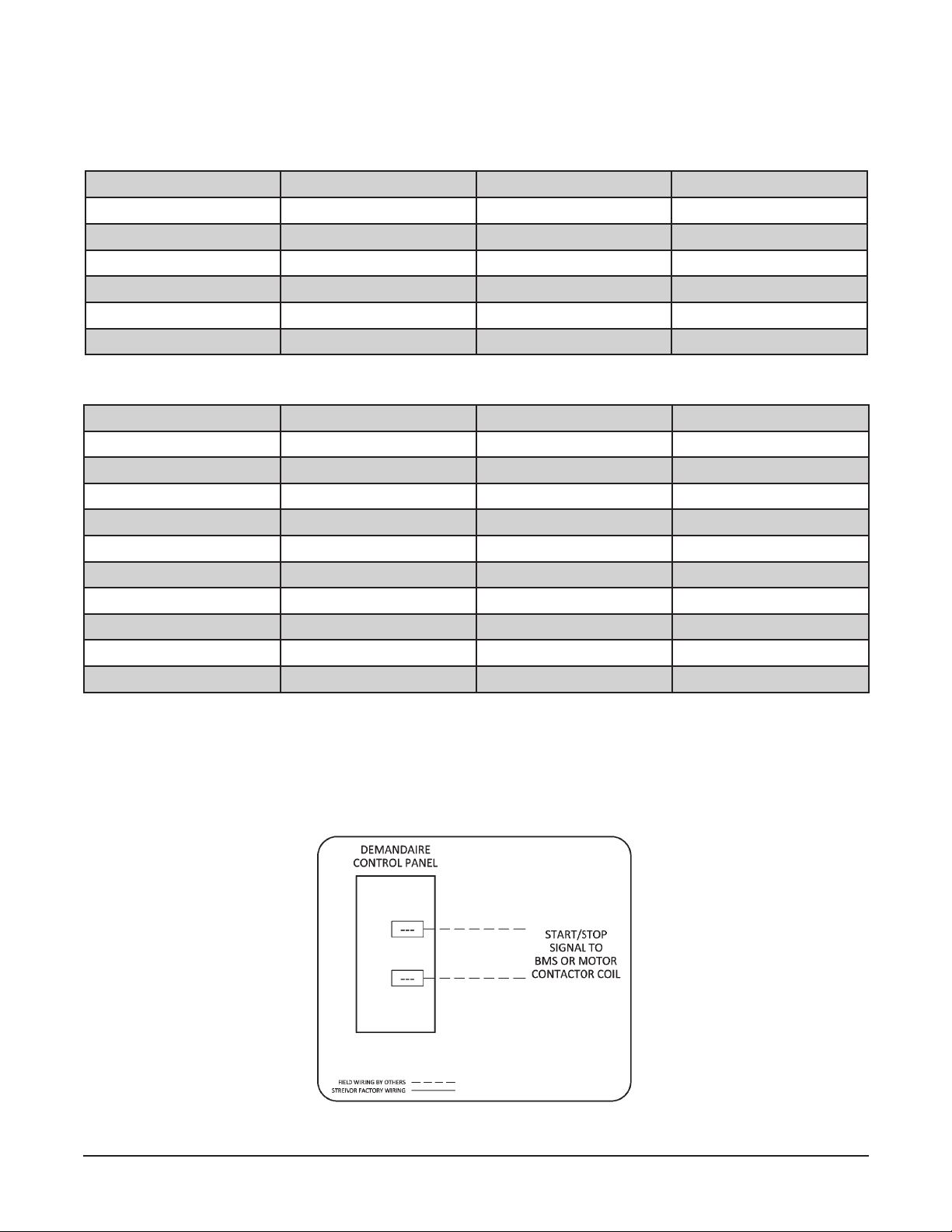
HP 115V 208V 230V
1/6 5.5 3.0 2.8
1/4 7.3 4.0 3.7
1/3 9.0 5.0 4.5
1/2 12.3 6.8 6.1
3/4 17.3 9.5 8.6
1 20.0 11.0 10.0
HP 208V 230V 460V
1/2 3.0 2.8 1.4
3/4 4.4 4.0 2.0
1 5.8 5.3 2.6
1 1/2 8.3 7.5 3.8
2 9.4 8.5 4.3
3 13.3 12.0 6.0
5 20.9 19.0 9.5
7 1/2 30.3 27.5 13.8
10 38.5 35.0 17.5
15 57.8 52.5 26.3
Recommended Motor Overload Settings for Single-Phase Motors
Recommended Motor Overload Settings for Three-Phase Motors
Installation Procedures
Fan Control Signal Wiring (Motor Starters Not Provided by Streivor)
a. Connect the terminal blocks in the control panel designated for the start/stop fan control signals to the appropriate
external destination — Motor Starter(s) (by others) or Building Management System (BMS) (Figure 5).
b. Refer to the DCP drawings for more information on the control signals available (24 VDC, 120 VAC, or Dry Contact).
c. The wires should be torqued to 0.6-0.8 N•m at the terminal blocks.
FIGURE 5: Fan Control Signal Wiring (if Motor Starters Not Provided by Streivor)

9
Streivor DemandAire Bronze Control Panel Installation and Operations Manual
2150 Kitty Hawk Road, Livermore, CA 94551 | (925) 960-9090 | Fax: (925) 960-9055
Installation Procedures
Light Power Circuit Wiring
a. Verify that all power to the control panel is
locked out and tagged out
.
b. Connect 120 VAC single phase power from terminal block 11 (hot), terminal block 12 (neutral), and ground in the
control panel to the wires labeled “Lights” in the junction box on the hood (Figure 6).
c. The wires should be torqued to 0.6-0.8 N•m at the terminal blocks.
FIGURE 6: Light Power Circuit Wiring
Internal Hood Fan (IHF) Power Circuit Wiring for SmartAire Technology Hoods
Per NFPA 96 Section 8.3.2: When its re-extinguishing system discharges, makeup air supplied internally to a
hood shall be shut o.
a. Verify that all power to the control panel is locked out and tagged out.
b.Connect 120 VAC single phase power from terminal block 3(hot), terminal block 4(neutral), and ground in the
control panel to the wires labeled “IHF” in the junction box on each hood (Figure 7).
c. Internal Hood Fan power to terminal blocks 3and 4 will be automatically shunt during a re suppression system
activation to comply with NFPA 96 Section 8.3.2.
d.The wires should be torqued to 0.6-0.8 N•m at the terminal blocks.
FIGURE 7: Internal Hood Fan Power Circuit Wiring

10
Streivor DemandAire Bronze Control Panel Installation and Operations Manual
2150 Kitty Hawk Road, Livermore, CA 94551 | (925) 960-9090 | Fax: (925) 960-9055
FIGURE 8A: Fire Suppression System (FSS) Switch Circuits
Installation Procedures
Terminal Blocks
Allocated for:
Shunt Trip
Building Alarm
{
{
FIGURE 8B: FSS Switch for Building Alarm Circuit
Note: Use FSS
Switch with Lugs
for Building Alarm
Circuit
Fire Suppression System (FSS) Switch Circuit Wiring
a. Verify that all power to the control panel is locked out and tagged out.
b. Locate the FSS switch in the FSS control panel. The FSS switch (also referred to as microswitch) shall have one set
of single-pole-double-throw contacts (Figure 8A).
c. Connect the terminal blocks in the control panel to the FSS Switch(es) (Figure 8A). The building alarm circuit must
be connected to the switch with lugs (Figure 8B).
d. Connect the building alarm circuit to the terminal blocks designated for the building alarm in the DCP (Figure 8A).
e. Refer to the DCP drawings for more detail regarding wiring additional FSS switches.
f. The wires should be torqued to 0.6-0.8 N•m at the terminal blocks.

11
Streivor DemandAire Bronze Control Panel Installation and Operations Manual
2150 Kitty Hawk Road, Livermore, CA 94551 | (925) 960-9090 | Fax: (925) 960-9055
Ambient Resistance Temperature Detector (ARTD) Wiring (Cabinet Mounted)
a. ARTDs that are Control Panel or Cabinet Mounted are pre-wired by the factory. No eld connections are required.
b. Refer to DemandAire drawings to verify ARTD installation location.
Ambient Resistance Temperature Detector (ARTD) Wiring (Remote)
a. Verify that all power to the control panel is
locked out and tagged out
.
b. The ARTD requires a 2x4 J-Box to which it may be directly mounted (Figure 10).
c. Connect the terminal blocks labeled T0-A, T0-B, etc., in the control panel to the ARTD using UL-Listed 22 AWG Three
Strand Shielded Communication Cable (Figure 9). Connect the black lead on the monitor to the red wire leading to
the DemandAire control panel. Connect one of the brown leads on the monitor to the black wire leading to the control
panel and connect the other brown lead on the monitor to the white wire leading to the control panel (Figure 10).
d. The ARTD should be installed in the location shown on the DemandAire drawings or in the kitchen space at least 80’’
above nished oor (A.F.F.), away from direct sunlight, makeup air diusers airstreams, and other sources of heated or
cooled air. The ARTD should be located within 20 ft. of at least one hood controlled by the DemandAire system.
e. The wires should be torqued to 0.6-0.8 N•m at the terminal blocks.
Installation Procedures
FIGURE 10: ARTD Installation Details
Figure 9: ARTD Wiring Connections in DCP
ARTD Shield(s)
Must be Grounded
in the DCP
12
Streivor DemandAire Bronze Control Panel Installation and Operations Manual
2150 Kitty Hawk Road, Livermore, CA 94551 | (925) 960-9090 | Fax: (925) 960-9055
Installation Procedures
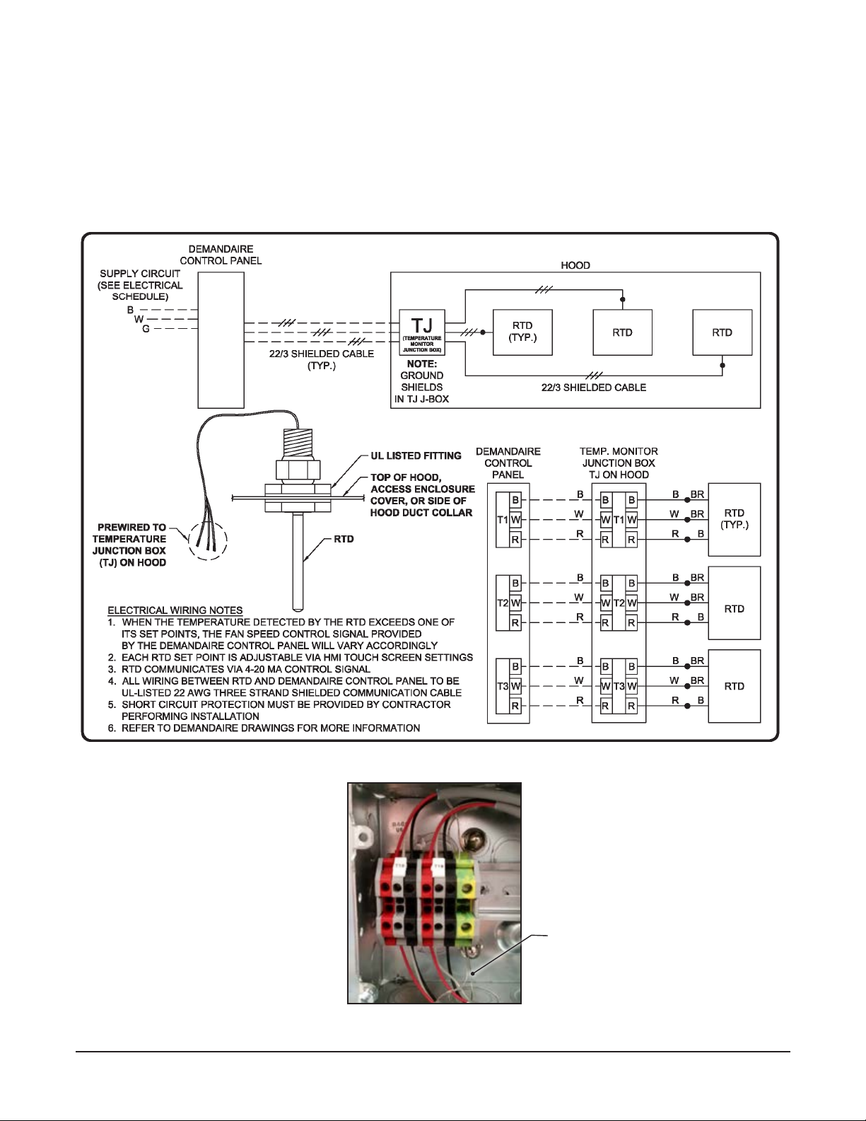
Figure 11: Hood Canopy and/or Duct Collar Resistance Temperature Detector (RTD) Wiring
Hood Canopy and/or Duct Collar Temperature Monitor Wiring
a. Verify that all supply power to the control panel is locked out and tagged out.
b. Connect the terminal blocks labeled T1, T2, T3, etc., in the control panel to the corresponding terminal blocks in
the J-Box on the hood using the UL-Listed 22 AWG Three-Strand Shielded Communication Cable (Figure 11, 12).
c. The wires should be torqued to 0.6-0.8 N•m at the terminal blocks.
Figure 12: Hood Canopy and/or Duct Collar RTD Wiring
Connections in Temperature Monitor Junction Box
RTD Shields Must be
Grounded in Temperature
Monitor Junction
Box TJ on Hood
13
Streivor DemandAire Bronze Control Panel Installation and Operations Manual
2150 Kitty Hawk Road, Livermore, CA 94551 | (925) 960-9090 | Fax: (925) 960-9055
Optional: Modbus TCP Communication Wiring
a. Verify that all supply power to the control panel is locked out and tagged out.
b. A CAT5 or greater Ethernet communication cable may be connected to the RJ45 port on the HMI in the control
panel for Modbus TCP communication with Building Management System(s) (Figure 14).
c. Contact Streivor for Modbus TCP communication points list and associated communication setup parameters.
FIGURE 14: Optional Modbus TCP Communication Wiring
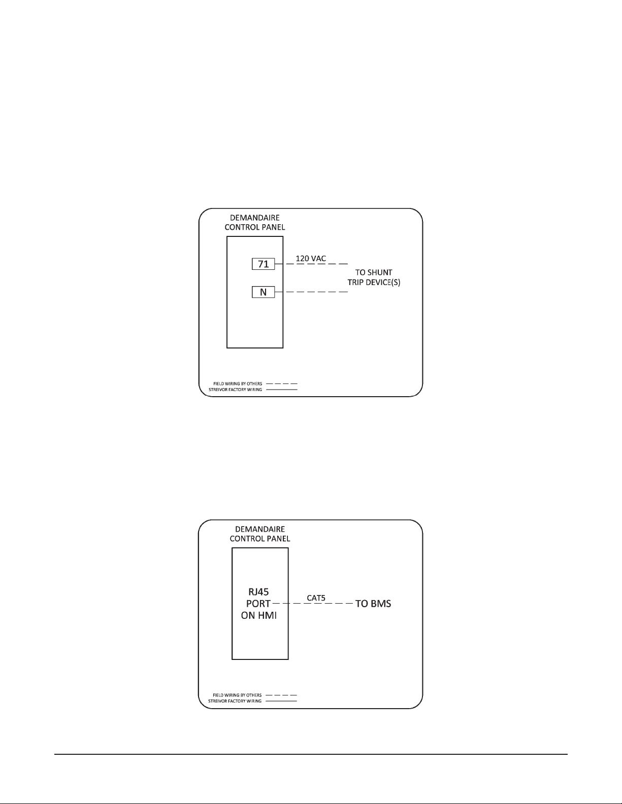
Optional: Shunt Trip Breaker Wiring
Per NFPA 96 Section 10.4.1: Upon activation of any re-extinguishing system for a cooking operation, all sources
of fuel and electrical power that produce heat to all equipment requiring protection by that system and all
electrical outlets located under the exhaust hood shall automatically shut o.
a. Verify that all power to the control panel is locked out and tagged out.
b. Terminal block 71 can be used to provide power to a shunt trip device to comply with NFPA 96 Section 10.4.1.
Terminal block 71 provides 120 VAC power upon re suppression system activation (Figure 13).
c. The wires should be torqued to 0.6-0.8 N•m at the terminal blocks.
FIGURE 13: Optional Shunt Trip Wiring
Installation Procedures

14
Streivor DemandAire Bronze Control Panel Installation and Operations Manual
2150 Kitty Hawk Road, Livermore, CA 94551 | (925) 960-9090 | Fax: (925) 960-9055
Electric Gas Valve Input Power Wiring
a. Verify that all supply power to the control panel is locked out and tagged out.
b. Verify that the circuit breaker amperage is sized correctly for the electric gas valve power circuit per the DCP
drawings.
c. Connect 120 VAC single phase power to the terminal blocks in the control panel labeled H1, N1, and Ground
(Figure 15). Note: The electric gas valve circuit input power is separate from the control circuit input power.
d. The wires should be torqued to 0.6-0.8 N•m at the terminal blocks.
e. Repeat for additional electric gas shuto valve circuits if applicable. Refer to DCP drawings for more information.
Installation Procedures
Electric Gas Valve Output Power Wiring
a. Verify that all supply power to the control panel is locked out and tagged out.
b. Connect 120 VAC single phase power from terminal blocks 130, 131, and ground in the control panel to the
corresponding pre-wired leads on the electric gas valve solenoid(s) (Figure 16).
c. The wires should be torqued to 0.6-0.8 N•m at the terminal blocks.
d. Repeat for additional electric gas shuto valve circuits if applicable. Refer to DCP drawings for more information.
e. Note: A manual keylock bypass switch is pre-wired in the DCP to provide power to the electric gas valve circuit
during commissioning and troubleshooting if necessary.
FIGURE 16: Electric Gas Valve Circuit Output Power Wiring
FIGURE 15: Electric Gas Valve Circuit Input Power Wiring
15
Streivor DemandAire Bronze Control Panel Installation and Operations Manual
2150 Kitty Hawk Road, Livermore, CA 94551 | (925) 960-9090 | Fax: (925) 960-9055
Operation Procedures
Start Up
1. Apply power to the DemandAire Control Panel CONTROL circuit via the appropriate circuit breaker protecting the DCP.
a. Verify that 120 VAC is applied between terminal blocks H and N.
2. If the re suppression system includes an electric gas valve(s), apply power to the GAS VALVE circuit via the
appropriate circuit breaker protecting the electric gas valves.
a. To open the electric gas valve(s) via the HMI touch screen, refer to the Electric Gas Valve Reset Relay section.
3. If the control panel includes motor starter(s), apply power to the MOTOR circuits via the appropriate circuit breakers
protecting the fan motors.
a. Verify that the specied fan motor power is applied to incoming power terminal blocks of each corresponding
motor starter(s).
b. Refer to the DCP drawings for voltage, phase, and designated terminal blocks for each fan motor.
Human Machine Interface (HMI) Touch Screen Control
The HMI touch screen should be installed in a location where it is readily accessible as it contains all of the switches
required to operate the DemandAire system. The HMI also serves as an interface where programming changes are made
to temperature monitor set points. Fan delay settings, fan operation history and current temperature in each hood system
can be viewed on the HMI as well.
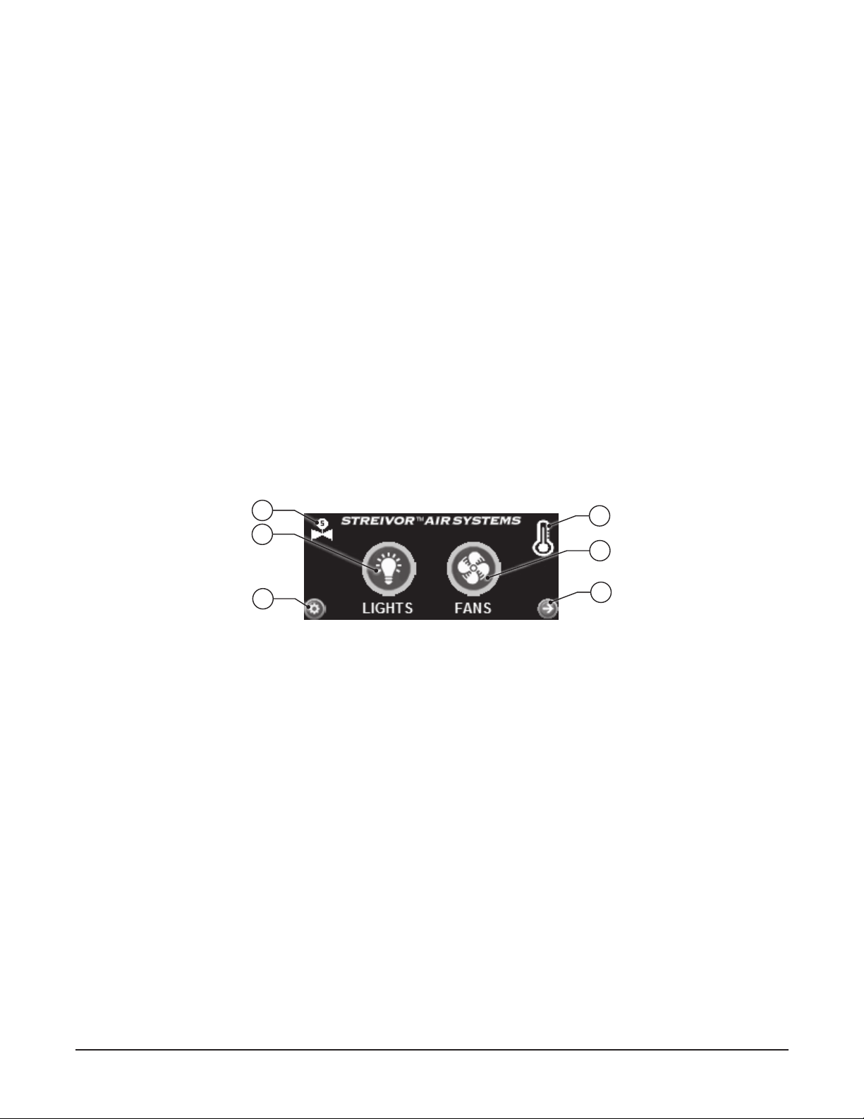
Home Screen
The home screen is the default screen for the HMI which provides the switches required for normal operation of the
DemandAire system.
1. Light Switch
Provides power to the light(s) manually.
2. Fan Switch
Provides power to the fan motor(s) manually.
3. Temperature Indicator
Appears in the top right corner of the home screen when the fans are activated automatically due to an increase in
temperature sensed below the hood(s).
4. Next or Previous Buttons
Allows cycling through each HMI screen.
5. Secure Settings Button
Allows access to password protected system settings. Contact Streivor for help accessing secure settings.
6. Electric Gas Valve Power Indicator
Appears on the top left corner of the home screen when power to the electric gas shuto valve is on.
1
3
2
4
Home Screen
5
6
16
Streivor DemandAire Bronze Control Panel Installation and Operations Manual
2150 Kitty Hawk Road, Livermore, CA 94551 | (925) 960-9090 | Fax: (925) 960-9055
Operation Procedures
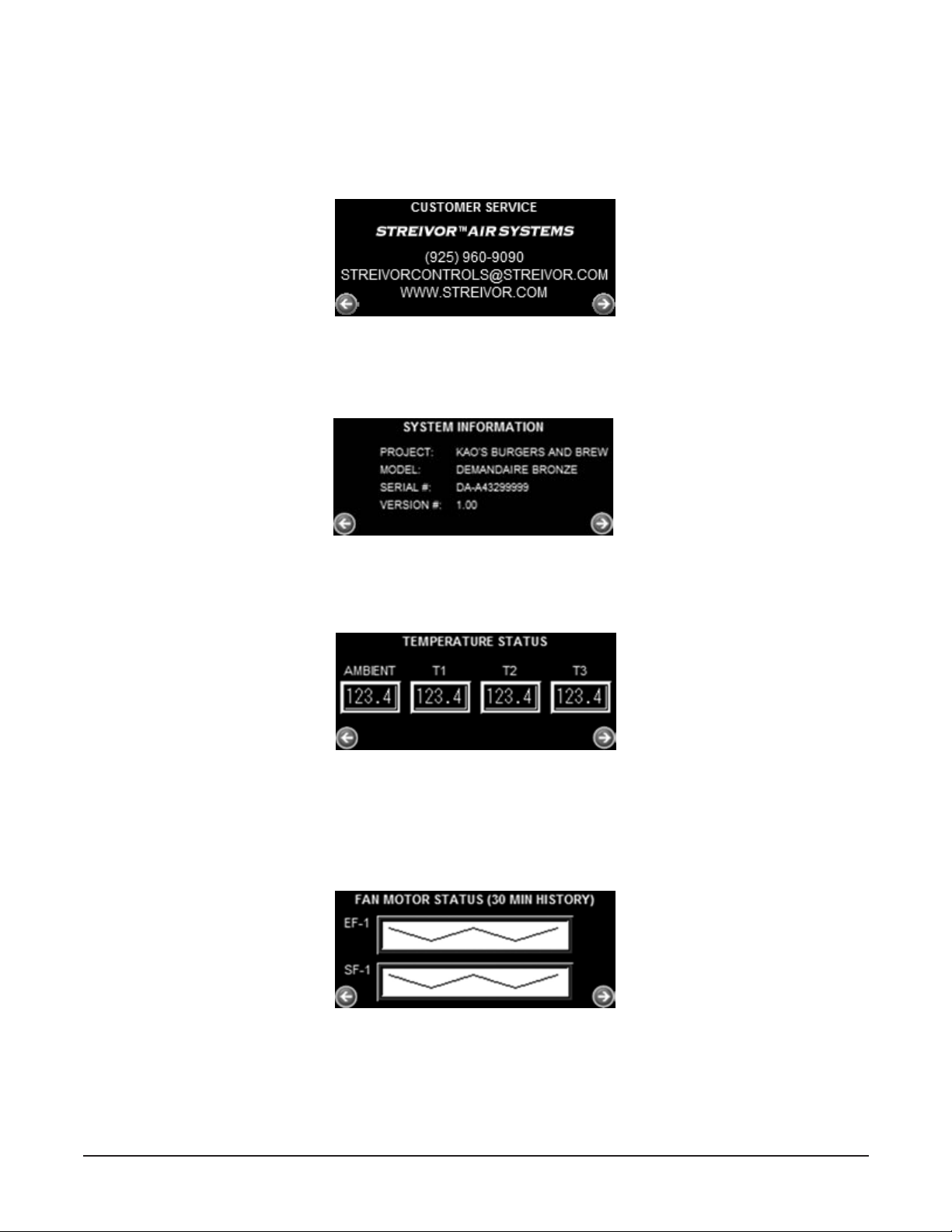
System Information Screen
Customer Service Screen
Temperature Status Screen
Customer Service Screen
Displays Streivor’s company phone number, email address, and website information.
Temperature Status Screen
Displays the current temperature (ºF) readings of the ambient and the hood temperature monitors.
Fan Motor Status Screens
Display the percentage of maximum motor power provided to each fan. 30-minute and 24-hour history graphs are
available.
Fan Motor Status Screen
System Information Screen
Displays the project name, model number, serial number and other pertinent information that indenties this specic
DemandAire system that has been installed.
17
Streivor DemandAire Bronze Control Panel Installation and Operations Manual
2150 Kitty Hawk Road, Livermore, CA 94551 | (925) 960-9090 | Fax: (925) 960-9055
Operation Procedures
NOTE: HOOD(S) WHICH INCLUDE TEMPERATURE MONITOR(S) MAY AUTOMATICALLY PROVIDE POWER
TO THE FAN(S) CONTROLLED BY THE DCP EVEN IF THE FAN SWITCH IS IN THE OFF POSITION.
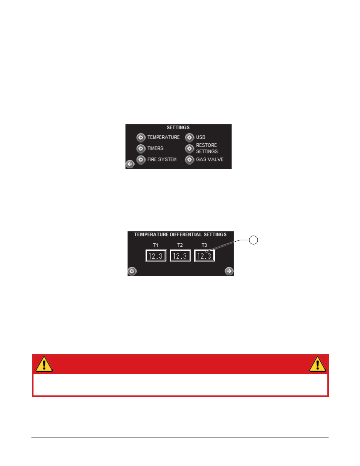
Temperature Dierential Settings Screen
7
Secure Settings (Password Protected)
The DemandAire system provides password protection of secure system settings, such as settings for the
temperature monitors, timers, etc. Only password holders have access to the secure system settings. Adjustments to
secure settings may be necessary due to changes to or around the CKV System and/or the cooking appliances after
initial startup. Consult Streivor for information on accessing or adjusting secure settings.
Settings Screen
Displays access to all secure system settings. Press the settings button next to the settings description, select the
user, and input the password to view and/or adjust the secure settings.
Secure Settings Screen
7. Temperature Monitor Dierential Set Point
Each temperature monitor has an adjustable temperature dierential set point. The set point(s) have been preset by the
factory; however, depending on eld conditions and cooking appliances below the hood, further adjustment may be
necessary in the eld to maintain optimal operation. The recommended temperature dierential set point is approximately
5°F - 15°F above the ambient temperature in the kitchen. WARNING: Consult Streivor prior to modifying temperature
dierential set points. Setting the temperature dierentials too high may result in inadequate exhaust airow
which may result in the loss of capture and containment and/or activation of the re suppression system.
Temperature Dierential Settings Screen (Management)
Displays the temperature monitor dierential settings. The temperature monitor(s) located in each hood are engineered
to automatically turn on the fan(s) controlled by the DemandAire system once the adjustable set point of at least one
temperature monitor has been reached. Temperature dierential set points may be adjusted from the Temperature
Dierential Setting Screen.
18
Streivor DemandAire Bronze Control Panel Installation and Operations Manual
2150 Kitty Hawk Road, Livermore, CA 94551 | (925) 960-9090 | Fax: (925) 960-9055
Operation Procedures
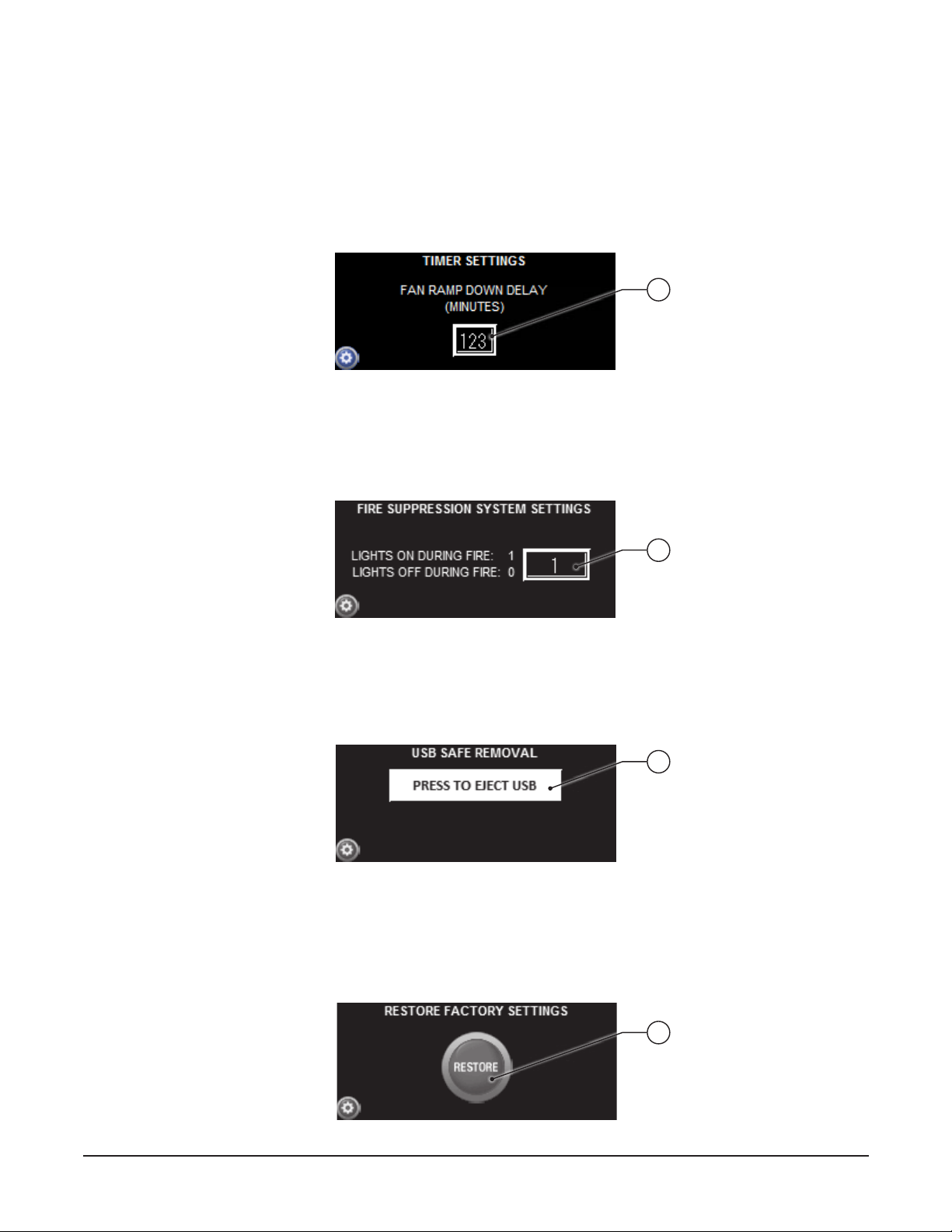
Fire Suppression Systems Settings Screen
Restore Factory Settings Screen
Restore Factory Settings (Management)
11. Restore Factory Settings Button
Restores all settings preset by the factory.
USB Removal Screen
10. USB Safe Removal Button
Allows USB drive to be safely removed from HMI touch screen.
USB Removal Screen
Timer Settings (Management)
8. Fan Ramp Down Delay
Displays the fan ramp down delay time duration which provides power to the fan(s) for a designated time after the
temperature in the hood(s) decreases below the temperature monitor dierential set point.
Fire Suppression System Settings (Management)
9. Lights Operation Settings
Allows the hood lights to remain on (1) or o (0) in the event of a re suppression system actuation.
Timer Settings Screen
8
9
10
11

19
Streivor DemandAire Bronze Control Panel Installation and Operations Manual
2150 Kitty Hawk Road, Livermore, CA 94551 | (925) 960-9090 | Fax: (925) 960-9055
Electric Gas Valve Reset Relay
The electric gas valve power can be reset from the HMI touch screen for DemandAire systems which include an inte-
grated Electric Gas Valve Reset Relay. In the event of a re suppression system actuation, the DemandAire system will
shunt power being provided to the electric gas shuto valve. The valve will close to discontinue the supply of gas to
cooking appliances and will remain in the closed position until manually reset. Contact a certied plumbing technician
to inspect the system following a re suppression system actuation. Upon approval by certied plumbing technician,
proceed to reset power to the electric gas shuto valve.
Following a power outage, the popup screen below will automatically appear over the Home Screen indicating that the
electric gas valve power has been shut o.
Press the arrow button to proceed to reset the electric gas shuto valve(s), following the on-screen instructions until
arriving at the Electric Gas Valve Reset screen below. Press the Reset button to manually reset power to the electric
gas shuto valve. The Electric Gas Valve Reset screen can also be accessed directly from the Secure Settings screen
or through the on-screen instructions following a re suppression system actuation.
After power has been reset to the electric gas shuto valve(s), a conrmation screen will appear and the Electric Gas
Valve Power Indicator will appear in the top left corner of the Home screen.
Operation Procedures
Electric Gas Valve Power O Popup Screen
Electric Gas Valve Reset Screen

20
Streivor DemandAire Bronze Control Panel Installation and Operations Manual
2150 Kitty Hawk Road, Livermore, CA 94551 | (925) 960-9090 | Fax: (925) 960-9055
Operation Procedures
Alarms
The DemandAire Bronze control system provides audible and/or visual indicators on the HMI touch screen in the event
of an alarm condition. Alarms include Temperature Monitor Faults, High Temperature, Fan Motor Overload, and Fire
Suppression System Activation.
Temperature Monitor Alarm
In the event of a temperature monitor alarm, the alarm screen will appear on the HMI indicating which temperature
monitor is not functioning properly. The temperature monitor alarm may occur if the temperature monitor has been
damaged or if it is not wired correctly. The exhaust and supply fan(s) controlled by the DCP will automatically go to full
capacity upon sensing a temperature monitor alarm. Once the alarm has been resolved, press the Reset button to return
to the home screen to resume normal operation.
Temperature Monitor Alarm Screen
High Temperature Alarm
This screen will appear when the temperature below the hood exceeds a predetermined alarm setpoint. If the high
temperature alarm occurs, turn o all cooking appliances below the hood that is activating the alarm and verify that the
exhaust fan is working as specied. Failure to turn o cooking appliances generating heat may result in loss of capture
and containment and/or an actuation of the re suppression system. Contact a qualied HVAC technician to inspect the
exhaust system to determine the reason for the alarm. Once the hood temperature decreases below the high temperature
alarm setpoint, press the Reset button to return to the home screen to resume normal operation.
High Temperature Alarm Screen
Fan Motor Overload Alarm
When motor starters for the fan(s) are provided by Streivor in the DCP, a fan motor overload alarm can occur due to an
overcurrent condition. The fan motor overload alarm will indicate which fan motor overload has tripped. When a fan
motor overload alarm occurs, turn o all cooking appliances and contact a qualied electrician to inspect fan motors and
overloads. Failure to turn o the cooking appliances generating heat may result in loss of capture and containment and/or
an actuation of the re suppression system. Once the fan motor overload has been inspected, resolved and reset, press the
Reset button on the HMI to return to the home screen to resume normal operation.
Fan Motor Overload Alarm Screen
Table of contents
Popular Fan manuals by other brands

IHP
IHP VENT-KIT-6X12 installation instructions

AccuraSEE
AccuraSEE MINI user manual

National Ventilation
National Ventilation monsoon MONS100HT Installation and wiring instructions

Vent-Axia
Vent-Axia 45 40 55B Installation and wiring instructions

Hunter
Hunter Bardot installation manual

Maico
Maico EZF B Series Mounting and operating instructions


