Strong International Ballantyne PRO-35 User manual

Film-Tech
The information contained in this Adobe Acrobat pdf
file is provided at your own risk and good judgment.
These manuals are designed to facilitate the
exchange of information related to cinema
projection and film handling, with no warranties nor
obligations from the authors, for qualified field
service engineers.
If you are not a qualified technician, please make no
adjustments to anything you may read about in these
Adobe manual downloads.
www.film-tech.com

BALLANTYNE PRO-35
35mm Projector Mechanism
Rev. 2/98
STRONG
INTERNATIONAL
a division of Ballantyne of Omaha, Inc.
4350 McKinley Street
Omaha, Nebraska 68112 USA
Tel 402/453-4444 • Fax 402/453-7238

CONTENTS
Preface ....................................................................... 1
Receiving & Installation ............................................ 2
Threading ................................................................... 4
Projection Lens Installation ........................................ 5
Maintenance ............................................................... 6
Operator Adjustments
Pad Rollers ........................................................ 7
Shutter Timing .................................................. 8
Framing Tension ............................................... 9
Intermittent Sprocket Alignment ....................... 9
Intermittent Movement ...................................... 10
Framing Coupler ............................................... 11
Parts Catalog ............................................................. 12

PREFACE
THE PRO-35 is a modern mechanism, streamlined and designed for a long life of unequalled
performance. The projector is designed to meet or exceed standards for film speed, picture stability, and film
protection. Heavy-duty drive components insure reliable operation for extended periods of continuous duty.
THE MAIN FRAME is designed for ruggedness and simplicity. All driving gears are con-
tained within the main frame and submerged in oil. No gears are visible on the drive side of the projector. The
mechanism has been designed with roominess for ease of threading, operation, service, and cleaning. The
projector, designed for long life, carries a one year warranty on the mechanism, including all film-bearing parts.
As a result of the modern design, film-bearing parts can be removed and replaced with great ease.
HIGHEST EFFICIENCY is obtained by the unique conical shutter positioned close to the
aperture for maximum light efficiency. Aperture plates are easily replaced for any screen ratio. The lens holder
is designed to accept a four-inch lens, and reducers are supplied to accommodate 2-25/32 inch (72mm) lenses.
The lens barrel allows complete prefocusing facilities. The lens mount is of heavy, cast iron construction to add
weight and bulk for positive anchorage and elimination of any fragility. The lens carrier is mounted to its base
with a double V lens slide with a microthread lens focus adjustment. A unique picture changeover system is
a built-in part of the projector.
THE INTERMITTENT MOVEMENT is of heavy construction with a large cam and star.
The starwheel is webbed for additional strength. Unlike commonly used drives, the fractional-horsepower
motor drives the intermittent, which in turn drives the projector and soundhead. Framing is accomplished by
moving the intermittent sprocket, independent of the shutter, by means of a Delrin spiral coupling. With this
method. no other compensation is needed when the picture is framed, and shutter adjustment controls are not
necessary.
THE FILM GATE AND TRAP are unique. They are made as an assembly and can be re-
moved as a single unit, thereby eliminating the repeated adjustments required to keep the gate aligned with the
trap. Although the film gate is a part of the trap assembly, the gate pressure pads is easily removed for cleaning
by means of one screw. The film shoes on the gate pressure pad can be adjusted for tension while film is in
motion. The opening and closing mechanism for the film gate incorporates a cam adjustment, allowing adjust-
ment of the gate and trap spacing while the machine is running.
AN OIL DRAIN is easily accessible on the front of the projector main frame to permit draining
the projector oil as a service routine. The oil level is indicated by a ring on the clear oil fill tube visible from the
off-operator side of the mechanism. A can of Ballantyne Projector Oil is supplied with the projector; use only
genuine Ballantyne Projector Oil (Part No. 21-98126) in the mechanism.
IN ORDER that all the many features of the Pro-35 may be fully realized, it is recommended
that the following instructions be studied carefully to acquaint the operator thoroughly with the mechanism.
IF AT ANY TIME you have a question, or desire aid in securing anticipated results, write
directly to STRONG INTERNATIONAL, 4350 McKinley Street, Omaha, Nebraska 68112.
1

RECEIVING & INSTALLATION
THE PRO-35 PROJECTOR is shipped in a sturdy wooden crate to minimize the possibility of
damage in shipment. Remove first the top of the crate (as marked). Identify the operators side of the projector
and remove that side of the crate. The projector is secured to the crate with (2) 3/8-16 screws threaded into the
projector base casting, and (2) 3/8-16 bolts with hex nuts. Remove all (4) of these fasteners. Inspect the
projector and report any damage to the freight carrier immediately. It is the responsibility of the consignee, not
the shipper, to initiate damage claims.
IF INSTALLING a Pro-35 to a VIP Base, the Model VII soundhead is factory-mounted to the
base; otherwise, the soundhead must be mounted to a pedestal or projection console. Three holes, on the top
surface of the Model VII main frame casting are tapped 3/8-16 and align with (3) clearance holes in the bottom
casting of the Pro-35. Mount the projector to the soundhead and secure using the (3) 3/8-16 socket head screws
provided. The locations of these clearance holes are held to a close tolerance, and no further projector-to-
soundhead alignment is required.
INSTALL THE INTERMITTENT
FLYWHEEL and pulley assembly to the intermittent cam-
shaft as illustrated. Observe the assembly sequence of
the components. Do not add oil to the projector until
first installing and securing the intermittent flywheel.
INSERT THE PLASTIC FUNNEL into
the oil fill cup on the top of the projector and add Ballantyne
Projector Oil until the oil level reaches the ring on the oil
fill hose. While adding the oil, periodically rotate the in-
termittent flywheel to turn the mechanism and eliminate
air locks. DO NOT OVERFILL.
AN ALTERNATE METHOD of adding
the projector oil is to remove the breather tube from the
top of the projector and prop open the oil fill cup. Insert
the funnel into the breather tube opening and add the oil,
while periodically rotating the intermittent flywheel as
above. After filling, replace the breather tube and reset
the lid of the oil cup.
INSTALL THE DRIVE BELT between the motor pulley and the intermittnet flywheel pulley.
The standard 115 V.AC induction motor is mounted to the base casting of the projector in a pivoting support
cradle. Apply belt tension by tightening the front-mounted socket head screw connected to the motor cradle
until belt tension is adequate.
THE SYNCHRONOUS DRIVE MOTOR mounts to the top casting of the projector. Run the
drive belt from the motor pulley to the intermittent flywheel pulley and apply belt tension by tighening the idler
roller mounted to the inside of the top casting against the drive belt.
3041 Screw
2783 Cap
2786-D Washer
Intermittent Movement
P8014 Flywheel & Pulley
Oil Level Ring
(Do Not Overfill)
2943 Oil Fill Hose
2
INSTALLATION (continued)
INSTALL THE SOUNDHEAD DRIVE BELT as
illustrated. Slide the 54-67-0 idler pulley assembly against
the belt to set the belt tension. Securely tighten the (2) socket
head screws when belt tension is correct.
DO NOT OVERTIGHTEN either of the drive belts.
Timing belt tension should be sufficient to allow the belt cogs
to firmly engage the pulley teeth. Tighening beyond this point
shortens belt life and may damage shafts and bearings.
CONNECT THE AC INPUT to the motor termi-
nals. See the Data Plate on the motor to determine the correct
voltage requirements. The motor line must be externally
switched; no motor switch is provided with the Pro-35. Ap-
ply a second (unswitched) AC line to the Framing Lamp Power
Supply/ Changeover Power Supply.
2812 Pulley
(on Pro-35)
54-67-0 Idler
2937 Timing Belt
2829 Pulley
(on Model VII)
3

THREADING
THREADING THE PROJECTOR correctly is one of the operators most important duties.
Proper attention to detail in this operation pays off in improved performances and long print life.
IT IS RECOMMENDED to clean all film-bearing surfaces prior to each threading operation.
The roomy interior of the Pro-35 simplifies this procedure. Open the film gate using the Gate Release Lever.
Loosen, but do not remove, the Pressure Pad Retaining Screw, and dismount the gate pressure pad assembly.
Wipe the gate pads and the trap shoes using a clean, dry cloth. Re-install the gate pressure pad assembly.
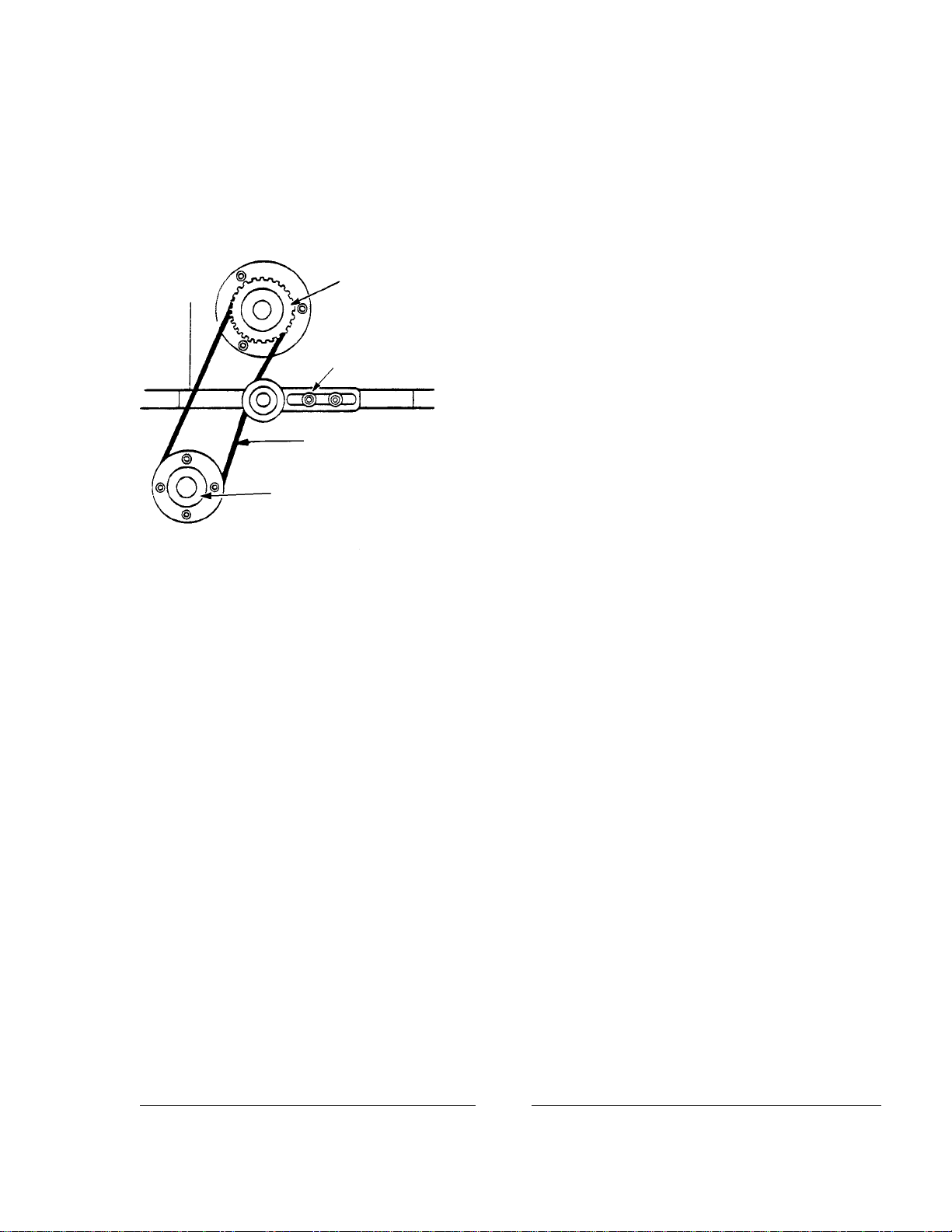
THREAD THE PROJECTOR following the film path illustrated above. Check for correct
frame position at the Framing Aperture before closing the gate and engaging the intermittent sprocket shoes.
After closing the gate, make certain that the gate pressure pad (Item A) is inside the lateral stabilizer plate (Item
B). The lateral stabilizer should be resting on the outboard edge of the film.
INCH THE PROJECTOR by hand and carefully inspect the film path before turning on the
projector motor. Run fingers over each sprocket to insure that the sprocket teeth are centered in the film
perforations, and the film is centered between the pad roller flanges. Check again the position of the film in
the framing aperture. A correct frame image in the framing aperture insures correct frame positioning on the
picture aperture.
MISFRAMES can be corrected by rotating the Framing Lever up or down. This adjustment
may be made when the projector is running.
Framing Aperture
FILM PATH
Pressure Pad
Retaining Screw
Film Gate
Release Lever
Framing Lever
4

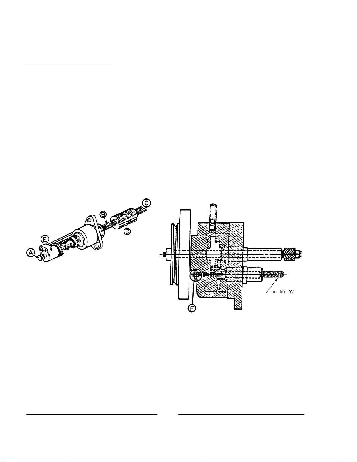
PROJECTION LENS INSTALLATION
1. Adjust Focus Knob (E) to the center of its travel. The degree of torque required to operate the focus
adjustment is controlled by tightening or loosening socket head screw (H). NOTE: too loose a setting may
allow focus drift.
2. Insert Lens Reducer (A) into Lens Barrel (C) with Pin (B) seated in notch as shown. Secure the Lens
Reducer by tightening Knob (D).
3. Install Projection Lens (F) into Lens Reducer and adjust for correct focus. When installing an anamorphic
lens and adapter, observe proper horizontal anamorphic correction in addition to focus.
4. When the picture is correctly focused and positioned, lock the lens to the lens reducer by tightening the (2)
nylon set screws through access holes (G).
5. With the lens mated to the reducer in this manner, little or no adjustment of focus control knob (E) will be
required when changing projection format, i.e. CinemaScope to wide-screen (anamorphic to flat).
5

MAINTENANCE
CLEANLINESS is the most important element in maintaining the Pro-35 projector. It is advis-
able to thoroughly clean all film-bearing surfaces in the gate and trap, each sprocket, and all pad rollers prior to
every performance.
USE A CLEAN, DRY CLOTH to clean the inner surfaces of the gate pressure pads, trap
shoes, and studio guides. A toothbrush with soft to medium bristles is an excellent tool for cleaning sprocket
teeth and pad rollers. Pad rollers must operate freely at all times; if unable to rotate, they will rapidly develop
flat spots and require replacement.
THE LATERAL STABILIZER in the film
trap must be removed and cleaned periodically. Remove
the shoulder screw (A), coil spring (B), and stabilizer plate
(C) as shown. Make certain area (D) is free of dirt and film
debris. After replacing, make certain stabilizer plate (C)
acts freely against spring (B).
THIS STABILIZER ASSEMBLY must be
removed to gain access to the trap mounting screw in area
(D). This captive, slot-headed screw must be loosened to
permit dismounting the trap for cleaning or service.
CHANGE THE OIL at least once every year of normal service. Remove the hex head screw
from the end of the drain pipe and allow the old oil to drain. Inspect the O-ring below the head of the drain screw
and replace if cracked or worn. Replace the drain screw and fill the projector with Ballantyne Projector Oil
(Part No. 21-98126). Fill to the ring only; do not overfill.
CHECK THE DRIVE BELTS and adjust for proper tension if required. Inspect the belts and
replace if cracked or worn.
PERIODICALLY INSPECT the entire mechanism and make certain all fasteners are securely
tightened. Vibration from normal operation may cause fasteners to loosen after prolonged periods.
6

OPERATOR ADJUSTMENTS
THE FINE ADJUSTMENTS necessary to project the steadiest picture are made at the factory
by skilled technicians prior to shipping. In time, these adjustments will change, and require the attention of the
operator. Because of the advanced design of the Pro-35, these periodic asjustments can be made in a short time
with a minimum of effort.
PAD ROLLER ASSEMBLIES
1. Place the pad roller assembly in the CLOSED position. Loosen set screw (A).
2. Loosen set screw (B) on the rear eccentric roller (C). Rotate pad roller (C) away from film sprocket (D).
3. Wrap TWO ticknesses of film around film sprocket (D). This spacing will permit the safe passage of film
splices.
4. Position pad roller (E) so that it just touches the two thicknesses of film on film sprocket (D).
5. Tighten set screw (A).
6. Rotate the eccentric pad roller (C) so that it too just touches the film on sprocket (D).
7. Tighten set screw (C).
Lower (Holdback)
Sprocket Assembly
Pad Roller, Closed (Open) Upper (Feed)
Sprocket Assembly
Pad Roller, Closed (Pad Roller,
Open)
FILM GATE ASSEMBLY
Coarse adjustment of gate pressure pad tension is made at point
(D). Adjust Ecccentric Screw (D) while the machine is running. At the
minimum setting, film transport noise will be excessive. Adjust the gate
toward the trap until transport noise minimizes. Observe the projected pic-
ture on the screen.
Fine tension adjustments are made at points (A), (B), and (C).
Observe the screen while making fine adjustments; maintain the lightest
possible gate tension without affecting the quality of the picture.
The large (1/4-20) set screws at point (E) permit adjusting the ver-
tical position of the film gate. Keep the gate pressure pads parallel with the
trap studio guides. The small set screws at point (E) lock the settings of the
1/4-20 set screws.
7

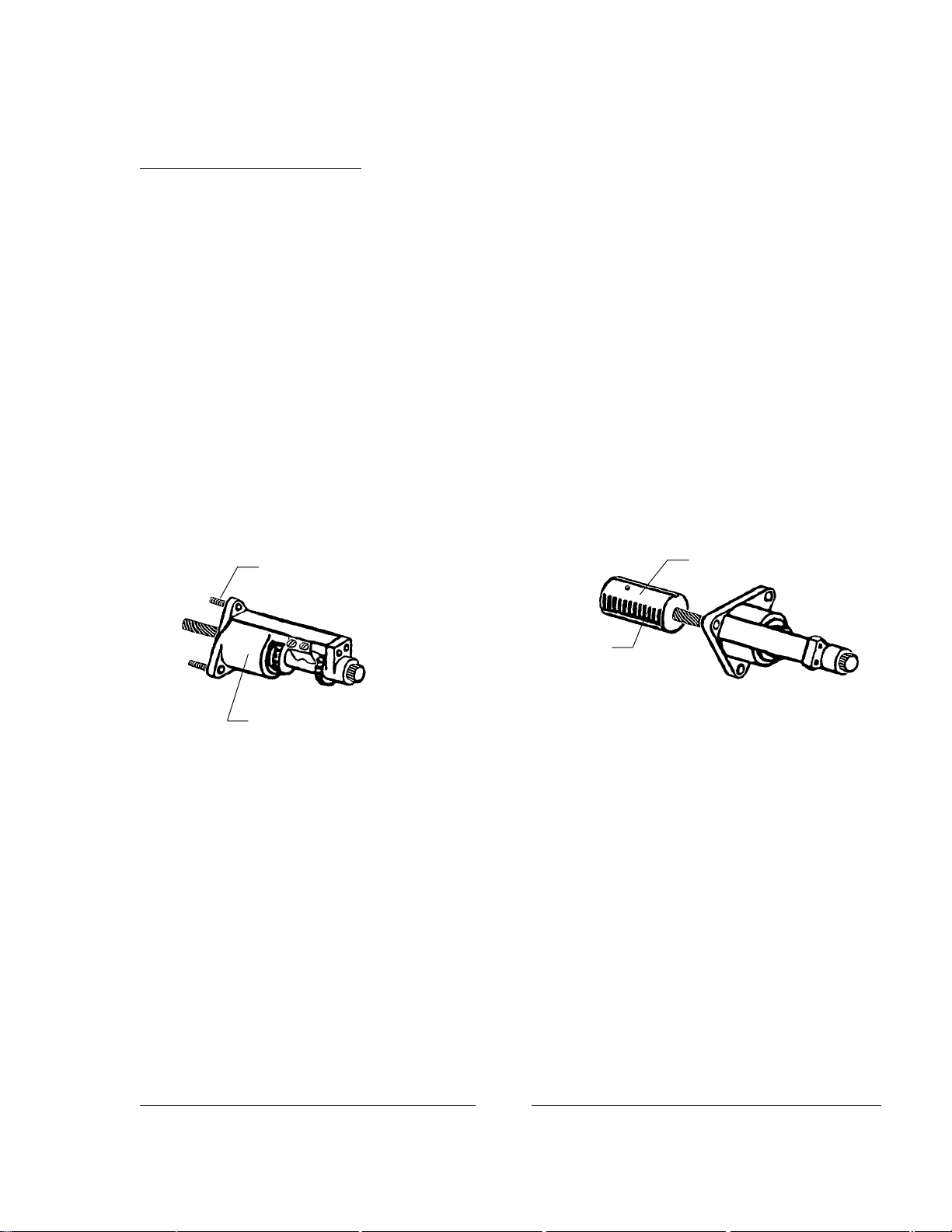
SHUTTER TIMING
A mis-timed shutter will cause noticeable flicker or ghosting of the projected picture. Travel Ghost is
the term commomly applied to vertical streaking of lighter areas against a darker area, and is particularly
apparent during opening or closing titles and credits.
To gain access to the shutter, remove the framing lever and rear quarter panel as shown:
Framing Lever
Quarter Panel
1. Loosen screw (A) to permit the shutter blade to rotate freely on its shaft.
2. Turn inching knob (B) to cycle the intermittnet movement. With the movement at rest, select one intermit-
tent sprocket tooth (C) and mark its position with a stationary object, like the tip of a screwdriver blade.
3. With the sprocket tooth position marked, turn inching knob (B) slowly in a counterclockwise direction until
the intermittent sprocket (C) advances TWO teeth.
4. Hold the inching knob (B) to prevent the mechanism from moving, and rotate the loosened shutter blade
until one of the blades is fully blocking the picture aperture. The center of the blade should align with the
aperture centerline (D).
5. Firmly tighen screw (A). Repeat Step 3. After a (2) tooth advance, the center of the shutter blade should
be at the aperture centerline (D) as shown.
6. Replace the quarter panel and the framing lever.
8

FRAMING TENSION
The amount of tension required to operate the framing lever (I) is adjustable, although a degree of
tension is required to prevent the film from creeping out of frame. The adjustment screw (B), held in position
by locknut (A), applies or relieves tension on the nylon tension plug (C). In turn, the tension plug (C) applies or
relieves pressure against the vertical framing shaft (D), regulating the coupler assembly (E). Torque applied to
framing lever (I) is transmitted through shaft (H) and gear (G). Rotation of the vertical framing shaft (D) moves
the coupler assembly on a horizontal plane, changing the frame position of the intermittent sprocket (F).
Framing tension is adjusted as follows:
1. Remove the framing lever and the rear quarter panel (see
Shutter Timing).
2. Remount the framing lever (I).
3. Loosen locknut (A) and tighten or loosen adjustment screw
(B) as required.The framing lever (I) should move with
relative ease, however, inadequate pressure on tension
plug (C) will allow film to creep out of frame.
4. Re-tighten locknut (A); remove framing lever (I).
5. Replace the rear quarter panel and the framing lever.
INTERMITTENT SPROCKET ALIGNMENT
The intermittent sprocket is secured to the outboard
intermittent sprocket shaft in a manner which permits a slight
degree of horizontal adjustment of the sprocket. This adjust-
ment is facilitated by use of a Studio Guide Gauge available
from Strong International Dealers. Gauge 3567-F (as shown)
is designed for Pro-35 projectors in current production; for
older models (without the lateral stabilizer plate), order Gauge
3568-F.
Place the gauge between the studio guides (A) as
shown. Loosen, but do not remove, screw (C). Slide the
sprocket on its shaft until it is centered on the narrow portion
of the gauge. Securely re-tighten screw (C).
NOTE:
3567-F = 1.377 in. wide
3568-F = 1.375 in. wide
9
INTERMITTENT MOVEMENT
The intermittent movement is the mechanical heart of the Pro-35. Components are machined to near-
zero tolerances, and assembly, run-in, and testing are performed by trained personnel using special tools and
fixtures. For this reason, operator adjustments performed in the field are very limited.
Factory Rebuilt intermittent movements are available under a Repair/Exchange program. Contact an
authorized Strong International Dealer for details; do not return Pro-35 intermittent movements to the factory
without first acquiring a Return Authorization Number.
The outboard bearing assembly is accessible at the end of the intermittent sprocket shaft on the thread-
ing side of the projector. The purpose of the outboard bearing adjustment bolt (A) is to keep the ends of the
intermittent sprocket shaft (B) in contact with starwheel shaft (C), eliminating any end play at the intermittent
sprocket. Adjustment bolt (A) is the only field-adjustable element.
Adjust bolt (A) fingertight only. Correctly set, bolt (A) will keep shaft (B) in contact with shaft (C)
without end play or binding. DO NOT USE PLIERS OR ANY OTHER FASTENING TOOL.
NOTE: Possibly because of its accessibility, operators sometimes overtighten bolt (A). This action
causes DAMAGE in the bearing area (E) and applies stress on the starwheel bushing area (C) and coupling (D).
Excessive tension for prolonged periods may damage the ENTIRE MOVEMENT.
On the drive (off-operator) side of the mechanism, beneath the intermittent flywheel, the cam stop pin
and locknut assembly (F) is accessible. This assembly is considered field-adjustable only when the adjustment
is performed by QUALIFIED PERSONNEL. Consult the factory before attempting to change the setting of the
cam stop pin.
10
INTERMITTENT COUPLING
The intermittent coupling is not an integral part of the intermittent movement, and can be readily
removed for repair, service, or replacement.
1. Drain the oil from the projector.
2. Remove the framing lever and the rear quarter panel (see Shutter Timing).
3. Replace the framing lever.
4. Remove the film gate and the lateral stabilizer plate (from the trap).
5. Loosen the trap mounting screw (exposed by removing the lateral stabilizer) and dismount the trap. The
trap is located on (2) dowel pins, and requires reasonable force to unseat. DO NOT strike the intermittent
sprocket teeth when removing the film trap.
6. Loosen the locknut and framing tension screw on the back of the main frame by 1/4 turn.
7. Remove the (3) socket head screws securing the intermittent sprocket assembly to the main frame. Rotate
the framing lever while drawing the sprocket assembly out of the mechanism.
8. The coupler assembly may come out with the intermittent sprocket assembly. If not, rotate the framing
lever to move the coupling forward, and remove by hand.
9. Take carefult notice of the end of the coupler assembly and replace it onto the shaft exactly as it came off.
Repeat this several times to observe the feel of the fit.
10. Replace the coupling on the sprocket shaft and align the rack teeth vertically as illustrated. Slide the
coupling and the sprocket shaft assembly into the main frame with the rack teeth facing the shutter. Rotate
the sprocket back and forth to align the coupling splines to the starwheel shaft splines. When correctly
installed, it will fit on the shaft with the same feel as before.
11. Replace all parts and hardware removed prior.
12. Tighten the framing tension adjustment screw to apply correct pressure on the framing assembly. Tighten
the locknut.
13. Secure the drain plug screw and replace the projector oil.
Mounting Screw,
(1) of (3)
Rack Teeth
Coupling Assembly
Intermittent Sprocket Assembly
11


Pro-35 Parts Catalog
Ballantyne replacement parts are available through any
authorized Strong International Dealer.
Please order by
Part Number
and
Description.
All returned goods must display a Return Authorization
Number issued to an authorized Strong International
Dealer.
STRONG INTERNATIONAL
a division of Ballantyne of Omaha, Inc,
4350 McKinley Street
Omaha, Nebraska 68112 U.S.A.
Tel 402/453-4444 • Fax 402/453-7238
2749 2651
2973 2727
2920
2921
2752N
2922
2751
2752-S
2650
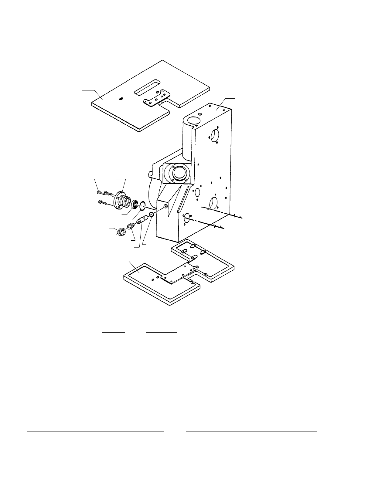
Part No. Description
2650 Base Casting
2651 Main Frame
2727 Framing Shaft Cap, Rear
2749 Top Plate Casting
2751 Tension Plug, Nylon
2752-S Tension Adjusting Screw
2752N Lock Nut
2920 Ball Bearing
2921 O-Ring
2922 O-Ring
2973 Screw, 10-32 x 5/8" Socket Head
MAIN FRAME
(toGuideRollerAssembly26-15-0)
(toFramingAssembly23-60-0)
13
Part No. Description
2651 Main Frame
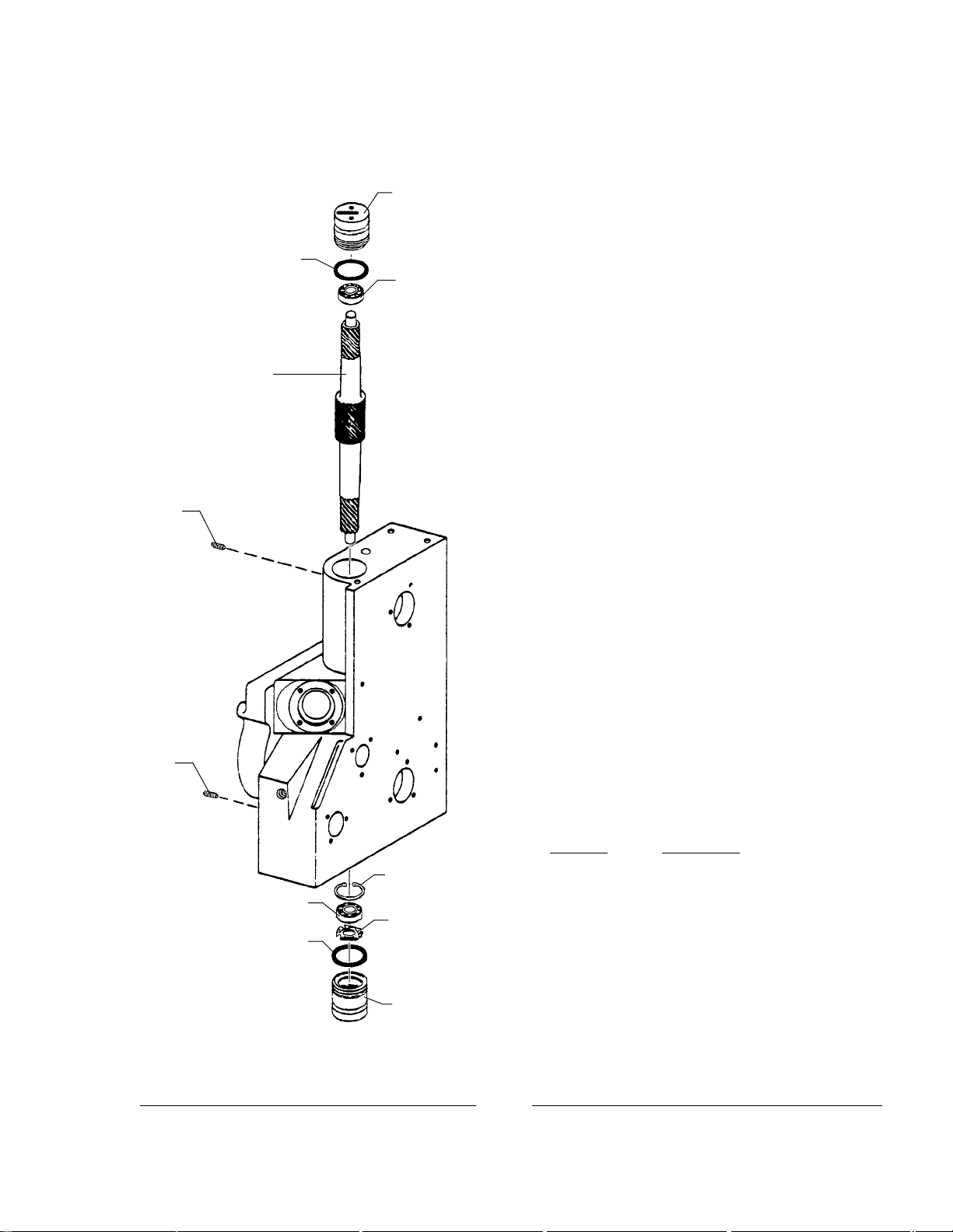
2716 Vertical Shaft
2744 Top Cap
2745 Bottom Cap
2815 Cap Locking Screw (2 reqd.)
2900 O-Ring (2 reqd.)
2901 Ball Bearing (2 reqd.)
2902 Snap Ring (Early Models)
(2902 not used in Current Production)
2903 Spring Washer
VERTICAL SHAFT ASSEMBLY
2902
(Early Models)
2901 2903
2900
2745
2815
2815
2716
2744
2901
2900
14

Part No. Description
2651 Main Frame
2665R-1 Horizontal Shaft & Pad Roller Housing, Upper
2712 Horizontal Shaft Cap, Rear (2 reqd.)
2715 Horizontal Sprocket Shaft (2 reqd.)
2717 Helical Gear, Horizontal Shaft (2 reqd.)
2812 Drive Sprocket, Model VII Soundhead
2835 Horizontal Shaft & Pad Roller Housing, Lower
2900 O-Ring (2 reqd.)
2901 Ball Bearing (2 reqd.)
2904 O-Ring (2 reqd.)
2905 Ball Bearing (2 reqd,)
2906 Film Sprocket, 35mm VKF®(41GL37B)
2951 Oil Seal (before Serial Number 2448)
2952 Oil Seal
2968 Set Screw, 1/4-20 x 1/2"
2972 Screw, 10-32 x 1/2" Socket Head
2973 Screw, 10-32 x 5/8" Socket Head
3052 Set Screw, 1/4-20 x 3/8"
4397 Oil Seal (after Serial Number 2448)
P8114 Film Stripper Assembly (not shown)
HORIZONTAL SHAFT ASSEMBLIES
2952
2972
2712
2904
2905
2715
2717
2651
2968
2812
2952
2972
2712
2904
2905
2717
2715
2901
2900
3052
(toP8114)
2665R-1
2951/4397
2973 2906
2901
2900
2835
2951/4397
2973
2906
(toP8114)
3052
15

Part No. Description
21-42-51R2 Shutter Shaft Assembly
28-65-3 Solenoid & Bracket Assembly
2651 Main Frame
2720-A Shutter Shaft Housing, Outer
2720-B Shutter Shaft Housing, Inner
2754-R 2 Shutter Shaft
2763 Gasket
2765R-1 Douser Blade
2768D Gear, Shutter Shaft
2783 Shaft Cap
2786 Cap Washer, Brass
2800 Shutter Blade
2801 Connecting Link
SHUTTER SHAFT ASSEMBLY
P-1432
3001
2803 2651
28-65-3
2804
2805
21-42-51R2 Assembly
2720-A
2720-B 2763 4397
2901
2915-S
29152754-R2
10181
10181 4482
2768D 4481
3041
2783
2917
2801
2800
2918
2765R-1
2967
2802-C
2786
3006
2922
2847
3008
41-51111
2913
2912 3261
3066
2971
H-3328
41-51606
28-63-3
Assembly
16
Table of contents


