Stryker 1488 User manual

1488 HD Video Camera
Volume l of ll
1488010000
1488010001
1488210105
1488610122
1488710105
English
Français
Deutsch
Italiano
Português
Español
Nederlands
Dansk


Contents
English.............................................................EN-1
Français ...........................................................FR-45
Deutsch............................................................DE-95
Italiano ............................................................IT-145
Português........................................................PTC-193
Español............................................................ES-245
Nederlands......................................................NL-295
Dansk...............................................................DA-347


EN-1
Contents
Warnings and Cautions..................................................EN-3
Product Description and Intended Use ........................EN-5
Indications/Contraindications .....................................................................EN-6
The Camera Console........................................................................................EN-7
The Camera Head.............................................................................................EN-9
The C-Mount Coupler................................................................................... EN-10
Setup and Interconnection......................................... EN-11
Setting Up the Console .............................................................................. EN-12
Setting Up the Camera Head..................................................................... EN-14
Setting Up the Coupler................................................................................ EN-14
Connecting the DVI Fiber Outputs.......................................................... EN-16
Operation ..................................................................... EN-17
Operating the Camera with a Light Source.......................................... EN-17
Powering the Console On/O................................................................... EN-18
Controlling Remote Video Accessories.................................................. EN-18
Using the Camera Head Buttons.............................................................. EN-19
Using the Touchscreen Interface.............................................................. EN-20
Performing the White-Balance Test......................................................... EN-22
Advanced Features........................................................................................ EN-22
Troubleshooting.......................................................... EN-23
Reprocessing................................................................ EN-27
Cleaning the Console................................................................................... EN-27
Cleaning, Disinfecting, and Sterilizing the Camera Head ............... EN-27
User Maintenance........................................................ EN-36
Using Sterile Drapes ..................................................................................... EN-36
Replacing the Fuses...................................................................................... EN-36
Periodic Maintenance Schedule............................................................... EN-36
Disposal............................................................................................................. EN-36
Technical Specications.............................................. EN-37
Electromagnetic Compatibility................................................................. EN-39
Symbol Denitions...................................................... EN-43


EN-3
Warnings and Cautions
Please read this manual and follow its instructions carefully. The words
warning, caution, and note carry special meaning and should be carefully
reviewed:
Warning Indicates risks to the safety of the patient or user. Failure to
follow warnings may result in injury to the patient or user.
Caution Indicates risks to the equipment. Failure to follow cautions
may result in product damage.
Note: Claries the instructions or presents additional useful information.
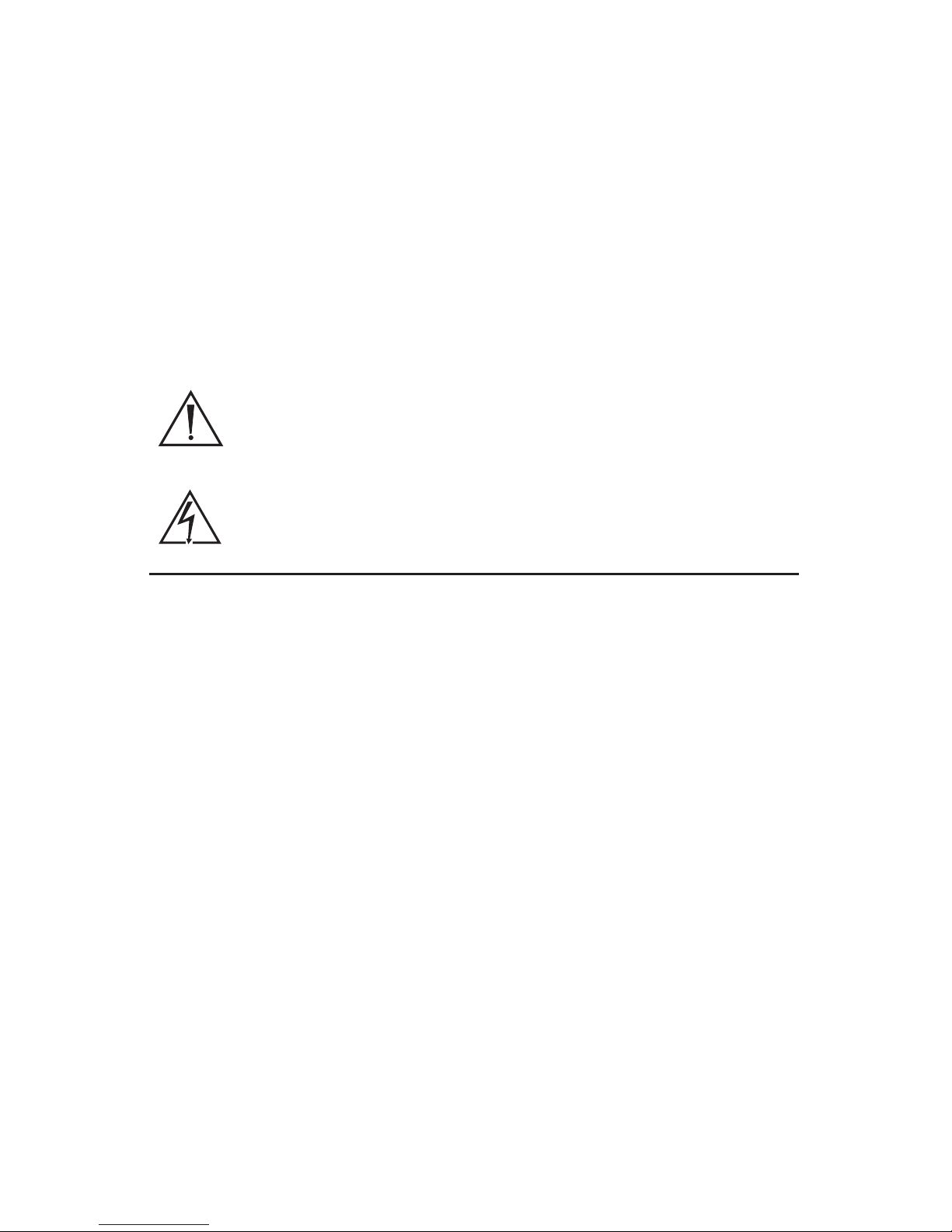
An exclamation mark within a triangle is intended to alert the
user to the presence of important operating and maintenance
instructions in the manual.
A lightning bolt within a triangle is intended to warn of the
presence of hazardous voltage. Refer all service to authorized
personnel.
IMPORTANT SAFETY NOTICE: Before operating this device, please read this
operating manual thoroughly and carefully. When using this device with
a light source, re and/or severe injury may result to the patient, user, or
inanimate objects if the instructions in this manual are not followed.
All light sources can generate signicant amounts of heat (exceeding
41°C/106°F) at the scope tip, the scope light post, the light cable tip, and/or
near the light cable adapter. Higher levels of brightness from the light source
result in higher levels of heat. Always adjust the brightness level of the camera
and the monitor before adjusting the brightness level of the light source.
Adjust the brightness level of the light source to the minimum brightness
necessary to adequately illuminate the surgical site.
In addition, adjust the internal shutter of the camera higher in order to run
the light source at a lower intensity. Avoid touching the scope tip or the light
cable tip to the patient, and never place them on top of the patient, as doing
so may result in burns to the patient or user. In addition, never place the
scope tip, the scope light post, the light cable adapter, or the light cable tip on
the surgical drapes or other ammable material, as doing so may result in re.
Always place the light source in standby mode whenever the scope is
removed from the light cable or the device is unattended. The scope tip,
scope light post, light cable adapter, and light cable tip will take several
minutes to cool o after being placed in standby mode, and therefore may
still result in re or burns to the patient, user, or inanimate objects.

EN-4
Warnings
To avoid potential serious injury to the user and the patient and/or damage to
this device, please note the following warnings:
1. Must be a qualied physician to use this equipment.
2. Carefully unpack this device and check if any damage occurred during
shipment. If damage is detected, refer to the standard warranty.
3. Read this operating manual thoroughly, especially the warnings, and be
familiar with its contents before connecting and using this device.
4. Test this equipment prior to a surgical procedure. This unit was fully
tested at the factory before shipment.
5. The camera head surface may exceed 41°C (106°F) in operating
conditions with high ambient temperatures and should be handled with
caution.
6. Pay close attention to the care, cleaning, disinfection and sterilization
instructions in this manual. Any deviation may cause damage.
7. Never sterilize the camera console, because the delicate electronics
cannot withstand this procedure.
8. Ensure that the electrical installation of the relevant operating room
complies with the NEC and CEC guidelines.
9. Do not position the console so that it is dicult to disconnect the power
cord from the supply mains.
10. To avoid the risk of electric shock, this equipment must only be
connected to a supply mains with protective earth.
11. Multiple portable socket-outlets shall not be placed on the oor.
12. Never use the camera system in the presence of ammable or explosive
gases.
13. Always treat the camera system with care. The camera system contains
sensitive parts that are precisely aligned and may suer damage if
dropped or mistreated.
14. Disconnect the console from the electrical outlet when inspecting fuses.
15. Do not remove covers on the console, as doing so may cause damage to
electronics and/or electric shock
16. Do not disassemble any part of the camera head; doing so may break the
seals, causing leakage and/or electric shock.
17. Attempt no internal repairs or adjustments not specically detailed in this
operating manual.
18. Ensure that readjustments, modications, and/or repairs are carried out
by persons authorized by Stryker Endoscopy.
The warranty is void if any of these warnings are disregarded.

EN-5
Product Description and Intended Use
The Stryker 1488 HD 3-Chip Medical Video Camera is a high-denition camera
used to produce still and video images of endoscopic surgical applications.
The camera system consists of three main components: a console, a camera
head, and a coupler. Each is available in dierent models:
Consoles
1488010000 1488 HD 3-Chip Camera Control Unit
1488010001 1488 HD 3-Chip Camera Control Unit with DVI Fiber Output
Camera Heads
1488210105 1488 HD 3-Chip Camera Head, C-Mount
1488610122 1488 HD 3-Chip Camera Head with Integrated Coupler
1488710105 1488 HD 3-Chip Inline Camera Head, C-Mount
1488310130 1488 HD 3-Chip Pendulum Camera Head, Integrated Coupler1
Couplers
1488020122 1488 HD Coupler, 18 mm, C-Mount2
1488020125 IDEAL EYES® Zoom Coupler, C-Mount3
Extension Cable (optional)
1488000020 1488 HD 3-Chip Camera Extension Cable, 20ft4
1Complete instructions are available in Stryker user guide P18970 (English) or P24968
(multilingual).
2Complete instructions are available in Stryker user guide P18968.
3Complete instructions are available in Stryker user guide P18969.
4Complete instructions are available in Stryker user guide P26536.
The 1488 HD console is also packaged with the following connection cables:
• Remote cables, 2.5 mm to 3.5 mm (Qty: 2)
• DVI-I cable (Qty: 1)
• Hospital-grade power cord (Qty: 1)
Contact your Stryker representative for availability of other cables that may be
required for alternate congurations.

EN-6
Indications/Contraindications
The 1488 HD Camera is indicated for use in general laparoscopy,
nasopharyngoscopy, ear endoscopy, sinuscopy, and plastic surgery
wherevera laparoscope/endoscope/arthroscope is indicated for use.
A few examples of the more common endoscopic surgeries are laparoscopic
cholecystectomy, laparoscopic hernia repair, laparoscopic appendectomy,
laparoscopic pelvic lymph node dissection, laparoscopically assisted
hysterectomy, laparoscopic and thorascopic anterior spinal fusion, anterior
cruciate ligament reconstruction, knee arthroscopy, shoulder arthroscopy,
small joint arthroscopy, decompression xation, wedge resection, lung
biopsy, pleural biopsy, dorsal sympathectomy, pleurodesis, internal mammary
artery dissection for coronary artery bypass, coronary artery bypass grafting
where endoscopic visualization is indicated and examination of the evacuated
cardiac chamber during performance of valve replacement.
The users of the camera are general surgeons, gynecologists, cardiac
surgeons, thoracic surgeons, plastic surgeons, orthopedic surgeons, ENT
surgeons and urologists.
There are no known contraindications.

EN-7
The Camera Console
The camera console—or Camera Control Unit (CCU)—is the control center
for the 1488 HD Medical Video Camera, and it processes the video and
photographic images produced during the surgical procedure.
Front Panel
The console front panel features a touchscreen, where dierent menus can be
accessed, including the controls for adjusting the light level, zoom, and white
balance, as well as allowing the selection of surgical specialty settings that
optimize camera performance for specic surgical procedures. The front panel
also allows activation of remote outputs, which are commonly used with a
Stryker digital capture console to record images and video.
See the“Operation”section for more detail on using the front panel.
3
1 2
1. Power Switch Powers the camera ON and OFF
2. Touchscreen Allows navigation through dierent menus
for controlling the camera and adjusting
the video settings
3. Camera-Connector Port Connects to the 1488 HD Camera Head

EN-8
Rear Panel
The console rear panel provides ports for connecting the 1488 HD Camera to
viewing and recording equipment, such as video monitors and Stryker device
control consoles.
See the“Product Description” section for the dierent console models that
are available. The 1488 HD 3-Chip Camera Control Unit with DVI Fiber Output
(1488010001) is shown below.
1 2 53 4 6 7 8 9
10
11
1. Device Control Port Connects to a Stryker device control console
(such as the SDC3 or SIDNE®) to enable voice
operation and/or graphic tablet control
2. Remote Out 1 Connects to a video accessory remote input
3. Remote Out 2 Connects to a video accessory remote input
4. S-Video Out Analog video output
5. DVI Out 1 Digital video output
6. DVI Out 2 Digital video output
7. Light Source Port Connects to Stryker L9000 Light Source
(0220210000)
8. AC Power Inlet Connects to AC mains with separable power
cord
9. Fuse Panel Contains two 1.6A 250V (slow blow, high
breaking capacity 1500A) fuses
10. Equipotential
Ground Plug
Connects to a potential equalization conductor.
The resulting medical electrical system shall
follow all applicable IEC 60601-1 requirements.
11. Fiber Outputs
(optical)
DVI output for connection to Lucent connector
bers (optional: 1488010001)

EN-9
The Camera Head
The camera head connects to the camera console and produces video and
photographic images, which it relays to the camera console. It features several
controls that are accessible through a button keypad located on the top of
the camera head (see the“Operation”section).
See the“Product Description” section for the dierent camera head models
that are available. The 1488 HD 3-Chip Camera Head, C-Mount (1488210105)
is shown below.
1 42 3
1. Soaking Cap Protects the cable connector during cleaning,
disinfection, and sterilization
2. Cable Connector Connects the camera head to the camera console
3. Camera Cable The camera cable length is 10 feet (3.05 m)
4. Camera Head Produces photographic and video images,
provides camera controls, and connects with a
focusing coupler

EN-10
The C-Mount Coupler
The C-mount coupler threads onto the face of the camera head, enabling
a scope to be attached to the camera. It provides a focusing ring to adjust
image sharpness.
See the“Product Description” section for the dierent coupler models that
are available and their respective user guides, which provide additional
instructions. The 1488 HD Coupler, 18 mm, C-Mount (1488020122) is shown
below.
23
14
1. Rear Adapter Threads onto the camera head
2. Focusing Ring Adjusts the coupler focus
3. Endobody Clamp Secures the scope to the coupler
4. Scope End Receives the endoscope

EN-11
Setup and Interconnection
Stryker Endoscopy considers instructional training, or inservice, an integral
part of the 1488 HD Medical Video Camera. Your local Stryker Endoscopy sales
representative will perform at least one inservice at your convenience to help
set up your equipment and instruct you and your sta on its operation and
maintenance. To schedule an inservice, contact your local Stryker Endoscopy
representative after your equipment has arrived.
Setting up the 1488 HD Camera involves three steps:
1. Setting up the console
2. Setting up the camera head
3. Setting up the coupler
Always connect the console to an appropriate power source,
using a hospital-grade power cord. Loss of AC power will cause
the camera to shut down and the surgical image to be lost.
Only connect items to the camera that have been specied for
use with the camera. Connecting incompatible equipment may
cause unexpected results.
When the 1488 HD Camera is used with other equipment,
leakage currents may be additive. Ensure that all systems
are installed according to the requirements of IEC 60601-1
and60601-1-1.
Equipment which employs RF communications may aect the
normal function of the 1488 HD Camera. When choosing a
location for the 1488 HD Camera, consult the“Electromagnetic
Compatibility”section to ensure proper function.
Always set up the console in a location that allows adequate
ventilation (airow) to the console. Insucient ventilation may
cause the console to overheat and shut down.

EN-12
Setting Up the Console
Refer to the instructions below and the wiring diagram on the following page
for a typical 1488HD conguration.
1. Connect the console’s AC power to a hospital-grade outlet.
2. Connect one of the console’s DVI outputs to an available DVI input on a
Stryker digital capture console such as the SDC3.
• The 1488HD console can also be connected to additional SDC video
inputs or directly to one or more display monitors; the rear panel
provides one analog and two digital-video outputs (or three with
1488010001):
Output Type Output Cable Connector
Analog S-VHS 1* S-VHS 4 pin Mini-Din
(push-only
connectors)
Digital (standard) DVI-I1** and
DVI-I2**
DVI 29 pin (push-only
connectors, with two
tightening knobs)
Digital (optional in
1488010001)
DVI over
optical Fiber
Fiber (×4) Lucent connector
ber (×4) (push only)
* On some monitors, S-VHS inputs may be labeled Y/C.
** The DVI connectors can also output analog SXGA signals through a
DVI-I to VGA adapter.
When using any device with unterminated analog video inputs,
connect a cable from the VIDEO OUT of that device to the VIDEO IN on
the monitor.
3. Connect the DVI output from the Stryker digital capture console to the
DVI input on the display monitor.
4. Using the provided remote cables, connect remote outputs 1 and 2 from
the 1488HD console to a Stryker digital capture console. (The remote
inputs should be connected to the same channel as the video input.)
• Devices connected to the remote outputs can be operated using the
console touchscreen or the P button on the camera head. See the
“Operation” section for details.
5. Connect a USB A-to-B cable (also available from Stryker, part 0105187988)
from the console’s Light Source output to the SIDNE input on the Stryker
L9000 Light Source.
• The 1488 HD camera head can be programmed to toggle“Run/
Standby”controls on the L9000. Contact a Stryker representative for
more information about enabling this advanced feature.

EN-13
1488 HD Wiring Diagram
POWER
24 V
OPTICAL DVIVGAC-Video
R/Pr
G/Y
B/Pb
H-sync
V-sync
RS232
HD/SD
SDI IN
HD/SD
SDI OUT
S-Video
POWER
Switch
4
2
3
1
5
SDC3
1488 HD Video Camera
L9000 Light Source
WiSe 26" HDTV Surgical Display

EN-14
Setting Up the Camera Head
Do not severely bend the camera cable or damage may result.
1. Unscrew the soaking cap from the cable connector on the camera head.
2. Align the blue arrow on the cable connector with the arrow on the
camera-connector port on the front console panel.
3. Push in the connector until it locks in place.
Note: To unplug the camera from the console, grasp the knobbed portion of
the connector and pull straight out.
Setting Up the Coupler
Steps 1–3 below provide instructions for connecting 1488 HD camera heads
to the 1488 HD Coupler, 18 mm, C-Mount (1488020122). Refer to the bullets
below for possible system variations:
• When using the 1488 HD 3-Chip Camera Head with Integrated
Coupler (1488610122), skip to step 2.
• When using the 1488 HD 3-Chip Pendulum Camera Head with
Integrated Coupler (1488310130), see Stryker user guide P18970.
• When using the IDEAL EYES Zoom Coupler, C-Mount (1488010125),
see Stryker user guide P18969.
• When using a direct-coupled C-Mount endoscope (a scope that
requires no coupler), thread the endoscope directly into the
camera head until it forms a tight seal, and skip to step 3. (C-Mount
endoscopes are not compatible with camera heads that have an
integrated coupler.)
When attaching or removing the coupler, grip only the rear
adapter, as twisting other parts of the coupler with force may
result in mechanical damage.
Do not overtighten the coupler (or a direct-coupled C-mount
scope), as this may damage the front window of the camera.

EN-15
1. Attach the coupler to the camera head.
• Gripping the rear adapter, screw the coupler clockwise onto
the camera head until it forms a tight seal (1488210105 and
1488710105 only).
2. Attach an endoscope to the coupler.
Before each use, check the outer surface of the endoscope to
ensure there are no rough surfaces, sharp edges, or protrusions.
• Remove the coupler dust cap if it is present.
• Depress the endobody clamp 1and insert a scope into the
endobody 2.
• Release the endobody clamp to secure the endoscope.
1
2
3
3. Attach a light cable from the light source to the light post on the
endoscope 3.
Note: To remove the coupler, grip the rear adapter and unscrew the coupler
counterclockwise from the camera head.

EN-16
Connecting the DVI Fiber Outputs
Using adjustments or performing procedures dierently than
specied below may result in hazardous radiation exposure.
The 1488 HD Camera has the optional upgrade, the ber output, for model
1488010001. This upgrade contains four laser diodes to transmit a DVI output
over beroptic cables.
1. Connect four individual bers (terminated in Lucent connectors) to the
red (R), green (G), blue (B) and clock (C) laser diodes on the console rear
panel.
2. Connect the four bers to a compatible beroptic DVI receiver.
• The four bers should be connected to the camera console in the
labeled order: RGBC
• The bers should be connected to the monitor in one of two
congurations: CBGR (reverse order) or BGRC (R/B switched).
Note: The 1488 HD Camera model 1488010001 is a Class 1 laser product per
IEC60825-1 and 21CFR1040.
Other manuals for 1488
1
This manual suits for next models
5
Table of contents
Languages:
Other Stryker Camcorder manuals