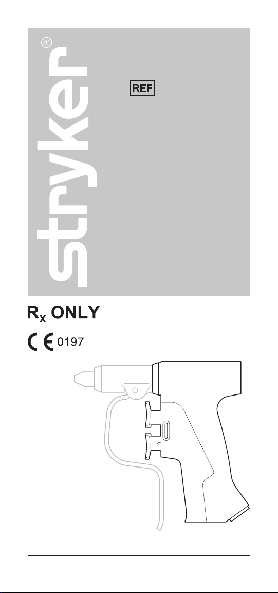
Stryker RemB User manual

2018-10 6400-099-700 Rev-AA www.stryker.com
Instructions For Use
RemB®Electric
Universal Driver
6400-099-000
ENGLISH (EN)

2 www.stryker.com
EN 6400-099-700 Rev-AA
Introduction
This Instructions For Use manual is the most comprehensive source
of information for the safe and effective use of your product. This
manual may be used by in-service trainers, physicians, nurses,
surgical technologists, and biomedical equipment technicians.
Keep and consult this reference manual during the life of the
product.
The following conventions are used in this manual:
• A WARNING highlights a safety-related issue. ALWAYS comply
with this information to prevent patient and/or healthcare staff
injury.
• A CAUTION highlights a product reliability issue. ALWAYS comply
with this information to prevent product damage.
• A NOTE supplements and/or clarifies procedural information.
For additional information, especially safety information, or in-
service training, contact your Stryker sales representative or call
Stryker customer service. Outside the US, contact your nearest
Stryker subsidiary.
NOTE: The RemB Electric Universal Driver (handpiece) is also
known as the RemB Universal Driver.
Indications For Use
The Stryker Consolidated Operating Room Equipment (CORE™)
System is intended for use in the cutting, drilling, reaming,
decorticating, shaping, and smoothing of bone, bone cement and
teeth in a variety of surgical procedures, including but not limited
to orthopedic, dental, ENT (ear, nose, throat), neuro, spine, and
endoscopic applications. It is also usable in the placement or
cutting of screws, metal, wires, pins, and other fixation devices.
Contraindications
None known.

6400-099-700 Rev-AA EN
www.stryker.com 3
User/Patient Safety
WARNINGS:
• Before using this equipment, or any component compatible with
this equipment, read and understand the instructions for use.
Pay particular attention to safety information. Become familiar
with the equipment before use.
• Only healthcare professionals trained and experienced in the
use of this medical device should operate this equipment.
• The healthcare professional performing any procedure is
responsible for determining the appropriateness of this
equipment and the specific technique for each patient. Stryker,
as a manufacturer, does not recommend surgical technique.
• ALWAYS allow the equipment to reach the specified operation
temperature range before use. See the Specifications section.
• Upon initial receipt and before each use, clean and sterilize
the equipment as indicated. See the care instructions manual
supplied with the equipment.
• Upon initial receipt and before each use, inspect each
component for damage. DO NOT use any equipment if damage
is apparent or the inspection criteria are not met. See the care
instructions manual supplied with the equipment.
• DO NOT use this equipment in areas in which flammable
anesthetics or flammable agents are mixed with air, oxygen, or
nitrous oxide.
For Use With
DESCRIPTION REF
TPS™ Consoles with software version
4.0 and higher
5100-0XX-000 Series
CORE Powered Instrument Driver
(console) with software version 5.7 or
higher
5400-050-000
CORE 2 Console 5400-052-000
Accessories
WARNINGS:
• Use only Stryker-approved equipment, unless otherwise
specified.
• DO NOT modify any equipment without the authorization of the
manufacturer.

4 www.stryker.com
EN 6400-099-700 Rev-AA
Accessories (continued)
WARNINGS:
• DO NOT reuse, reprocess, or repackage a single use device.
A single use device is intended for a single use only. A single
use device may not withstand chemical, chemical vapor, or
high temperature sterilization reprocessing. Design features
may make cleaning difficult. Reuse may create a serious risk
of contamination and may compromise the structural integrity
of the single use device resulting in operational failure. Critical
product information may be lost if the single use device is
repackaged. Failure to comply may lead to infection or cross-
infection and result in patient and/or healthcare staff injury.
• All cutting accessories are intended for single use only. Reuse
significantly increases wear on the handpiece and attachment.
• Wobbling may cause inaccurate wire or pin placement and/
or bone or tissue damage. If wobbling occurs, see the
Troubleshooting section.
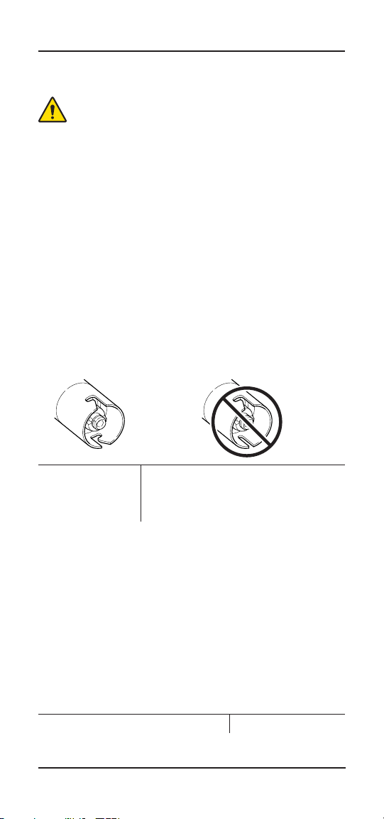
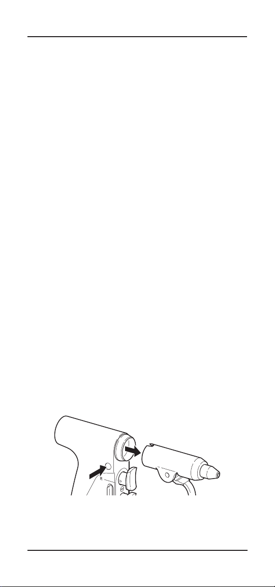
• When using the Universal Driver, always use Stryker
attachments with two J-slots. The Universal Driver will not fully
retain Stryker attachments with only one J-slot.
Use attachments
with two J-slots.
DO NOT use earlier versions of the
Stryker Wire Collet (REF 4100-062-000)
or Pin Collet (REF 4100-125-000). Both
collets have only one J-slot.
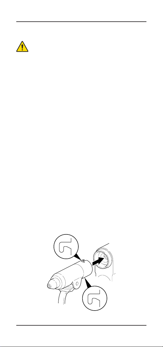
A variety of specialized attachments are available for use with
the handpiece. Each attachment has a specialized retainer for
wires, pins, tools or cutting accessories. See the Cordless Driver
and Universal Driver Attachments Instructions For Use for specific
attachment and accessory instructions.
NOTES:
• Cutting accessories are sterilized using irradiation.
• For a complete list of accessories, contact your Stryker sales
representative or call Stryker customer service. Outside the US,
contact your nearest Stryker subsidiary.
The following Stryker-approved accessories are sold separately:
DESCRIPTION REF
Handpiece Cord 5100-004-000

6400-099-700 Rev-AA EN
www.stryker.com 5
Features
Handpiece
A
F
E
B
D
C
G
H
A Release Button – Press to release an attachment from
the handpiece.
B Attachment Connector
C Applied Part – The distal end of the handpiece and
the attachment (as defined by the Product Safety
Certification standards listed in the Specifications section
of the instructions for use supplied with the console.)
D Attachment
E Reverse Trigger – Press this pressure sensitive trigger to
obtain variable speed reverse operation.
F Forward Trigger – Press this pressure sensitive trigger to
obtain variable speed forward operation.
G Cord Receptacle
H Function Switch – Adjust this switch to the desired
function. Functions and switch positions are described
below.

6 www.stryker.com
EN 6400-099-700 Rev-AA
Features (continued)
Function Switch
SAFETY – Fully depress the
switch to lock both triggers.
FORWARD – Center the switch
to lock the reverse trigger. The
forward trigger is functional.
FORWARD/REVERSE – Fully
extend the switch to unlock
both triggers. Both triggers are
functional.
Definitions
The symbols located on the equipment and/or labeling are defined
in this section or in the Symbol Definition Chart. See the Symbol
Definition Chart supplied with the equipment.
SYMBOL DEFINITION
REVERSE TRIGGER
FORWARD TRIGGER
SAFETY
FORWARD
FORWARD/REVERSE
Cord Alignment Mark
General warning sign

6400-099-700 Rev-AA EN
www.stryker.com 7
Instructions
WARNINGS:
• ALWAYS operate the equipment within the specified
environmental condition values. See the Specifications section.
• DO NOT attempt to insert or remove any cutting accessory while
the handpiece is operating.
• ALWAYS follow the recommended duty cycle to prevent the
equipment from overheating. See the Specifications section.
• Use adequate irrigation during cutting to prevent heat
generation.
• Before operating the handpiece, gently tug the attachment to
verify the attachment is secure.
• ALWAYS set the function switch to the SAFETY position while
the handpiece is idle, when passing the handpiece to another
person, or before inserting or removing a cutting accessory or
attachment.
• DO NOT press the pedal of a connected footswitch while the
function switch is set to the SAFETY position. An accidental
pedal press will override the SAFETY position and activate the
handpiece.
CAUTION: During an endoscopic procedure, DO NOT introduce the
handpiece through the same orifice as the endoscope.
NOTE: See the Cordless Driver and Universal Driver Attachments
Instructions For Use for specific attachment and accessory
instructions.
To Install an Attachment
1. Vertically align the two J-slots on the attachment with the
attachment connector.
2. Insert the attachment into the attachment connector until it
snaps into place.
3. Gently tug the attachment to verify the attachment is secure.

8 www.stryker.com
EN 6400-099-700 Rev-AA
Instructions (continued)
To Operate the Handpiece
NOTE: See the instructions for use supplied with the appropriate
console for additional information about handpiece operation.
1. Install an accessory into the attachment.
NOTE: See the instructions for use supplied with the attachment to
properly install an appropriate accessory.
2. Plug one end of the cord into the handpiece cord receptacle
and the other end of the cord into the appropriate console cord
receptacle.
3. Use the console to program the operational settings of the
handpiece as required.
NOTES:
• When using the console, the Forward and Reverse buttons on
the Universal Driver Screen do not function. Use the handpiece
triggers or a footswitch to select the handpiece direction.
• When using the console, the Oscillate button will initiate a
turn-based oscillate mode that defaults to a one-turn oscillation.
Use the console touchscreen to select more turns as required.
• Depress both triggers together to operate the handpiece in the
oscillate mode.
• Pressure on a trigger will also control the speed of the
handpiece.
4. Use either the handpiece triggers or a footswitch to operate the
handpiece.
NOTE: Use the console touchscreen to assign different functions
(such as the oscillate mode) to the footswitch pedals as required.
To Remove an Attachment
1. Fully depress the release button.
2. Firmly grasp and pull the attachment from the attachment
connector.
Final Disassembly
1. Unplug the cord from the console and from the handpiece.
2. Remove attachment as described above.

6400-099-700 Rev-AA EN
www.stryker.com 9
Troubleshooting
WARNING: DO NOT disassemble or service this equipment
without the authorization of the manufacturer.
NOTE: For service, contact your Stryker sales representative or call
Stryker customer service. Outside the US, contact your nearest
Stryker subsidiary.
PROBLEM CAUSE ACTION
The console
fails to recognize
the handpiece
or displays a
handpiece error
message.
The console
software is not
compatible with the
handpiece.
Contact Stryker
to obtain console
upgrade information.
An electrical
malfunction exists.
Return the
handpiece for repair.
The handpiece
will not operate.
The function switch
is in the SAFETY
position.
Set the function
switch to the
FORWARD or
FORWARD/REVERSE
position.
An electrical
malfunction exists.
Return the
handpiece for repair.
The handpiece
operation is
rough or slow.
An electrical
malfunction exists.
Return the
handpiece for repair.
The attachment
wobbles.
The wire or pin
extends too far from
the distal end of the
handpiece, is the
wrong size, or is not
properly centered in
the attachment.
Reinsert the wire or
pin. If the attachment
continues to wobble,
return the handpiece
for repair.
The pin slips in
Pin Collet (REF
4100-125-000).
Design limitations
exist.
Use Pin Collet (REF
4100-126-000).

10 www.stryker.com
EN 6400-099-700 Rev-AA
Troubleshooting (continued)
PROBLEM CAUSE ACTION
The function
switch does
not operate as
expected.
The switch
position symbols
were not used to
set the function
switch.
Look at the switch
position symbols
on the side of the
handpiece to properly
set the function
switch.
The attachment is
difficult to install
and/or interference
is experienced
during installation.
The release button
mechanism needs
lubrication.
See the care
instructions manual
supplied with the
equipment.
Sporadic electrical
interference is
experienced.
Electrical noise is
present.
Turn off all electrical
equipment not in use
in the operating room.
Relocate electrical
equipment; increase
spatial distance.
Plug operating room
equipment into
different operating
room outlets.
Care Instructions
For processing instructions and disposal/recycle information, see
the care instructions manual supplied with the equipment.

6400-099-700 Rev-AA EN
www.stryker.com 11
Specifications
WARNING: ALWAYS check any documentation that
accompanies attachments and/or cutting accessories for
special duty cycle and usage instructions.
Model: RemB Electric Universal Driver
(REF 6400-099-000)
Dimensions: 5.3 inch [136 mm] height
1.02 inch [26 mm] width
5.47 inch [139 mm] length
Mass: 1.18 lb [0.53 kg]
Speed: 1500 rpm
Mode of Operation:
Duty Cycle:
Rest Between Cycles:
Non-continuous Operation
20 seconds on/20 seconds off, 6 times
45 minutes
Power Supply: Stryker CORE 2, CORE, or TPS
Console
40 V (Direct Current)
Equipment Type:
Type BF Applied Part
Maximum
Temperature of
Applied Part:
Less than 124 °F [51 °C] (Maximum
surface temperature as tested to the
standards listed under Product Safety
Certification in the instructions for use
supplied with the console.)
Ingress Protection: IPX0 Ordinary Equipment
Environmental
Conditions: Operation
Storage and
Transportation
Temperature
Limitation:
Humidity
Limitation:
Atmospheric
Pressure
Limitation:

2018-10 6400-099-700 Rev-AA www.stryker.com
Stryker Instruments
4100 E. Milham
Kalamazoo, Michigan
(USA) 49001
1-269-323-7700
1-800-253-3210
ES/DE/FR/IT/NL 6400-099-713
JA/ZH/KO 6400-099-720
SV/DA/FI/PT/NO 6400-099-730
PL/EL 6400-099-750
This manual suits for next models
1
Table of contents