Stuart Turner BEP 130 Manual

Installation, Operatation & Maintenance
Instructions
Please leave this instruction booklet with the home owner as it contains important guarantee,
maintenance and safety information
BEP 130
Pt. No. 46727
BEP 150
Pt. No. 46728
Read this manual carefully before commencing installation.
This manual covers the following products:
1
CE compliant product
STUART

- 2 -
Cont...
PRODUCT DESCRIPTION
The Electrastream unit is a packaged hot water and central heating unit designed to provide hot
water and wet heating to water filled radiators, using electricity as the primary fuel.
The Electrastream is a 9 kW (30,000 btu) system suitable for flats, apartments, offices and other
small dwellings.
STORAGE
If this product is not to be installed immediately on receipt, ensure that it is stored in a dry, frost
and vibration free location in its original packaging.
CONTENTS Page
Checklist .................................................................4
Locations ................................................................5
Key Features .............................................................8
Pipework Connections .....................................................9
Electrical Installation .......................................................13
Commissioning ...........................................................16
Maintenance/Servicing .....................................................24
Technical Specification .....................................................26
Trouble Shooting ..........................................................27
Guarantee ...............................................................29

- 3 -
Cont...
WARNINGS:
zDO NOT remove or adjust any component part of the unvented water heater:
contact the INSTALLER.
zPlumbing must remain as supplied, do not add to or change any plumbing or
connections.
zIn the event of hot water/steam being emitted at the discharge pipe or tundish,
switch the system off and contact installer – refer to trouble shooting.
zScalding water and steam can be emitted from the discharge pipe. In accordance
with guidelines position the discharge so there is no hazard to property or people
(especially children).
zThis installation is subject to Building Regulation Approval, notify the Local Authority
of intention to install. Use only Manufacturer’s recommended replacement parts.
zWarning: ISOLATE THE TRI-CORE HEATER BEFORE REMOVING ITS COVER.
zWarning: The water temperature setting must not be set above 65 oC to avoid
scalding.
zUnder no circumstances should the system be operated without the cylinder TPRV
fitted and working correctly.
zPlastic pipe and fittings must not be used within 1 metre of the cylinder
zAll wiring must be carried out to and comply with current IEE wiring Regulations.
and comply with any relevant regulation that apply at the time of the installation.
zUsing incorrect cable size will invalidate the warranty. Loose connections will result
in overheating, arcing and possibly fire. ENSURE ALL CONNECTIONS ARE TIGHT.
zEnsure that no water can come into contact with any electrical device before the
electrical supply is turned back on.
zThe Electrastream unit must be commissioned by a competant person, failure to do
so will invalidate the guarantee.
zAlways turn off the heating system and electricity supply to the Electrastream
before removing covers and working on the Electrastream System.
zAny service requirements of specific components must be carried out to the
specified manufacturer’s instructions.
zTo install an Electrastream Heating System the installer must be fully competent,
suitably qualified and hold a relevant unvented certificate and any applicable
licence that may be require by the local inspectorate for installation of an unvented
hot water storage system.
In some areas the Local Authority may require notification by means of a building
notice or by the submission of full plans for the proposed installation of an unvented
hot water storage system.
Note: In some areas it is a criminal offence to install an unvented hot water storage
system without notifying the local authority or without the relevant licence.
zThe Water Bye-laws and Current Building Regulations (paying particular attention
to G3 and Part L 1 & 2) and HSE requirements should be considered when installing
an Electrastream system.
Please read installation details carefully as they are intended to ensure this product provides
long, trouble free service. Failure to install the unit in accordance with the installation
instructions will lead to invalidation of the warranty.
This product must be installed by a competent person and must not be modified in any way.

- 4 -
Cont...
CHECKLIST
IMPORTANT: With the appliance removed from its packaging check for any damage prior to
installation. If any damage is found contact Altecnic Ltd within 24 hours of receipt.
Item Description Qty Item Description Qty
Electrastream unit 1 22 mm lever isolating
valve 2
A B
Fig. 1
B
A

- 5 -
Cont...
1 LOCATION GENERAL
1.1 Siting the Electrastream unit:
Note: The Electrastream units are designed for indoor use only.
The cylinder must always be installed vertically, at a convenient above ground location
within the property. As the Electrastream is part of a sealed system, the cylinder is
equally effective on any floor. The floor must give adequate support to the filled
cylinder, refer to weights in Fig. 2.
The Electrastream must not be installed in any enclosed space where the air
temperature could exceed the maximum electrical design ambient of 30 °C. Adequate
ventilation should be provided for airing cupboards and enclosed compartments.
Humidity may also present a problem within airing cupboards.
For servicing and cylinder replacement, clearance is required all round the cylinder –
recommended 100 mm minimum.
The cylinder may be installed below ground i.e. in a basement, providing that the
expansion relief discharge pipe is plumbed to a metal receptacle with a suitable
pump and switch arrangement in accordance with, current Building Regulations.
A
B
645
O576
720
510
200
100
250
701
396
Fig. 2
Cylinder
Model Capacity A B *Weight
Empty
*Weight
Full
BEP 130 130 litres 1200 mm 957 mm 49.5 kg 179.5 kg
BEP 150 150 litres 1325 mm 1085 mm 54.5 kg 204.5 kg
Water mains in – 22 mm
Hot water connection – 22 mm
Heating return – 22 mm
Heating flow – 22 mm
C – Minimum space
required in the event of a
replacement part
C
C

- 6 -
Cont...
1.2 Frost protection: The Electrastream unit must be located in a dry position, frost free
and protected from freezing, particularly when installed in a loft.
To comply with Building Regulations, all necessary pipework must be suitably lagged.
1.3 Connecting the water supply: All pipework should be installed using good plumbing
practice. We recommend 22 mm mains cold water supply is used to avoid performance
loss.
1.4 Scale protection:
zIn areas of hard water, determined by the calcium content being 200 ppm
or greater, an effective water conditioner must be installed in the cold feed
to avoid damage and invalidation of the guarantee.
zSuitable water conditioning devices include the Stuart Catalytic Water
conditioner model C3–22 (product code 46617). For installations requiring
flow rates in excess of 22 litres/min please contact Stuart Turner Ltd for
guidance.
zDamage caused by scale will invalidate the guarantee.
Higher water temperatures of 65 °C and above can cause excessive scale.
The location and position of the water conditioner should be as per the manufacturer’s
recommendations.
1.5 Check water pressure & flow rates: Stuart Turner recommends 1.5 bar pressure at 20
litres/minute flow rate as the minimum requirements for satisfactory operation. The
unit will still operate below this, but it may not be possible to run two or more outlets
at the same time.
1.6 Pipework to taps: Ideally 22 mm pipe should supply the outlets throughout the
property with short lengths (max 1 metre) runs of 15 mm going to baths, showers, and
basin taps. Smaller bore pipe can be used to suit taps but may lead to loss of
performance.
1.7 Shut off valves: Lever valves are supplied separately and must be fitted as close as
possible to the unit on the mains cold supply feed to the combination valve and to the
blending valve (see Fig. 3) feeding hot water services.
1.8 Drain valve: A drain valve is incorporated onto the pipework to be used to drain the
cylinder, when required during commissioning or maintenance (Fig. 4) to allow for
maintenance work.

- 7 -
Cont...
1.9 System layout schematic:
1.10 Mains pressure reducing valve (not supplied): If the mains pressure is more or
fluctuates above 4 bar, a mains pressure reducing valve must be fitted to the cold
services in order to balance hot/cold water supplied. This should be positioned as
shown, refer to schematic in Fig. 3.
1.11 Bypass (not supplied): An automatic bypass valve should be fitted between the flow
and return of the heating system, normally after the pump but before any radiator take
offs. The valve must be set to suit the pressure of the system, refer to the manufacturer’s
instructions.
1.12 Room thermostat (not supplied): A standard room thermostat with no built in timers or
functions is recommended.
Important: When a programmable room thermostat is used it should only be set to
call for heat when ‘Economy Tariff’ is available.
Fig. 3
Heating return
Heating flow
to radiators/
kickspace
heater/towel
rails
Bypass
Discharge
Isolating valve
Isolating valves
Hot supply to taps and
thermostatic showers
Water
conditioner
3.5 bar pressure
reducing valve
(not supplied)
Single check valve
(not supplied)
Mains stopcock
Incoming
mains
supply
Cold supply
to taps
Mains electrical supply

- 8 -
Cont...
2 KEY FEATURES
Fig. 4
Heating expansion
vessel 8 litre
Hot water expansion
vessel 12 litre
Schrader valves
(under caps)
Temperature
sensor (in box)
Over temperture
cut-out thermostat
Tricore heater 3 off
3 kW elements
Electrastream control unit
Consumer unit (includes DP isolator,
RCD & MCB)
Cylinder TPR valve – 6 bar
Thermostatic mixing vlave
Hot water outlet – 22 mm connection
Cold water supply – 22 mm connection
Combination valve
(including hot water PRV – 6 bar)
Tundish
Drain valve
Unvented cylinder
Heating PRV – 3 bar
Pressure gauge
Motorised valve
Heating circulating
pump & valves
Heating flow – 22 mm connection
Heating return – 22 mm
Note: Image shown
with cables removed
Important: Plumbing must
remain as supplied.
Do not add or change any
plumbing or connections.

- 9 -
Cont...
3 PIPEWORK CONNECTIONS
3.1 Hot/cold services: The cold water mains supply is connected to the combination valve
via the lever isolating valve supplied, which limits incoming pressure to 3.5 bar and has
an integral NRV.
The hot water outlet pipework is connected to the outlet of the mixing valve via the
lever isolating valve supplied.
Provision should also be made in the cold services to tee/feed cold outlets prior to the
Electrastream connection.
Both of these connections are for 22 mm pipe.
3.2 Heating system:
a) The total output from the Electrastream for hot water and heating is 9 kW @ 240 V
having a maximum output of 30,000 BTU and should be sized for systems requiring
no more than this.
b) The heating system pipework is connected to the underside of the circulating pump.
The return pipework from the heating system is to be connected to the bottom of
the coil, to the short pipework that is also connected to the filling loop.
Fig. 5
Incoming
mains
supply
Hot water supply
Heating
flow
Heating
return
Fig. 6

- 10 -
Cont...
3.3 Tundish: The Electrastream unit is supplied with a temperature & pressure relief (TPR)
valve and Pressure relief (PR) valve fitted and plumbed to the Tundish. The unit must
be positioned to allow the tundish to be visible to the occupants and away from
electrical services. The discharge pipe from the tundish should terminate in a safe place
where there is no risk to persons in the vicinity of the discharge and be made of metal.
The discharge pipe must be 22 mm copper pipe. Regulations do not permit more than
3 × 90 degree bends between the Electrastream unit and the outflow. Between the TPR
and the first 90 degree bend there must be a fall of at least 300 mm. The fall of the
pipework must be continuous and the pipe should terminate in the gully or be bent
backwards onto an outside in a place where discharge cannot be injurious to persons.
Warning: Scalding water and steam can be blown out of the discharge
pipe. Position the discharge so that it is not a hazard to property or people
(especially children).
3.4 Dishcharge pipework:
G3 Requirement
‘… there shall be precautions… to ensure that the hot water discharged from safety
devices is safely conveyed to where it is visible but will not cause danger to persons in
or about the building.’
G3 Guidance Section 3.5
The discharge pipe (D1) from the vessel up to and including the tundish is supplied by
Stuart Turner Ltd. Where otherwise the installation should include the discharge pipe(s)
(D1) from the safety device(s). In either case the tundish should be vertical, located in
the same spaces as the unvented hot water storage system and be fitted as close as
possible to, and lower than, the safety device, with no more than 600 mm of pipe
between the valve outlet and the tundish.
3.5 The discharge pipe (D2): The discharge pipe (D2) from the tundish should:
Have a vertical section of pipe at least 300 mm long below the tundish before any
elbows or bends in the pipework.
Be installed with a continuous fall of at least 1 in 200 thereafter.
The discharge pipe (D2) should be made of metal or other material that has been
demonstrated to be capable of safely withstanding temperatures of the water
discharged and is clearly and permanently marked to identify the produce and
performance standard (e.g. as specified in the relevant part of BS 7291–1:2006
Thermostatic pipes and fittings for hot and cold water for domestic purposes and
heating installations in buildings, General Requirements).
3.6 Termination of discharge pipe: The discharge pipe (D2) from the tundish should
terminate in a safe place where there is no risk to persons in the vicinity of the
discharge.
Examples of acceptable discharge arrangements are:
To a trapped gully in the end of the pipe below a fixed grating and above the water
seal.
Downward discharges at low level; i.e. up to 100 mm above external surfaces such as
car parks, hard standings, grassed areas etc. are acceptable providing that a wire cage
or similar guard is positioned to prevent contact, whilst maintaining visibility.
Discharges at high level: e.g. into a metal hopper and metal downpipe with the end of
the discharge pipe clearly visible or onto a roof capable of withstanding high
temperature discharges of water and 3 metres from any plastic guttering system that
would collect such discharges.
The discharge would consist of high temperature water and steam. Asphalt, roofing felt
and non-metallic rainwater goods may be damaged by such discharges.

- 11 -
Cont...
Where a single common discharge pipe serves more than one system, it should be at
least one pipe size larger than the largest individual discharge pipe (D2) to be
connected.
The discharge pipe should not be connected to a soil discharge stack unless it can be
demonstrated that the soil discharge stack is capable of safely withstanding
temperatures of the water discharged, in which case it should:
a) Contain a mechanical seal, not incorporating a water trap, which allows water into
the branch pipe without allowing foul air from the drain to be ventilated through the
tundish;
b) Be a separate branch pipe with no sanitary appliances connected to it;
c) If plastic pipes are used as branch pipes carrying discharge from a safety device
they should be either Polybutalene (PB) to Class S of BS 7291–2:2006 or cross linked
polyethylene (PE-X) to Class S of BS 7291–2:2006; and
d) Be continuously marked with a warning that no sanitary appliances should be
connected to the pipe.
Fig. 7
Typical discharge pipe arrangement

- 12 -
Cont...
3.7 Worked example and pipe sizing:
The example below is for a G½ 6 with a discharge pipe (D2) having 4 No. 22 mm elbows
and length of 7 m from the tundish to the point of discharge.
From Table 1:
Maximum resistance allowed for a straight length of 22 mm copper discharge pipe (D2)
from a G ½ temperature relief valve is: 9.0 m
Subtract the resistance for 4 No. 22 mm elbows at 0.8 m each = 3.2 m
Therefore the maximum permitted length equates to: 5.8 m which is less than the actual
length of 7 m therefore calculate the next largest size.
Maximum resistance allowed for a straight length of 28 mm copper discharge pipe (D2)
from a G ½ temperature relief valve is: 18 m
Subtract the resistance for 4 No. 28 mm elbows at 1.0 m each = 4 m
Therefore the maximum permitted length equates to: 14 m
As the actual length is 7 m, a 28 mm (D2) copper pipe will be satisfactory.
Valve outlet
size
Minimum size of
discharge to Tundish
(D1)*
Minimum size of
discharge pipe from
Tundish (D2)*
Maximum resistance
allowed expressed as a
length of straight pipe, i.e.
no elbows or bends
Resistance created by
each elbow or bend
G ½ 15 mm
22 mm
28 mm
35 mm
up to 9 m
up to 18 m
up to 27 m
0.8 m
1.0 m
1.4 m
G ¾ 22 mm
28 mm
35 mm
42 mm
up to 9 m
up to 18 m
up to 27 m
1.0 m
1.4 m
1.7 m
G 1 28 mm
35 mm
42 mm
54 mm
up to 9 m
up to 18 m
up to 27 m
1.4 m
1.7 m
2.3 m
- 13 -
Cont...
4 ELECTRICAL INSTALLATION
4.1 Regulations: The electrical installation must be carried out in accordance with the
current national electrical regulations and installed by a qualified person.
4.2 Before starting work on the electrical supply ensure power supply is isolated.
4.3 DO NOT allow the supply cord to contact hot surfaces
4.4 DO NOT switch the power on until the unit has been filled with water and has been
earthed.
4.5 Safety: The mains supply to the unit must be connected through the 40 Amp RCD
(fitted).
4.6 Electrical supply: The main incoming electrical supply to the property should be of
adequate voltage, current and temperature rating for the requirements of the
Electrastream as well as all other electrical requirements within the property. It is
advised to turn the switch off when hot water and heating are not required i.e. holidays
etc.
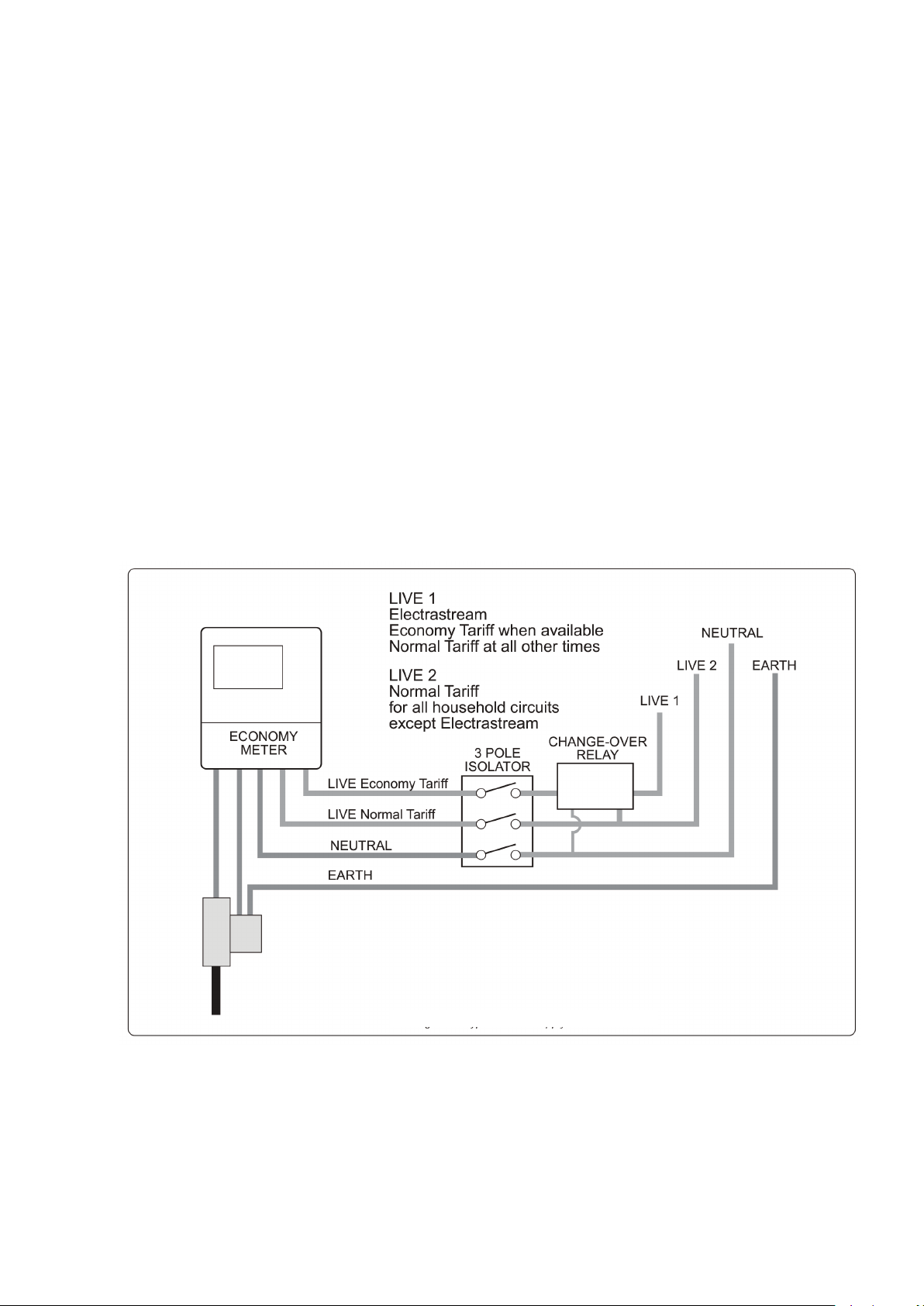
4.7 Off – peak electrical supply: To achieve the most efficient performance from the
Electrastream it is strongly recommended to use an ‘Economy 18’ Off-Peak electrical
supply. Other off-peak options such as ‘Economy 7’ or ‘Economy 10’ tariffs are also
available from most UK electrical suppliers.
Consult the local electricity suppliers to determine what economy tariff options are
available before installing the Electrastream.
4.8 Typical power supply: Figure 8 shows a typical power supply for economy meters.
Consult electricity supply company for specific requirements.
Fig. 8 Typical power supply

- 14 -
4.10 Wiring of the unit: The Electrastream Unit is supplied wired, therefore only a mains
cable (not supplied) is required to be installed through the cable gland located at the
top of the RCD box. This 3 core cable suitably sized is connected into the live, neutral
and earth of the RCD.
LN
E
Fig. 9
Earth
Brown
Blue
Mains cable supply

- 15 -
Cont...
Fig. 10 Wiring diagram – standard arrangement

- 16 -
Cont...
5 COMMISSIONING
5.1 IMPORTANT it is the responsibility of the installer to ensure that the Electrastream
System is properly commissioned. Should the commissioning not be carried out, then
the manufacturers guarantee and any extended warranty, will become null and void.
Wet System
5.2 System flushing: The pipework system should be flushed out prior to the Electrastream
being connected to ensure any contaminants/chemical residues and foreign bodies are
removed from elsewhere in the system.
5.3 Expansion vessel pressure – hot water: (Cream vessel)
The air pressure should be set to 0.1 bar greater than the system pressure and must be
set as part of the commissioning procedure.
Capacity 12 litres
If the hot water vessel needs to have its air charge checked or replenished, it should be
carried out as follows:
a) Isolate unit electrically
b) Isolate water supply using the isolating valves
c) Release the system water pressure by opening a system outlet (tap)
d) Check air charge at Schrader valve (under the cap) using a tyre pressure gauge
e) Replenish air charge to suit the system if required by injecting air into the vessel via
the Schrader valve using a car or bicycle pump, ensuring a system outlet valve
remains open during this procedure to allow the vessel to exhaust any excess water.
f) Close all systems taps, open the isolating valves and turn on electrical power.
g) After the pressure has been changed, commission the unit see Section 5.5 onwards.
5.4 Expansion vessel pressure – heating system: (Grey vessel)
Maximum charge pressure 1.5 bar
Maximum working temperature 90 °C
Maximum Working Pressure 3 bar
Capacity 8 litres (for maximum system expansion of 7 litres)
The vessel pre charged is factory set to 1.9 bar, therefore it must be adjusted to suit the
system before commissioning continues.
The expansion vessel is supplied mounted on the unit, this is suitable for systems with a
static head of up to 5 metres. If the static head is greater than 5 metres the charge
pressure of the expansion vessel will need to be increased. Increase the pressure using a
standard car tyre pump and pressure gauge when the system is empty (zero pressure).
Expansion vessels are suitable for systems requiring a maximum expansion of 7 litres
as detailed above. For systems requiring more expansion a second expansion vessel will
be required. BS7074 Part 1 includes information on this requirement.
Note: Normally expansion requirement is 4% of the system water content including the
unvented cylinder coil
5.5 Hot water system pre-fill check:
a) Check the hot water heating discharge pipes and tundish are correctly installed to
conform to the Building Regulations G3.
b) Check all pipe connections are water tight.
c) Check the drain valve is closed.
d) If fitted, check that the Scale Protection Device or water softener has been fitted
according to manufacturer’s instructions.
5.6 Filling hot water system:
a) Open all shut off valves
b) Open the incoming water isolating valve (mains stopcock) to the Electrastream and
allow the unit to fill.
c) Open all domestic taps in turn to purge the air
d) Check system for leaks including around the Tri-Core heater.
e) Check no water is discharging from any relief valves.

- 17 -
f) Test the operation of the Temperature & Pressure relief valve by turning the manual
test cap and ensure the water flows freely and safely to waste.
g) Test the operation of the combination valve PRV by turning the manual test cap and
ensure the water flows freely and safely to waste.
h) Set hot water Mixing valve to ‘max’.
5.7 Heating system pre-fill check:
a) Check filling loop is fitted correctly
b) Check all radiator valves are fitted and tight.
c) Check all radiator air vents are closed.
d) Check all drain valves are closed.
5.8 Flushing and filling heating system:
a) Carry out fill only after hot water system has been flushed and cleaned.
b) Close all radiator valves.
c) Connect filling loop and fill heating pipes using last radiator in line to bleed air.
d) Check for leaks
e) Using hose or suitable container, drain heating pipes.
f) Repeat flushing pipes as required and fill.
g) Open radiator valves and bleed air to fill all radiators.
h) Drain heating system again.
i) On final refill, add proprietary additives as manufactures instructions. Fill to 1 bar.
j) Set pressure gauge red arrow to the black arrow (cold fill pressure – 1 bar).
Electrical
5.9 Electrical check:
a) Check that all wiring including earth wiring has been installed correctly
b) Check tri-core heater cover, Electrastream controller cover and all other electrical
covers are correctly fitted.
c) Check tundish is positioned so that any spillage or spray from the tundish would not
contact any electrical components and is visible.
d) Check ALL wiring connections have been made
e) Check the required earth continuity conductors have been fitted.
5.10 Setting and testing controls:
a) Switch on Electrastream mains isolator.
b) On the Electrastream control unit, set date and time (see Fig. 12)
c) Set times to suit economy tariff.
d) Set target temperature to 65°C
e) If heating/hot water is not On press Boost and set room thermostat for heat.
f) Wait for the cylinder and heating to heat up.
g) Check for leaks and bleed the system again when it is up to temperature.
h) Check pressure gauge black arrow, this will show the heating system working
pressure. This should be less than 2.8 bar.
i) Check operation of the Electrastream control unit – Fig. 11.
j) When timer is set for heat and the room thermostat is set above the ambient – the
motorised valve should be open and the pump should be running. When the room
thermostat is reset below ambient the pump should stop and the valve should close.
When the timer is not set for heat, the pump should no run and the valve should be
closed regardless of room thermostat setting.
k) Fill in details in the log book.

- 18 -
Cont...
5.11 Overview of control unit:
Fig. 11 Electrastream control unit – normal screen
For display settings see Fig. 12
For error displays see 8.1
HEAT 1 ^ Indicates Eleement 1 is ON HEAT 1 ! Indicates heater element has failed – see 5.17
HEAT 2 ^ Indicates Eleement 2 is ON HEAT 2 ! Indicates heater element has failed – see 5.17
HEAT 3 ^ Indicates Eleement 3 is ON HEAT 3 ! Indicates heater element has failed – see 5.17
VALVE Inidcates Heating Valve is OPEN
PUMP Indicates Heating Pump is ON
THERM Indicates Room Stat is calling for heat
TEST 1......5 Indicates heater test is being performed after midnight, this may take up to 30 minutes
Heating on
^
^
^

- 19 -
Cont...
Fig. 12 Electrastream control unit – display settings
For error displays see 8.1

- 20 -
6 GENERAL OPERATION
6.11 Heating motorised valve: When the room thermostat is calling for heat and the
Electrastream control unit is set for heat ON, the heating motorised valve will open
allowing water to the radiators.
Display icon ‘Valve V’ indicates valve is open
6.12 Pump: The heating circulating pump is controlled by Electrastream Control Unit in
response to the room thermostat.
The pump has 3 speeds, it is normally set to speed 2 (II). Consult Electrastream installer
before changing this setting.
Display icon ‘Pump V’ indicates the pump is ON.
6.13 Room thermostat:
IMPORTANT: When a programmable room thermostat is used it should only be set to
call for heat when ‘Economy Tariff’ is available.
The room thermostat controls the heat within the property.
When the room thermostat is calling for heat and the Electrastream control unit is set
for heat ON, the heating circulating pump will run, pumping water through the
radiators.
Display icon ‘Therm V’ indicates the room thermostat is calling for heat.
6.14 TRI-CORE heater elements: The three elements heat the water in the cylinder when the
Electrastream control unit is programmed for a heat cycle. The elements are switched
on and off by the control unit in response to the temperature within the cylinder as
detected by the temperature sensor. They have a staggered switch on sequence that
prevents sudden high load on the power supply.
The control unit also limits the use of the elements for efficiency.
For example: When the hot water within the cylinder is within 2° of the set Target 65 °C,
only one element will be on. When the hot water is between 2° and 4 °C below the set
target, then two elements will be on. When the hot water within the cylinder is below
6 °C of the set target, then all three elements will be on.
Display icons ‘Heat 1 ^’, ‘heat 2 ^’ and ‘heat 3 ^’ indicate that the elements are heating. If
a ‘!’ is displayed, this indicates a fault with the element, see Section 9.1.
6.15 Residual current device (RCD) : The Electrastream system will be protected by a
residual current device, this will automatically switch off the electric supply if an earth
fault develops. This should be tested at least every three months.
6.16 Element resettable thermal trips: Each of the three elements of the tri-core heater is
protected by a 16 Amp Resettable thermal trip, these have their reset buttons located
on the front of the Electrastream Control Unit (see Fig 13).
In the event of electrical overload on an element the relevant thermal trip will trip out,
when this occurs the button will pop up and the screen will display ‘!’ under the
relevant heat.
To reset the thermal trip:
1. Turn OFF the Electrastream mains isolating switch
2. Look at the three buttons; button(s) that are
protruding have tripped out.
3. Press the button in, if the button stays in when the
power is turned on, then trip has been reset.
However if the button pops out again a possible
fault exists – contact the installer.
The Electrastream will still operate with one or two
elements working, but this is not satisfactory and the
installer must be contacted to rectify the fault as soon
as possible.
CAUTION
HIGH VOLTAGE!
DO NOT REMOVE ANY
COVERS (INCLUDING
ROOM THERMOSTAT)
BEFORE ISOLATING THIS
UNIT
Fig. 13 Resettable thermal trips
This manual suits for next models
1
Table of contents
Popular Heating System manuals by other brands

Jaga
Jaga Mini Canal Mounting instructions

Carrier
Carrier 40VMH024 Installation and maintenance instructions

Oxygen
Oxygen X-Air V600 Installation and operation manual

Daikin
Daikin DCC Series installation instructions

Zamel
Zamel MATEC FGP80/0.5 Manual Instrucitons

Viessmann
Viessmann Vitodens 100-W operating instructions

STIEBEL ELTRON
STIEBEL ELTRON WPKI-HKM E Installation

Gledhill Response
Gledhill Response A-Class PulsaCoil User instructions

Master
Master BV 77E Technical data

Myson
Myson Kickspace 500 Installation & operation manual

Aqua-Hot
Aqua-Hot 200 Series Service manual

CALEFFI
CALEFFI SATK32105 INSTRUCTIONS FOR INSTALLATION, COMMISSIONING AND MAINTENANCE


