Fujitsu Heat pump User manual

Heat pump air/water
split, single service
Operation manual
intended for professionals
and end users.
To be saved
for future consultation
Fujitsu General (Euro) GmbH
Werftstrasse 20
40549 Düsseldorf - Germany
Subject to modifications without notice.
Non contractual document.
Document n° 1353-3~ 18/09/2009
FNotice 1353
FPas de Nom (marque, produit)
Fdans prem_FUJITSU,
remplacer le marqueur de variable
- édition xxx par édition_FUJITSU
Fdans format de page, remplacer :
- N°_doc_xxx par N°_doc_FUJITSU
Fdans tronc commun,
remplacer en dernière page :
S10,S13, and S16 models
par
095, 112, 128, 140,155 and 160 models
FR EN NL DE IT

2 Instruction manual “1353-EN”
Heat pump, split, single service
Contents
Instructions to be read before using the equipment. . . . . . . . . . . . . . . . . . . p. 3
Safety instructions . . . . . . . . . . . . p. 3
Start-up . . . . . . . . . . . . . . . . . . . p. 3
Use . . . . . . . . . . . . . . . . . . . . . p. 3
Maintenance . . . . . . . . . . . . . . . . . p. 3
Precautions and warnings regarding your
installation. . . . . . . . . . . . . . . . . p. 4
The outside unit . . . . . . . . . . . . . . . p. 4
The hydraulic unit . . . . . . . . . . . . . . p. 4
Control system . . . . . . . . . . . . . . . p. 4
Floor-heating systems . . . . . . . . . . . p. 4
Domestic hot water (DHW) . . . . . . . . . p. 4
Overall view of the installation . . . . . . . . . . . . . . . . . . . . . . . . . . . . . . . p. 5
Operation of the installation . . . . . . . . . . . . . . . . . . . . . . . . . . . . . . . . p. 6
User interface. . . . . . . . . . . . . . . p. 6
Appliance start up. . . . . . . . . . . . . p. 8
Quick start-up. . . . . . . . . . . . . . . p. 8
Programming examples . . . . . . . . . p. 9
Structure of the “End user”
control menu . . . . . . . . . . . . . . p. 10
Parametering the setting . . . . . . . . p. 11
General. . . . . . . . . . . . . . . . . . . p. 11
Setting parameters. . . . . . . . . . . . . p. 11
List of “Consumer” settings . . . . . . . . p. 11
Information display . . . . . . . . . . . p. 15
Details . . . . . . . . . . . . . . . . . . p. 15
Operation of the DHW system . . . . . p. 15
Selecting cooling mode . . . . . . . . . p. 15
Configuring remote control (option) . . p. 16
Maintenance . . . . . . . . . . . . . . . . . . . . . . . . . . . . . . . . . . . . . . . . . p. 16
Checking that the floor system is full . p. 16
Checking the outside unit . . . . . . . p. 16
Checking the refrigeration circuit . . . p. 16

1Instructions to be read before using the
equipment.
Please comply with the following instructions in order
to avoid any risk of injury or inappropriate use of the
appliance.
1.1 Safety instructions
1.1.1 Start-up
FDo not switch the appliance on until every
fillings have been done.
FDo not try to install this appliance yourself.
FThis heat pump requires an appropriately
qualified person to install it.
FThe installation must always be connected to
the Earth and fitted with a protective circuit
breaker.
FDo not modify the electricity supply.
FThe appliances are not fireproof and should
therefore not be installed in a potentially
explosive atmosphere.
1.1.2 Use
FDo not let children insert foreign bodies into
the fan protection grill or climb on top of the
outside unit. The fins on the air exchanger are
extremely fine and cause cuts.
FNothing should obstruct the air circulation
through the evaporator and from the fan.
FDo not climb on the top of the outside unit.
FThe room in which the appliance is operating
must be correctly ventilated in order to
prevent any loss of oxygen if there is an
escape of refrigerant gas.
FConsult your Installer before making any
changes or modifications to the premises
where the appliance is installed.
FDo not place any heat source under the
remote control.
1.1.3 Maintenance
FDo not try to repair this appliance yourself.
FTh i s a ppl i ance d o e s not co n t a in an y
components capable of being repaired by the
user himself. Removing one or other of the
covers can expose you to dangerou s
electrical voltages.
FIn any case, switching off the current is not
sufficient to protect you from any external
electrical shocks (capacitors)
FDo not open the outside unit or the hydraulic
unit while they are operating.
FSwitch off the power supply if there are any
abnormal noises, smells or smoke coming
from the appliance and contact your installer.
FSwitch off the power to the appliance before
you clean it.
FDo not use aggressive cleaning liquid or
solvents to clean the body work.
FDo not use a pressure washer to clean the
outside unit. This could damage the air
exchanger and the water might penetrate into
the electrical circuits.
Instruction manual “1353-EN” 3
Heat pump, split, single service

1.2 Precautions and warnings regarding
your installation.
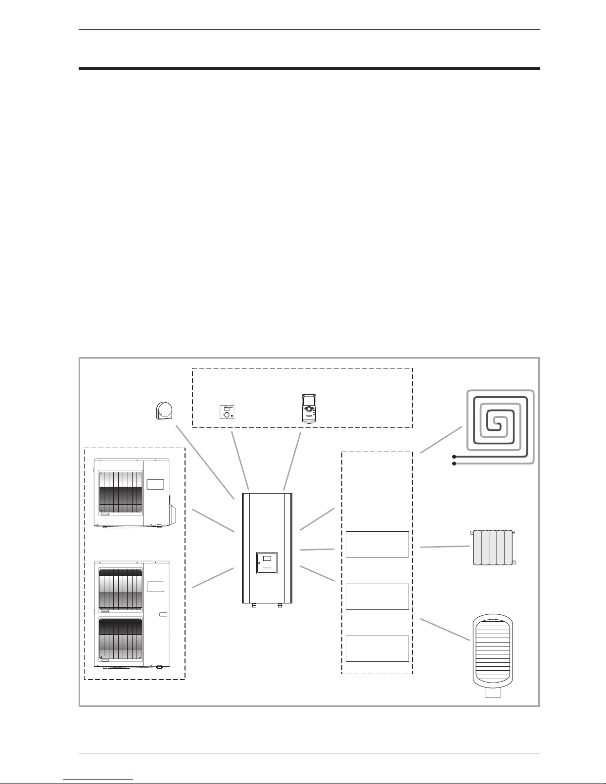
1.2.1 The outside unit
The outside unit contains the equipment for
capturing energy from the ambient air.
Your installer has placed this unit in a location that
enables it to operate in an optimum manner.
Nothing should obstruct the air circulation through
the evaporator and from the fan.
The ambient air is cooled in the outside unit in
contact with an exchanger. The water that the air
contains condenses and flows from the outdoor unit.
In cold periods, this water freezes in contact with the
exchanger and is drained away by regular defrosting
cycles. The control system automatically controls the
defrosting cycle, whose operation can lead to the
quite normal emission of steam.
1.2.2 The hydraulic unit
The hydraulic unit contains the heat pump complete
control system, in charge of controlling the heating
comfort level and the production of domestic hot
water (if a DHW tank is connected).
The hydraulic module is equipped with an electric
back-up system, which is designed to provide
additional heat during the coldest periods.
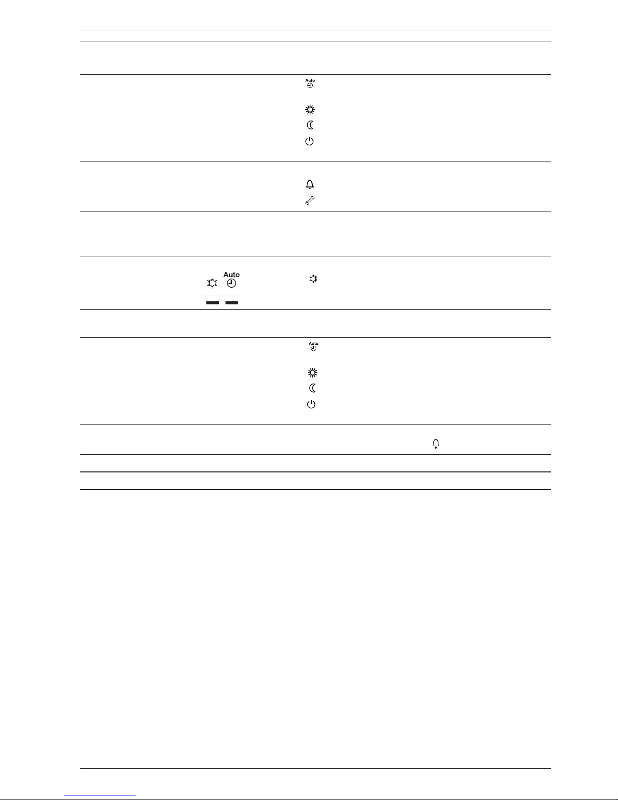
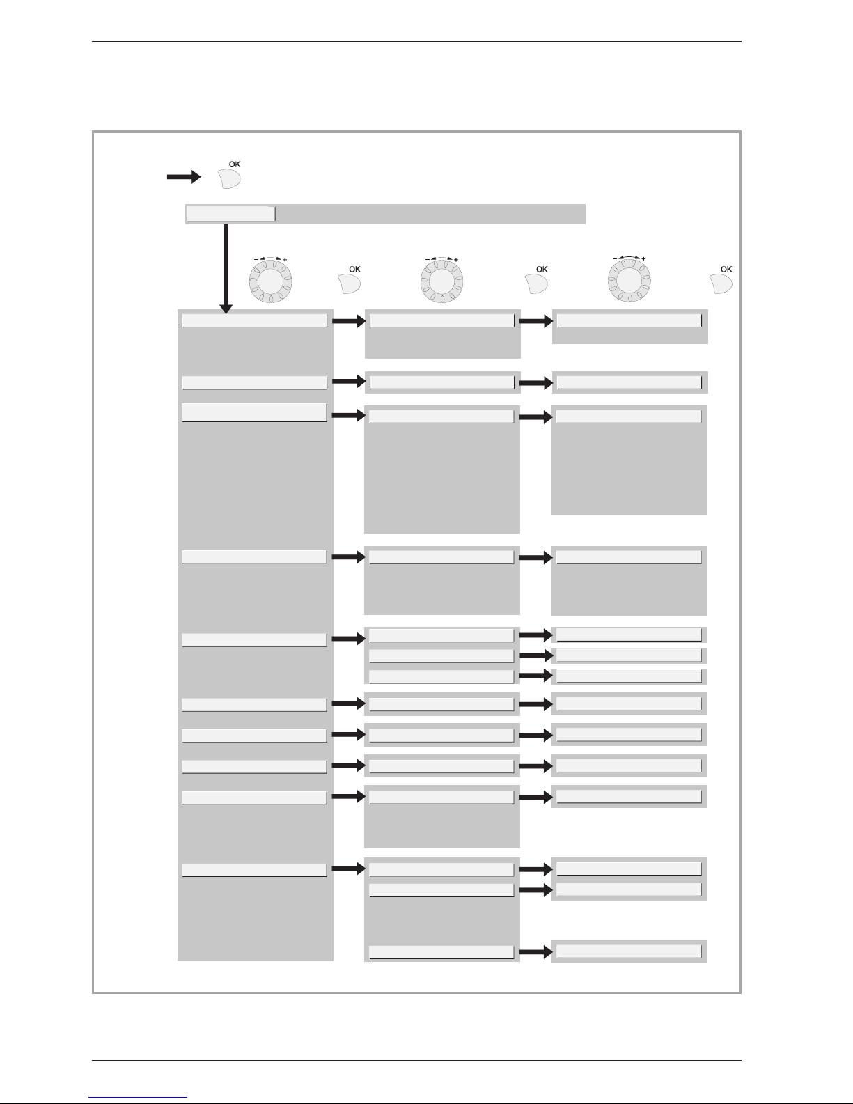
1.2.3 Control system
Your installer has carefully adjusted your installation.
Do not modify setting parameters without his
agreement. If in doubt, do not hesitate to contact him.
The control system for your heating system is
designed:
-either as a fixed flow temperature for the water (only
for low temperature radiators with thermostatic
valve controls).
-Or as a flow temperature for the water based on the
external temperature (water control) with the
installation of an ambient air sensor (option).
This second solution (water control) is the only one
usable for Floor-heating systems. It is also very
effective for thermostatically controlled radiators.
1.2.4 Floor-heating systems
•New floor-heating systems require to be initially
heated slowly to avoid any problems with cracking.
Check with your installer that this initial heating
procedure has indeed been performed before using
your heating system freely.
•To be efficient, floor-heating systems do not need to
be very hot and never should be. At most, the
systems should be warm to the touch in cold
weather.
•The great stability in a regulation system for
floor-heating systems avoids sharp differences in
temperature. However, this stability involves a
reaction time of the order of several hours, (approx
6 hours).
•Any changes to the setting must be made slowly,
leaving the installation time to react. Adjusting the
system to exaggerated setting or in an untimely
manner always results in significant temperature
fluctuations during course of the day.
•Similarly if your dwelling has a floor-heating system,
do not reduce the heating or switch it off if you will be
absent for a short period. The reheating period is
always quite long (approx 6 hours).
1.2.5 Domestic hot water (DHW)
This function is designed as an option through the
use of a DHW tank with electrical backup heating.
When the DHW production is required, the heat
pump adapts to this demand as a priority.
No space heating is produced while the domestic hot
water is being prepared.
The heat pump produces the domestic hot water,
which is then supplemented, if required, by electrical
backup heating inside the tank.
The electrical backup heating enables anti-legionella
cycles to be conducted efficiently.
4 Instruction manual “1353-EN”
Heat pump, split, single service

2Overall view of the installation
Your heat pump has been configured by your
installer. It is composed of the following main
elements:
-The outside unit is positioned, as its name
indicates, outside your dwelling and extracts
energy from the outside air.
-The hydraulic unit positioned in your boiler room,
cellar, garage or even your kitchen, transfers the
energy to the heating circuit (and the domestic hot
water).
-T h e o u t d o o r s e n s o r d e t e c t s t h e o u t s i d e
temperature.
Optional equipment:
-Room thermostat
-Remote control
Heat pumps are systems that can be connected to
any form of low temperature heat distribution
systems: the heat captured by the heat pump can
therefore be used in different ways:
-Floor-heating systems
-Radiators or warm fan coil heaters
-Domestic hot water (DHW)
Instruction manual “1353-EN” 5
Heat pump, split, single service
or
The outside unit
The hydraulic unit
Heating circuit
Radiators or
fan convectors
Heating circuit
Floor heating system
or/and
Room
thermostat
Remote
control
Control options
Options
depending
on the system
configurations
2nd circuit kit
Outdoor
sensor
DHW tank
(with electrical
back-up heating)
DHW kit
Boiler
connexion kit
Figure 1 - Overall view of the configuration of a complete installation

6 Instruction manual “1353-EN”
Heat pump, split, single service
Ref. Function -Definitions
1Selection of the DHW operating mode
(Domestic hot water)
-If the installation is fitted with a DHW tank.
-ON: Production of DHW according to the time program.
-Off: No domestic hot water heating, anti-frost function is active.
-Boost: Hold down the DHW key for 3 seconds. Immediate DHW
operation after use of the electrical back-ups until the DHW
comfort setting has been reached
2Digital display -Operating control. Readout of the current temperature, of the
heating mode and of any faults .
-View the settings
3Exit "ESC" -Quit the menu.
4Navigation and setting -Selecting the menu.
-Setting parameters.
-Adjusting the ambient temperature setpoint.
Figure 2
1
2
3
4
5
6
7
8
9
°C
10
12
13
11
User interface
Remote control (option)
Room thermostat (option)
ON
Off
3Operation of the installation
3.1 User interface

Instruction manual “1353-EN” 7
Heat pump, split, single service
5Selecting the heating mode -Heating operating according to the heating programme
(Summer/winter mode switchover is automatic).
-Constant comfort temperature.
-Constant reduced temperature.
-Stand-by mode with anti-frost protection (Provided that the
heat pump's electrical power supply is not interrupted).
6Information display -Various data (please see page 15).
-Reading error codes.
-Information concerning maintenance, special mode.
7Confirm "OK" -Input into the selected menu.
-Confirmation of the parameter settings.
-Confirmation of the adjustment to the comfort temp. setting.
8Selecting cooling mode -If the installation is fitted with the cooling kit:
-Cooling operating according to the heating programme
(Summer/winter mode switchover is automatic).
9RESET button
(Hold down the "RESET" key for 3 seconds).
-Reinitialising the parameters and cancelling error messages.
Do not use during normal operation.
10 Selecting the heating mode -Heating operating according to the heating programme
(Summer/winter mode switchover is automatic).
- Constant comfort temperature.
- Constant reduced temperature.
- Stand-by mode with anti-frost protection (Provided that the
heat pump's electrical power supply is not interrupted).
11 Digital display -Operating control. Readout of the current temperature, of the
heating mode and of any faults .
12 Control knob -Adjusting the ambient temperature setpoint
13 Occupancy key -Comfort / Reduced switchover
Ref. Function -Definitions

3.2 Appliance start up.
•The installation and 1st start up of the appliance
must be done by a qualified installer. That person
will also give you instructions on starting and
running the appliance.
•Ensure that the installation is fully filled with water
and has been correctly bled and that there is a
sufficient press u r e of 1.5 to 2 bars on the
manometer (Ref. 2, fig. 4).
•Close the installation’s main circuit breaker.
In winter, so that the compressor can be preheated,
close the installation’s main circuit breaker (outside
unit’s power supply) some hours before pressing the
on/off button.
3.3 Quick start-up
Once your installer has started your installation for
the first time:
•Engage the heat pump’s ON/OFF button.
During the regulator initialisation phase, the display
shows all the symbols and then “Data, update” and
then “State heat pump”.
•Select the “AUTO” heating mode (Fig. 5).
•Select the DHW mode (Fig. 5)
if the installation is fitted with a DHW tank with
electrical back-up heating.
•Set the current date and time (Fig. 6).
8 Instruction manual “1353-EN”
Heat pump, split, single service
Figure 3 - Opening the door
1
2
3
Xxxxxxxxxxxxxxxxxxxxxxxxxx
Figure 4 - Start-up
1 - User interface
2 - Manometer (installation
hydraulic pressure)
3 - Start/stop switch
Figure 5 - Selecting the heating mode (AUTO)
and selecting the DHW operating mode
(domestic hot water)
Figure 6 - Setting the time and the date
Press the key OK
_ _ _ _ _ _ _ _ _ _ _ _ _ _ _
Time of day and date
Operator section
Choose menu
Time and date
Press the key OK
Time of day and date
Hours / minutes
Select ligne:
Hours / minutes
or Day / Month
or Year
Press the key OK
Time of day and date
Hours / minutes
Make all
the settings
Press OK
to confirm
each setting
Press a regime key
to return to the
standard display

Instruction manual “1353-EN” 9
Heat pump, split, single service
3.4 Programming examples
Setting the time
04 8 12 16 20 24
AUTO
2
Text3
04 8 12 16 20 24
AUTO
3
04 8 12 16 20 24
AUTO
4
04 8 12 16 20 24
AUTO
1
5
04 8 12 16 20 24
AUTO
6
0 4 8 12 16 20 24
AUTO
Basic display
If the basic display is not shown,
press ESC to return to it.
Press the key OK.
Turn the knob, choose menu:
Time and date,
Press OK to confirm.
Turn the knob, select line 1:
Hours / minutes,
The hour display flashes
Press the key OK.
Turn the knob
to set the time,
The minutes display flashes
Press the key OK.
Turn the knob
to set the minutes,
The setting are recorded
Press a regime key
to return to the standard display.
Turn the knob
to make other settings
or
Keys DescriptionDisplay example
Room setpoint 1
Operator section
T
ime of day and date
Time of day and date
Hours / minutes
Time of day and date
Hours / minutes
Time of day and date
Hours / minutes
Time of day and date
Hours / minutes
Figure 7

10 Instruction manual “1353-EN”
Heat pump, split, single service
3.5 Structure of the “End user”
control menu
1
2
3
20
500
501
502
503
504
505
506
516
641
642
643
648
710
712
714
6711
7141
8410
8412
8413
8701
8702
8703
...
9037
Reduced temp... 35 °C
Consigne confort 1610
DHW
Hours / minutes
Day / Month
Year
Hours 1...24 h
Minutes 0...60 min
OEM
Specialist
Start-up
End user
Language ...English, German
Preselection
1st phase On (start)
1st phase Off (end)
2nd phase On (start)
2nd phase Off (end)
3rd phase On (start)
3rd phase Off (end)
Standard values
Mon-Sun
Mon-Fri
Sat-Sun
Monday
Tuesday
Sunday
...
Period selection
1st phase On (start)
1st phase Off (end)
Regime level
Period
Period
Period
1
2
...
8
Reduced temp... 35 °C
Temp. frost free... comfort
4 °C...temp. réduite
Comfort setting
Reduced setting
Frost free setpoint
No, Yes
Heat pump Reset
Off, On
Emergency regime
HP return temp.
HP flow temp.
Compressor modul.
Time and date
User interface
CC1 time programme
CC2 time programme
Programme 4/DHW
Holidays heating circuit 1
Holidays heating circuit 2
Heating circuit
Heating circuit
1
2
Error
Maintenance / spec. regime
Generator diagnosis
Diagnostics consumers
Off, On
External temperature
Reset ini. ext.
Reset maxi. ext. temp.
Relay output
m temp.
...
QX7
Brief
press
Basic
display
Figure 8

Instruction manual “1353-EN” 11
Heat pump, split, single service
3.6 Parametering the setting
3.6.1 General
•Only the parameters accessible to levels:
End user
are described in this document.
•The parameters accessible at level:
Initial start-up
Specialist
… are described in the document reserved for these
pro fes si ona l spe ci a li s ts. D o not m ake a ny
modifications to these parameters w ithout
advice from these professional specialists.
3.6.2 Setting parameters
With the screen on basic display
-Press the key
Once in “End user” level
-Scroll the menu list.
-Choose the desired menu.
-Scroll the function lines.
-Choose the desired line.
-Adjust the parameter
-Check the setting by pressing OK
-To return the menu, press ESC
If no setting is made for 8 minutes, the screen returns
automatically to the basic display.
Date and time
1 Hours / minutes 00:00… 23:59 1
2 Day / Month 01.01… 31.12 1
3 Year 1900… 2099 1
User interface
20 Language English, Français,
Italiano, Nederlands...
Heating time programme, circuit 1
500 Pre-selection (day / week)
Mon-Sun Mon-Fri Sat-Sun Monday Tuesday…
Mon-Sun
501 1st phase On (start) 00 : 00… - -:- - 10 min 6 : 00
502 1st phase Off (end) 00 : 00… - -:- - 10 min 22 : 00
503 2nd phase On (start) 00 : 00… - -:- - 10 min - -:- -
504 2nd phase Off (end) 00 : 00… - -:- - 10 min - -:- -
505 3rd phase On (start) 00 : 00… - -:- - 10 min - -:- -
506 3rd phase Off (end) 00 : 00… - -:- - 10 min - -:- -
516 Standard values, Circuit 1 no, yes no
Yes + OK: The standard values memorised in the regulator replace and cancel the customised heating
programmes. Your customised settings are therefore lost.
3.6.3 List of “Consumer” settings
Line Function Setting range
or display
Setting
increment
B a s i c
setting
1
2
3
End user
Brief
press
Basic
display
Day / Month Minutes 0...60 min
Time and date
User interface
CC1 time programme
...
Hours / minutes
Year
Hours 1...24 h

12 Instruction manual “1353-EN”
Heat pump, split, single service
Line Function Setting range or
display
Setting
increment
B a s i c
setting
Heating time programme, circuit 2
If the installation consists of 2 heating circuits (only with the 2nd circuit kit option)
520 Pre-selection (day / week)
Mon-Sun Mon-Fri Sat-Sun Monday Tuesday…
Mon-Sun
521 1st phase On (start) 00 : 00… - -:- - 10 min 6 : 00
522 1st phase Off (end) 00 : 00… - -:- - 10 min 22 : 00
523 2nd phase On (start) 00 : 00… - -:- - 10 min - -:- -
524 2nd phase Off (end) 00 : 00… - -:- - 10 min - -:- -
525 3rd phase On (start) 00 : 00… - -:- - 10 min - -:- -
526 3rd phase Off (end) 00 : 00… - -:- - 10 mn - -:- -
536 Standard values, Circuit 2 no, yes no
Yes + OK: The standard values memorised in the regulator replace and cancel the customised heating programmes. Your
customised settings are therefore lost.
Time programme 4 / DHW
If the installation is fitted with a tank (only with the DWH kit option)
560 Pre-selection (day / week)
Mon-Sun Mon-Fri Sat-Sun Monday Tuesday…
Mon-Sun
561 1st phase On (start) 00 : 00… - -:- - 10 min 00 : 00
562 1st phase Off (end) 00 : 00… - -:- - 10 min 05: 00
563 2nd phase On (start) 00 : 00… - -:- - 10 min - -:- -
564 2nd phase Off (end) 00 : 00… - -:- - 10 min - -:- -
565 3rd phase On (start) 00 : 00… - -:- - 10 min - -:- -
566 3rd phase Off (end) 00 : 00… - -:- - 10 min - -:- -
576 Standard values no, yes no
Yes + OK: The standard values memorised in the regulator replace and cancel the customised heating programmes. Your
customised settings are therefore lost.
Time programme 5 / Cooling
If the installation is fitted with the cooling kit (only with the cooling kit option)
600 Pre-selection (day / week)
Mon-Sun Mon-Fri Sat-Sun Monday Tuesday…
Mon-Sun
601 1st phase On (start) 00 : 00… - -:- - 10 min 6 : 00
602 1st phase Off (end) 00 : 00… - -:- - 10 min 22 : 00
603 2nd phase On (start) 00 : 00… - -:- - 10 min - -:- -
604 2nd phase Off (end) 00 : 00… - -:- - 10 min - -:- -
605 3rd phase On (start) 00 : 00… - -:- - 10 min - -:- -
606 3rd phase Off (end) 00 : 00… - -:- - 10 min - -:- -
616 Standard values no, yes no
Yes + OK: The standard values memorised in the regulator replace and cancel the customised heating programmes. Your
customised settings are therefore lost.

Instruction manual “1353-EN” 13
Heat pump, split, single service
Holidays programme, circuit 1
641 Preselection Period 1 to 8 Period 1
642 Date holidays start (Day / Month) 01.01… 31.12 1
643 Date holidays end (Day / Month) 01.01… 31.12 1
648 Heating schedule during the holidays Frost protection, Reduced F r o s t
protection
Holidays programme, circuit 2
If the installation consists of 2 heating circuits (only with the 2nd circuit kit option)
651 Preselection Period 1 to 8 Period 1
652 Date holidays start (Day / Month) 01.01… 31.12 1
653 Date holidays end (Day / Month) 01.01… 31.12 1
658 Heating schedule during the holidays Frost protection, Reduced F r o s t
protection
Heating adjustment, circuit 1
710 Comfort ambient temperature setpoint from reduced
temperature to 35°C
0,5 °C 20 °C
712 Reduced ambient temperature setpoint from frost-free temp… to
comfort temperature
0,5 °C 18 °C
714 Frost-free ambient temperature setpoint from 4°C…
to reduced temperature
0,5 °C 8 °C
Cooling adjustment circuit 1
If the installation is fitted with the cooling kit (only with the cooling kit option)
901 Operating mode Off, Automatic Off
902 Comfort ambient temperature setpoint 17...40 °C 0,5 °C 24 °C
907 Release 24h/day, Time
programme HC, Time
programme 5 / Refresh
24h/day
If the installation is fitted with a DHW tank, set the parameter 907 to "Time programme 5 / Cooling" (in order to
activate cooling only during the day and leave the DHW system to operate during the night).
Heating adjustment, Circuit 2
If the installation consists of 2 heating circuits (only with the 2nd circuit kit option)
1010 Comfort ambient temperature setpoint from reduced
temperature to 35°C
0,5 °C 20 °C
1012 Reduced ambient temperature setpoint from frost-free temp… to
comfort temperature
0,5 °C 18 °C
1014 Frost-free ambient temperature setpoint from 4°C… to reduced
temperature
0,5 °C 8 °C
DHW setting (domestic hot water) (only with the DHW kit option)
1610 Comfort setting reduced setting (line 1612)…
to 65 °C
160 °C
The backup electrical system is required to reach this level.
1612 Reduced setting 8 °C...to
comfort setting (line 1610)
140 °C
Line Function Setting range
or display
Setting
increment
B a s i c
setting

14 Instruction manual “1353-EN”
Heat pump, split, single service
Swimming pool (Only with swimming pool kit option)
2056 Generator heating setting 8... 35 °C 22 °C
Error
6711 Heat pump Reset No, yes No
Maintenance / special mode
7141 Emergency operation Off, ON Off
Off: The heat pump does not use the backup electrical heating system or the boiler connection when a fault
occurs (error 370)
ON: The heat pump uses the backup electrical system or the boiler connection when a fault occurs (error
370). In the "ON" position, the energy costs can be huge if the error is not eliminated.
Diagnostics heat generation
8410 Heat pump return temperature 0 … 140 °C
Setpoint (flow) HP 0 … 140 °C
8412 Heat pump flow temperature 0 … 140 °C
Setpoint (flow) HP 0 … 140 °C
8413 Compressor modulation 0 … 100%
Diagnostics consumers
8700 External temperature -50 .. 50 °C
8701 Minimum external temperature
Reset ? (no, yes)
-50 .. 50 °C
8702 Maximum external temperature
Reset ? (no, yes)
-50 .. 50 °C
8721 Room temperature 0 .. 50 °C
8740 Room temperature 1 0 … 50 °C 20 °C
Ambient temperature setting 1 4 … 35 °C 20
8743 Flow temperature 1 0 … 140 °C 50
Flow temperature setpoint 1 0 … 140 °C 50
8756 Cooling flow temperature 1 0 … 140 °C 0
Cooling flow temperature setpoint 1 0 … 140 °C 0
8770 Room temperature 2 0 … 50 °C 20
Ambient temperature setpoint 2 4 … 35 °C 20
8773 Flow temperature 2 0 … 140 °C 50
Flow temperature setpoint 2 0 … 140 °C 50
8830 DHW (domestic hot water) temperature 0 … 140 °C
DHW temperature setpoint 5 … 80 °C 50
8900 Swimming pool temperature 0 … 140 °C
Swimming pool temperature setpoint 0 … 80 °C 24
Line Function Setting range or
display
Setting
increment
B a s i c
setting

3.7 Information display
Various data can be displayed by pressing the info
button.
Depending on the type of unit, configuration and
operating state, some of the info lines listed below
may not appear.
-Possible error messages from the error code list.
The display shows the “Bell” symbol .
- Consult your heating technician
-Possible service messages from the maintenance
code list. The display shows the “Key” symbol .
- Consult your heating technician
-Possible special mode messages. The display
shows the “Key” symbol .
- Consult your heating technician
Various data (see below).
Designation Line
Floor drying current setpoint -
Current drying day -
Terminated drying days -
Room temperature 8721
State heat pump 8006
State supplementary source 8022
State DHW 8003
State swimming pool 8011
State heating circuit 1 8000
State cooling circuit 1 8001
State heating circuit 2 8004
External temperature 8700
Room setpoint 1 8740
Flow temperature 1
8743
Flow temp setpoint 1
Room setpoint 2 8771
Flow temperature 2
8773
Flow temp setpoint 2
DHW temperature 8830
Heat pump return temperature
8410
Setpoint HP (flow)
Heat pump flow temperature
8412
Setpoint HP (flow)
Swimming pool temperature
8900
Swimming pool temperature setpoint
3.8 Details
If the electrical power supply has been cut off while
the heat pump is operating (electrical power failure
or unprogrammed pressing of the on/off switch on
the hydraulic unit) the display will show error 370
when the appliance restarts. Do not be concerned,
the communication between the outdoor and
hydraulic units will re-establish itself in a few
moments.
3.9 Operation of the DHW system
T h e k e y ( f i g u r e 1 0 )
enables you to switch the
D H W ( d o m e s t i c h o t
water) mode on and off if
the installation is fitted
with a DHW tank with
e l e c t r i c a l b a c k - u p
heating. The selection is
shown by a bar, which
appears under the
corresponding symbol.
Press the info key to
obtain the details on the
D H W ( t e m p e r a t u r e
setting operation).
3.10 Selecting cooling mode
If the installation is fitted
with the cooling kit.
Th e ke y (f ig ur e 11 )
enables you to switch the
cooling mode on and off.
Instruction manual “1353-EN” 15
Heat pump, split, single service
...
Brief
press Details of any error
Operating values
Figure 9 - Information key
Figure 10 - Selecting the
DHW operating mode
(domestic hot water)
Figure 11 -
Selecting cooling mode

16 Instruction manual “1353-EN”
Heat pump, split, single service
3.11 Configuring remote control (option)
Installation equipped with a remote control.
During commissioning, after an initialisation period
of approx. 3 minutes, the user’s language must be
set:
-Press the key
-Choose menu “Bedieneinheit”
-Choose language “Sprache” English.
4Maintenance
In order to insure your appliance operates correctly
for many years, the maintenance operations
described below are required at the start of each
heating season. Generally, these are performed as
part of a service contract.
4.1 Checking that the floor system is
full
The pressure in the floor system when it is cold and
when it has stopped must be 1.5 bars.
If filling and re-pressurisation are required, check
what type of fluid has been used initially.
If in any doubt, contact your installer.
Warning, if frequent filling is required, have the
installation’s sealing checked.
4.2 Checking the outside unit
Dust off the exchanger if necessary, being careful not
to damage the fins.
Check that there is nothing obstructing the passage
of air.
4.3 Checking the refrigeration circuit
When the coolant fluid charge is in excess of 2kg
(095, 112, 128, 140,155 and 160 models), it is
compulsory to have an approved after sales service
check the refrigeration circuit every year. Consult
your heating technician.
This appliance is marked with this symbol. This means that electrical and electronic products shall not be mixed
with general household waste.
European Community countries(*), Norway, Iceland and Liechtenstein should have a dedicated collection sys-
tem for these products.
Do not try to dismantle the system yourself as this could have harmful effects on your health and on the envi-
ronment.
The dismantling and treatment of refrigerant, oil and other parts must be done by a qualified installer in accor-
dance with relevant local and national regulations.
This appliance must be treated at a specialized treatment facility for re-use, recycling and other forms of reco-
very and shall not be disposed of in the municipal waste stream.
Please contact the installer or local authority for more information.
* subject to the national law of each member state
Table of contents
Popular Heating System manuals by other brands

Aspira
Aspira ECOCOMFORT RF Series user manual

Airia
Airia Lifebreath RNC5-ES Homeowner's guide

Viessmann
Viessmann Vitocrossal 300 CT3 SERIES Safety and installation requirements

Thermo Scientific
Thermo Scientific 2122 operating manual

White Rodgers
White Rodgers 3L09 installation instructions

Vasco
Vasco Energy plus Installation, use and maintenance instructions