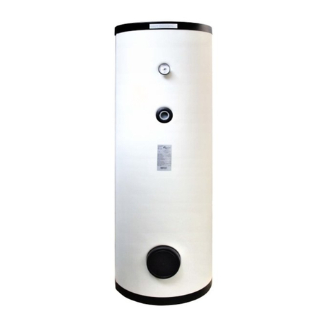
Stuart Turner Aquaboost iBoost +200 CAT 5 Guide

Installation, Operation & Maintenance
Instructions
Please leave this instruction booklet with the home owner as it contains
important guarantee, maintenance and safety information
Read this manual carefully before commencing installation.
This manual covers the following products:
CE compliant product
iBoost +200
Pt. No. 46712
iBoost +200 CAT 5
Pt. No. 46714
Please note images are representative only and
may not portray your model

- 2 -
Cont ...
PRODUCT DESCRIPTION
iBoost +200
Additional water storage tank consisting of fill valve, 200 litre water storage and coupling
for system integration to an iBoost 200. The design of the tank incorporates an AF air gap
for fluid isolation (BS EN 1717).
iBoost +200 CAT 5
Additional water storage tank consisting of fill valve, 200 litre water storage and coupling
for system integration to an iBoost 200 CAT 5. The design of the tank incorporates an AB
air gap for fluid isolation (BS EN 1717).
APPLICATION
The Aquaboost iBoost +200 is designed to meet the demand of pressurised systems in
larger domestic applications where the existing mains water supply is insufficient. Inlet
pressures to the tank and ambient temperatures must not exceed the values
given in the technical specifications.
zThis appliance must not be used for any other
application without the written consent of Stuart
Turner Limited.
zThis appliance can be used by children
aged from 8 years and above and persons with
reduced physical, sensory or mental capabilities
or lack of experience and knowledge if they have
been given supervision or instruction concerning
use of the appliance in a safe way and understand
the hazards involved. Children shall not play with
the appliance. Cleaning and user maintenance
shall not be made by children without supervision.
zChildren should be supervised to ensure that they
do not play with the appliance.
zThis product should not be used for the supply of
water to more than one dwelling (house,
apartment, flat).
Please read installation details carefully as they are intended to ensure this
product provides long, trouble free service. Failure to install the unit in
accordance with the installation instructions will lead to invalidation of the
warranty.
STORAGE
If this product is not to be installed immediately on receipt, ensure that it is stored in a dry,
frost and vibration free location in its original packaging.

- 3 -
Cont ...
CONTENTS Page
Checklist ........................................................4
Important Facts - read before commencing installation ...................5
Location ........................................................6
Key Features ....................................................7
Installation ......................................................8
Commissioning ...................................................14
Maintenance .....................................................15
Technical Specication .............................................17
Trouble Shooting .................................................18
Guarantee .......................................................19

- 4 -
Cont ...
CHECKLIST
Note: Item B supplied loose - this will require fitting to the pump outlet. Tighten to torque
4/5 Nm.
Your product may vary slightly from the picture above.
Item Description Qty Item Description Qty
iBoost +200 1 Jubilee clip 2
Retaining strap 1 Hose connector 2
M6 screw 1 Tank connector 2
Hose cover 1 Instruction book 1
Hose 1 Installation book 1
‘O’-ring (52 mm ID) 2
A
E
C
B
D
F
G
H
I
J
K
Fig. 1
IMPORTANT: With the appliance removed from
its packaging check for any damage prior to
installation. If any damage is found contact
Stuart Turner Ltd within 24 hours of receipt.
A
D
C
E
F
B
G
H
I
J
K

- 5 -
Cont ...
1 IMPORTANT FACTS: READ BEFORE COMMENCING INSTALLATION
A. Water storage capacity.
1.11 The iBoost +200 has a usable water volume of approximately 200 litres; the
length of time the iBoost delivers water will be dependent on the usage and refill
rates.
B. Water temperature
This unit is designed to offer extended water storeage and not exceed the following
values:
1.12 The maximum allowable water temperature is 23 oC (see Section 7.13).
1.13 The minimum allowable water temperature is 4 oC.
C. Pipework - General
1.14 Secure pipework: Ensure pipework to and from pump is independently
supported & clipped to prevent forces being transferred to inlet and outlet
branches of pump. Do not secure pipework to the iBoost, this will cause
damage and possible leakage.
1.15 Flux: Solder joints must be completed and flux residues removed prior to iBoost
installation (flux damage will void any warranty).
1.16 Pipework design: Care should be taken in the design of pipework runs to
minimize the risk of air locks e.g. use drawn bends rather than 90obends.
1.17 DO NOT introduce solder flux to flexible hose, tank, pump or any parts
manufactured from plastic.
1.18 DO NOT allow contact with oil or cellulose based paints, paint thinners or
strippers, acid based descalents or aggressive cleaning agents.
1.19 DO NOT bend the flexible hose beyond 30o. It must be installed as
straight as possible.
D. Plumbing Installation Regulations
1.20 The plumbing installation must comply with the current water and building
regulations.
1.21 The plumbing installation must be installed by a qualified person.

- 6 -
Cont ...
2 LOCATION - GENERAL
2.11 Access: The iBoost +200 must be easily accessible.
2.12 Protection: The iBoost must be located in a dry, frost free area.
The iBoost must not be installed in a loft space.
2.13 Water retention: Site the iBoost in a location where in the unlikely
event of a water leak, any spillage is contained or routed to avoid
electrics or areas sensitive to water damage.
2.14 Supply inlet pressure: The water supply inlet pressure must be lower than
7 bar; lower supply inlet pressures will reduce the tank fill rate.
2.15 Ambient temperature: The iBoost must be sited in a location where the
ambient temperature does not exceed 30 oC (see Section 7.11 - Water
Quality).
2.16 Preferred iBoost location: The preferred iBoost +200 location is immediately
adjacent to the iBoost unit on a smooth level floor of sufficient strength to
support the combined filled weight.
Only one iBoost +200 supplementary tank can be connected to
an iBoost 200 master unit.
Ensure there is sufficient room above the iBoost to allow the removal and
servicing of the internal float valve if needed, typically 350 mm.

- 7 -
3 KEY FEATURES
iBoost +200
iBoost +200 CAT 5
Label
Part No & Serial No
Overflow
Tank
Tank access cover
Mains water connection
Fig. 2
Retaining strap
Cover retaining screw
location
Fig. 3
Drain valve
Weir aperture

- 8 -
4 INSTALLATION
4.11 Mains water connection to iBoost: The iBoost +200 is to be permanently
connected to the mains water supply using rigid pipe or suitably sized and rated
flexible hose to comply with current building and plumbing regulations.
The water tank fill valve has a G ½ male threaded fitting; a suitable 90oelbow
type fitting must be used. When tightening ensure the fill valve within the tank
is not rotated. If the valve is rotated it may not function correctly with the risk of
flooding.

Ensure there is a demountable joint in the pipe to allow the removal of the iBoost
if needed (see Fig. 15).
4.12 Water outlet pipework:
The iBoost +200 is supplied with a kit for connecting it to an iBoost 200 unit,
side to side.
If a greater distance between the units is required then a longer hose will need to
be sourced.
4.13 Connection to overflow/warning pipe: The overflow fitting is designed to use
1 ¼ " (35 mm OD) plastic waste pipe. Ensure there is a demountable joint in the
pipe to allow the removal of the iBoost if needed (see Fig. 15). The overflow must
be free to vent to atmosphere either via a tundish or a dedicated external pipe.
The overflow for the +200 unit is to be kept separate from the existing iBoost 200
unit’s overflow.
4.14 The iBoost is intended to be installed as a freestanding unit with its back
to a wall.
All the services are connected to the iBoost via a plumbing access window at the
back of the unit, the installation is conducted in 3 simple steps.
Prior to installation remove the screw on the top of the unit and pull the corner of
the front cover to remove it and retain them in a safe place.
Step 1 Preparation:
a) If connecting to an already installed iBoost 200 unit, then drain the water out
of the tank. It needs to be empty in order to connect the +200 unit to it.
b) The kit provided is for side connection only, back connection is possible
with additional fittings and longer hose (not supplied). The supplied hose
provides a maximum gap between the units of approximately 262 mm (from
tank to tank). Measure the gap and check there is enough space to fit the
secondary unit in place.
262
536
Fig. 4
iBoost
+200 unit
iBoost
200 unit

- 9 -
Cont ...
c) First step is to decide where your preferred connection should be, either the
side or the rear of the tanks then mark the centre point location on both units
(iBoost +200 and iBoost 200).
Note: Later models will have pre-marked centres on the tank.
Step 2 Fitting of the tank connector:
a) Mark 2 circles approximately on both tanks using the previous location as
their centres. One for the hole at 65 mm diameter and the other to add fitting
at 89 mm diameter.
b) Cut a hole in both tanks using a 65 mm diameter hole cutter using the centre
points marked previously. Take care not to allow debris to fall into the tank
and keep cut edge free from burrs and hole as near to size as possible.
c) Straighten the wire holder and pass through body as shown. Then, whilst
holding the wire in one hand, manipulate the flanged end of the body into the
hole. This is easily done if one lug is inserted at a time, turning the body from
left to right.
FRONT
BACK
65
100
BACK
260
65
Fig. 5 Side connection Back connection (not supplied)
O89
O65
Fig. 6
Hole to be cut
Fig. 7
Body
Wire holder
OR

- 10 -
Cont ...
d) Whilst taking care not to drop/lose the wire holder inside the tank, thread the
split washer onto the wire holder and then with the aid of the split, insert the
washer into the hole in a spiral manner. Place washer into the body and
against the flange.
e) Thread the rubber washer followed by the ‘O’-ring onto the wire holder
and push them through the hole and onto the body until they are against the
copper washer.
Note: The ‘O’-ring is to help position the flange in the hole due to material
thickness in order to aid sealing.
f) The whole assembly can now be pulled into position by pulling gently on the
wire holder.
Note: Take care to see that the body is in the centre of the hole, using the
outer marked circle as a guide.
g) Holding the fitting firmly in position, add the second rubber washer and brass
washer. Screw the nut onto the end of the thread. Apply jointing compound
(not supplied) to thread before screwing up.
Note: Before tightening the joint make sure the connection is within the outer
guide circle previously marked and then make the joint as tight as possible.
Fig. 8

Hole in tank
Split washer
Fig. 9

Rubber washer
Wire holder
O’-ring
Fig. 10
Brass washer
Wire holder
Nut
Body in tank
Rubber washer

- 11 -
h) Remove the wire holder from the tank by pulling it through. DO NOT allow
for it to fall inside. Repeat steps C - H to fit the second flange in the other
tank.
Step 3 Connecting the tanks:
a) Apply appropriate sealer such as threadlock or PTFE tape to each hose
connector and screw one into each tank connector.
b) Position the paper installation template on the wall alongside the existing unit
where the iBoost +200 is to be installed, approximately 262 mm away from
existing tank. Ensure the ‘floor level’ of the template is level and resting on
the surface the iBoost is to be mounted on (Fig. 13).
Fig. 11
Assembled connector
Wire holder
Fig. 12
Tank connector
Hose connector
InstallationTemplate
140
100
480
320
600
100
262
Fig. 13
Mains water supply
Non-pumped water supply
Overflow
Floor
All dimensions in mm
Pumped water supply
(connection only for
iBosot +200)
Tundish
External
overflow
Template
Previously installed
iBoost 200 unit

- 12 -
Cont ...
c) Run the mains water and overflow to the template positions and make the
pipe length as detailed in Fig. 14).
d) Slide the iBoost +200 in front of the services leaving approximately 20 mm
gap between the iBoost and the wall behind. Connect the services using
isolation valves and demountable fittings (push-fit or compression) were
shown in Fig. 15. The positioning of these fittings allow the iBoost to be
removed without cutting pipes or draining the system.
Fig. 14
Mains water supply
Pumped water supply
(connection only for iBoost 200)
Overflow
Isolating valve
Non-pumped water supply
B
A
Length of pipework from wall* mm
A Overflow 490
B Mains water supply 500
*Lengths are dependent on fittings used
Fig. 15
Overflow
Non-pumped
water supply
Mains water
supply
Pumped water supply
(connection only for
iBoost 200)
Demountable
fittings

- 13 -
Cont ...
e) Fix the retaining strap to
the top of the iBoost +200
using the M6 screw
provided.The free end of
the strap must be secured
to suitable wall using
suitable fastening system.
f) Push one end of the hose
onto one of the hose
connectors and fix into
position using the jubilee
clip.
g) Feed the other jubilee clip
onto the hose and
manipulate the hose onto
the other hose connector.
With the jubilee clip into
position, tighten to secure
hose.
h) Spllit the hose cover apart
at the join and push over
the hose.
4.15 It is recommended that at least one drinking water tap is connected into the un-
pumped mains water supply (typically a kitchen sink), so the water supply is
maintained in the event of a failure of the pumped supply.
Fig. 16
Secure to wall using
suitable fastener (not
supplied)
Retaining strap
M6 screw
Fig. 17
iBoost
+200 unit
iBoost
200 unit
Jubilee clip
Hose Hose
connector
Fig. 18
iBoost
+200 unit
iBoost
200 unit
Jubilee clip
Hose
Fig. 19
Hose
cover

- 14 -
Cont ...
5 COMMISSIONING / STARTING
6.11 System Flushing
The pipework system should be flushed out prior to the iBoost
being connected to ensure any contaminants/chemical residues
and foreign bodies are removed from elsewhere in the system.
Fill the system and check for leaks, refer back to the iBoost 200
manual for priming and starting of the pump.
6.12 Water Supply: Always ensure that water supply is adequate to meet the
demand.
6.13 For Further Technical Support: Phone the Stuart Turner PumpAssist team
on +44 (0) 800 31 969 80. Our staff are trained to help and advise you over the
phone.

- 15 -
Cont ...
6 MAINTENANCE
6.11 Water quality: The iBoost has been manufactured to the highest standard from
WRAS approved materials.
As with any stored volume of water; in order to ensure that the water remains
fit for use the water temperature needs to remain below 20 oC. The quality of
stored water will deteriorate with time and temperature. Bacterial growth is
dependent on the water temperature, growth rates will be higher when the
conditions are warm.
If the water remains unused for long periods of time, the tank should be drained
and flushed through. The tank should be cleaned on an annual basis to protect
against bacterial growth. If the iBoost is installed in a rental property, it must be
maintained in line with current Health & Safety regulations.
6.12 The tank can be drained by isolating the mains water supply to the fill valve and
using the pump to pump the water out of the tank.
6.13 Front cover cleaning: The front cover is made from acrylic capped ABS, it
must only be cleaned with warm soapy water or mild detergent.
Do not use abrasive cleaners. The front cover is supplied with clear protective
film in place, this can be removed by lifting at the edge.
Fig. 20
Drain valve
Do not
overtighten

- 16 -
Cont ...
6.14 Float fill valve: The float level is factory set but if in time the water level in the
tank is found to be too high, the level can be adjusted by moving the float
assembly on the arm of the fill valve down (see Fig. 21). Access the float fill
valve by removing the lid of the tank (see Section 3 - Key Features). This is done
by loosening the M6 retaining screw and sliding the float assembly down
(reduce dimension X), the M6 screw is then retightened ensuring the float is still
in line with the arm.
Fig. 21
M6 retaining screw
‘X’

- 17 -
7 TECHNICAL SPECIFICATION
Stuart Turner reserve the right to amend the specification without notice.
Pump Model iBoost +200
46712
iBoost +200 CAT 5
46714
General Guarantee 3 years
WRAS approval Approved material -
Features Fluid risk compatibility CAT 3, CAT 4 CAT 5
Air gap Type AF Type AB
Performance Maximum inlet pressure (tank fill valve) 7 bar (700 kPa)
Maximum static outlet head 15 metres
Ambient air temperature (Min - Max) 4 oC - 30 oC
Water tank Nominal size 220 litres
Usable capacity 200 litres
Fill rate 20 l/min*
Connections Cold water inlet G ½ male
Overflow (compression fitting) G 1 ¼ G ¾
Materials Break tank Polyethylene
Front panel Acrylic capped ABS
Physical Depth 529 mm
Width 536 mm
Height 1504 mm
Empty weight 35 Kg
Filled weight 235 Kg

- 18 -
Cont ...
8 TROUBLE SHOOTING GUIDE
8.11 Environment Protection: Your appliance contains valuable materials which
can be recovered or recycled.
At the end of the products’ useful life, please leave it at an appropriate local civic
waste collection point.

- 19 -
9 THE AQUABOOST iBOOST F200 / V200 GUARANTEE
Congratulations on purchasing a Stuart Turner product.
We are confident this product will provide many years of trouble free service as all
our products are manufactured to the very highest standard.
The Aquaboost iBoost is guaranteed to be free from defects in materials or
workmanship for 3 years from the date of purchase.
Within the guarantee period we will repair, free of charge, any defects in the product
resulting from faults in material or workmanship, repairing or exchanging the whole
unit as we may reasonably decide.
Not covered by this guarantee: Damage arising from incorrect installation, improper
use, unauthorised repair, normal wear and tear and defects which have a negligible
effect on the value or operation of the product.
Reasonable evidence must be supplied that the product has been purchased within
the guarantee term prior to the date of claim (such as proof of purchase or the
product serial number).
This guarantee is in addition to your statutory rights as a consumer. If you are in any
doubt as to these rights, please contact your local Trading Standards Department.
In the event of a claim please telephone ‘PumpAssist’ with proof of purchase and
product serial number.
+44 (0) 800 31 969 80
You should obtain appropriate insurance cover for any loss or damage which is not
covered by Stuart Turner Ltd in this provision.
Please record here for your records.
TYPE NO. SERIAL NO. DATE PURCHASED

Stuart Turner Ltd, Henley-on-Thames, Oxfordshire RG9 2AD ENGLAND
Tel: +44 (0) 1491 572655, Fax: +44 (0) 1491 573704
[email protected] www.stuart-turner.co.uk
Installers – Register with Stuart Turner and move up to Approved Installer status
We receive thousands of enquiries every month from people seeking a Stuart Turner installer and by registering your details with
us, we can offer consumers the opportunity to quickly locate an installer in their area.
Registration is free - simply click on the ‘register as an installer’ link on our homepage at www.stuart-
turner.co.uk and complete a short form which will enable visitors to find your contact details on our web
site ‘installer finder’. Alternatively use your smartphone to scan this QR code and go straight to the form.
We’ll do the rest!
In addition we will ensure you receive advance notice on all new product launches and access to any special
offers or promotions.
Following initial registration, Stuart Turner offers a professional training programme, enabling you to achieve Approved Installer
status and opening the door to a range of additional benefits.
Contact approvedinstaller@stuart-turner.co.uk for further details.
Issue No. 2918/1-01 Pt. No. 20702
This manual suits for next models
5
Table of contents
Other Stuart Turner Water Heater manuals
Popular Water Heater manuals by other brands

STIEBEL ELTRON
STIEBEL ELTRON SN 5 S Operating and installation instructions

Webasto
Webasto Thermo Top C installation instructions

andrews
andrews 24/39 Installation and service manual

JENFORT
JENFORT JH Series Installation and operation manual

Eccotemp
Eccotemp EL5 manual

GSW
GSW POWER VENTED GAS FIRED WATER HEATER Installation and operating instructions