Studio Technologies 232 User manual

Copyright © 2021 by Studio Technologies, Inc., all rights reserved
studio-tech.com
User Guide
Issue 5, October 2021
This User Guide is applicable for serial numbers
M232-00151 and later with main firmware version 3.02 and later
and STcontroller software application version 3.05.00 and later.
50684-1021 Issue 5
Model 232 Announcer’s Console

This page intentionally left blank.

Model 232 User Guide Issue 5, October 2021
Studio Technologies, Inc. Page 3
MODEL 232
ANNOUNCER’S CONSOLE
Table of Contents
Revision History ............................................................................. 4
Introduction ..................................................................................... 5
Getting Started ................................................................................ 8
Dante Configuration ....................................................................... 12
Model 232 Configuration ................................................................ 14
Operation ........................................................................................ 23
Technical Notes .............................................................................. 31
Specifications ................................................................................. 39
Appendix A: STcontroller Default Configuration Values .................. 41
Appendix B: 3-Pin Header Connector Details ................................ 42
Appendix C: Block Diagram ........................................................... 43

Issue 5, October 2021 Model 232 User Guide
Page 4 Studio Technologies, Inc.
MODEL 232
ANNOUNCER’S CONSOLE
Revision History
Issue 5, October 2021:
• Documents change to Dante Aux Output operation when Hot Mic is selected.
Issue 4, May 2021:
• Documents new analog microphone input limiter function.
• Documents revised configuration name from LED Intensity to LED Intensity and Action.
• Documents two LED Intensity and Action modes.
Issue 3, October 2020:
• Revises text to reflect Audinate’s Inclusive Language Guidelines. The word “master,” in
reference to Dante® clocking, has been changed to “Leader.”
Issue 2, September 2020:
• Documents changes to Main 1 and Main 2 inputs and associated headphone monitoring.
• Documents addition of Sidetone Channel Routing feature.
• Adds technical note regarding level attenuation in Dante Aux and Talkback transmitter (output)
channels when Analog Mic Output is configured for Switched.
Issue 1, August 2020:
• Initial release.
Model 232 User Guide Issue 5, October 2021
Studio Technologies, Inc. Page 5
MODEL 232
ANNOUNCER’S CONSOLE
Introduction
The Model 232 Announcer’s Console provides
a combination of high-performance audio with
an extensive set of user features and configu-
rable resources. The unit is intended for use
in demanding broadcast sports, eSports, live
event, entertainment, and streaming broadcast
applications. With a few simple connections
the Model 232 can provide one on-air talent
with all the resources they need to support a
wide range of applications. The compact, rug-
ged steel enclosure is intended for tabletop
use, small enough for use “court-side” or in
a crowded booth, yet flexible enough for re-
mote production deployment. The Model 232
supports Dante® audio-over-Ethernet digital
media technology with AES67 compatibility for
integration into contemporary applications.
The Model 232 can integrate directly into
both Dante audio-over-Ethernet and standard
analog audio environments. With just a Power-
over-Ethernet (PoE) Gigabit network connec-
tion, a microphone, and a pair of headphones
a complete broadcast on-air position can be
created. With the addition of a second Ether-
net connection Redundant Dante can be sup-
ported. And by using the Model 232’s analog
microphone output a connection to a micro-
phone-level input on an associated remote I/O
interface or audio console can be supported.
With six Dante audio inputs and an integrated
sidetone function, users can easily create their
desired headphone audio mix. They’ll enjoy
clear and “click-free” monaural or stereo audio
that can only help their on-air performance.
Two independent Dante talkback channels
allow users to communicate with a variety
of support personnel. Among the range of
operating capabilities includes the ability to
create talent cue (IFB) channels. This was
specifically included for REMI/At-Home ap-
plications. Provision has been made such that
a technician can “customize” the Model 232’s
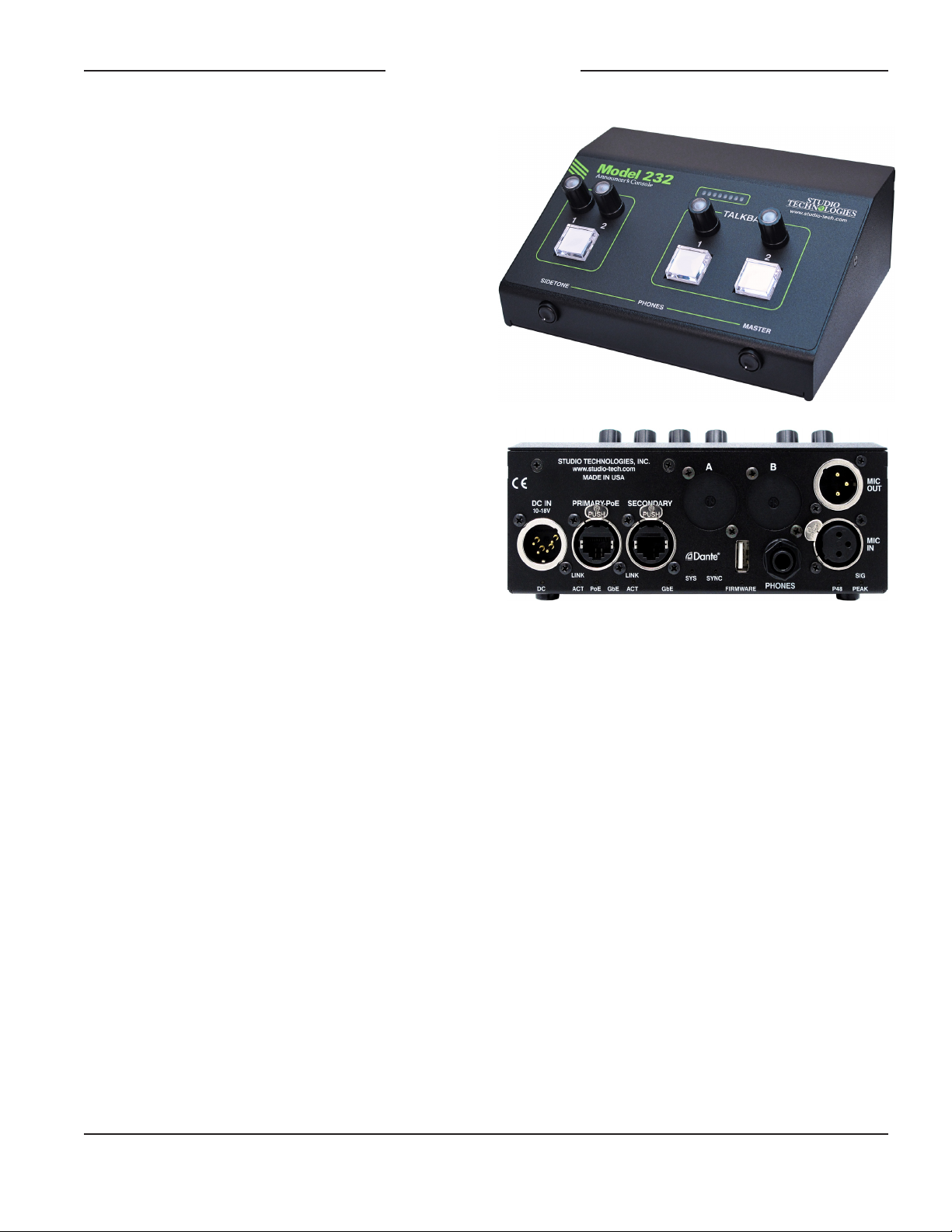
Figure 1. Model 232 Announcer’s Console front and
back views
hardware. Option kits, purchased separately,
can be added to support functions such as
multi-pin headset connectors, remote control
inputs, and a low-voltage, low-current DC tally
output.
The Model 232 was designed to meet two main
goals: supporting great audio quality and pro-
viding an extensive set of configurable features.
Using the latest in audio integrated circuits and
advanced 32-bit audio processing, the unit’s
audio performance should meet or exceed that
of any audio console, standalone microphone
preamplifier, remote I/O interface, or outboard
A/D or D/A converter. With over 40 years of
professional audio experience, Studio Technolo-
gies takes audio performance seriously! And
while providing excellent technical specifica-
tions is a “must,” a device also has to “sound”
good before we feel its design is complete.

Issue 5, October 2021 Model 232 User Guide
Page 6 Studio Technologies, Inc.
MODEL 232
ANNOUNCER’S CONSOLE
The amount of flexibility provided in the Model
232 allows it to meet the needs of virtually all
on-air announcer applications. And using the
Studio Technologies’ STcontroller software ap-
plication makes “customizing” the operation of
a Model 232 fast and simple. The unit’s ability
to handle both day-to-day and specialized situ-
ations makes it a unique product in the mar-
ket. For example, the pushbutton switches and
rotary encoders can be independently con-
figured with multiple choices that range from
simple to quite advanced. If a Model 232 can’t
seem to be configured to meet an application’s
goals please contact Studio Technologies’
technical support for an application review.
The Model 232 is part of a three-product fam-
ily that differ only in the number of talkback
channels provided. The Model 232 provides
two talkback channels, while the Model 234
provides four and the Model 236 provides six.
The Model 232, as with the other two models,
has a compact enclosure with overall dimen-
sions of 6.5 inches wide (16.5 cm), 2.9 inches
high (7.4 cm), and 4.9 inches deep (12.5 cm).
Weighing 2.1 pounds (0.95 kg), the enclo-
sure is made of steel to provide some “heft”
to minimize the chance of inadvertent move-
ment. The Model 232’s main, secondary, and
FPGA (programmable logic) firmware can be
updated using the USB port on the back of the
unit; the Dante firmware can be updated via
an Ethernet connection.
Setup, Configuration, and
Operation
Set up, configuration, and operation of the
Model 232 is simple. The unit includes two
Neutrik etherCON RJ45 connectors which
allow interfacing with single or redundant
Gigabit Ethernet networks. The primary net-
work connection can provide power to the unit
using a port on a Power-over-Ethernet (PoE)
network switch. Model 232’s power can also
be supplied from a 12 volt DC source that is
connected using a 4-pin XLR connector. A
broadcast headset or handheld (“stick”) micro-
phone can be directly connected to the unit’s
3-pin female XLR microphone input connector.
The input is compatible with dynamic or con-
denser microphones. A P48 phantom power
source allows support for a wide range of con-
denser microphones. A 3-pin male XLR con-
nector provides an analog microphone output
for integration with inputs on related devices.
A configuration choice allows this output to be
active all the time (hot mic operation) or muted
or unmuted following the main output function.
A pair of stereo headphones, the headphone
connection from a stereo or monaural head-
set, or even earbuds can be connected to the
Model 232’s headphone output jack.
Audio signals are routed to and from the Model
232 using the Dante Controller software ap-
plication. This is available, free of charge, from
Audinate®, the creators of Dante. All Model
232 operating features are configured using
the Studio Technologies’ STcontroller software
application. The extensive set of parameters
allows the unit’s functions to be tailored to
meet the needs of many, many applications.
STcontroller is available at no charge from
the Studio Technologies’ website. Versions
are available that are compatible with the
Windows® and macOS® operating systems.
STcontroller is a fast and simple means of con-
figuring, revising, saving, and loading a unit’s
operating parameters.
The Model 232’s front panel includes four rota-
ry controls (encoders) which are used to adjust
the level of the Dante input signal sources as
they create an audio mix that is fed to both the
analog and Dante digital headphone outputs.
Using RGB (red-green-blue) LEDs, each rotary
encoder is illuminated and can display whether
or not signal is present on their associated au-
dio input channels. Two additional rotary con-
trols allow adjustment of sidetone level and the
overall level of the analog headphone output.

Model 232 User Guide Issue 5, October 2021
Studio Technologies, Inc. Page 7
MODEL 232
ANNOUNCER’S CONSOLE
Three pushbutton switches allow the user to
control the status of the main outputs (digital
and analog) as well as the two talkback func-
tions. Extensive configuration choices allow
the operation of the pushbutton switches and
associated output channels to be optimized to
meet the needs of specific applications. For
example, the talkback functions can be inde-
pendently configured for talkback, talent cue-
ing (IFB), call signal (20 kHz tone), and other
related actions.
The Model 232’s one main and two talkback
pushbutton switches are illuminated to display
their operating status. For performance confir-
mation an integrated sidetone function allows
audio coming from the headset’s microphone
to be returned to the headset output.
Audio Quality
The Model 232’s audio performance is com-
pletely “pro.” A low-noise, wide dynamic-
range microphone preamplifier ensures that
microphone audio quality is preserved while
minimizes the chance of signal overload. The
gain of the microphone preamplifier can be
adjusted over a range of 20 to 65 dB in 1-
dB steps. A digitally controlled analog limiter
function allows the signal level to be automati-
cally adjusted to reduce the chance of signal
overload. A setting in STcontroller allows the
limiter function to be enabled or disabled as
desired. The limiter function applies only to
signals that are connected to the analog mi-
crophone input.
The output of the microphone preamplifier
is routed to an analog-to-digital conversion
(ADC) section that supports sampling rates
of 48 and 96 kHz. The audio signal, now in
the digital domain, routes through a 32-bit
microprocessor and associated programma-
ble logic and then on to the Dante interface
section where it is packetized and prepared
for transport over Ethernet. Six Dante trans-
mitter (output) channels are provided: one
main, one aux, two talkback, and two head-
phone monitor output channels.
Audio input signals arrive into the Model 232
by way of seven Dante receiver (input) chan-
nels and pass into the Model 232’s 32-bit logic
circuitry. Four channels are associated with
the main section, two are used for the talkback
listen sources, and one can serve as an alter-
nate microphone audio source. In addition to
being used for typical headphone monitoring,
the audio input associated with each talkback
channel can be used as part of a talent cue
(IFB) function. All channel routing, headphone
level control, signal detection, and sidetone
functions are performed within the digital do-
main. This preserves audio quality, enhances
performance, and provides flexibility, allow-
ing precise level control and mixing as well as
eliminating the need for analog audio signals
to pass through passive level controls (poten-
tiometers). The audio signals destined for the
analog headphone output are sent to a high-
performance 2-channel digital-to-analog con-
verter and then on to robust driver circuitry.
Dante Audio-over-Ethernet
Audio data is sent to and received from the
Model 232 using Dante audio-over-Ethernet
media networking technology. As a Dante-
compliant device, the Model 232’s six Dante
transmitter (output) channels and seven Dante
receiver (input) channels can be assigned
(routed or “subscribed”) using the Dante Con-
troller software application. To minimize the
chance of a flow limitation, the Model 232’s
Dante transmitter and receiver channels sup-
port 32 Dante flows, 16 in each direction.
The digital audio’s bit depth is up to 32 with a
sample rate of 48 or 96 kHz. Bi-color LEDs,
located on the unit’s back panel, provide status
indications related to the Ethernet network and
Dante interface performance.
The Model 232 is compliant with the AES67
interoperability standard. In addition, the unit

Issue 5, October 2021 Model 232 User Guide
Page 8 Studio Technologies, Inc.
MODEL 232
ANNOUNCER’S CONSOLE
is compatible with Audinate’s Dante Domain
Manager™ (DDM) software application. DDM
offers an enhanced set of network control and
monitoring features, making it ideal for secu-
rity-conscious applications. This may also al-
low the Model 232’s audio channels to support
SMPTE® ST 2110-30.
Ethernet Data and PoE
The Model 232 connects to one or two local
area networks (LANs) by way of two Gigabit
(GigE) twisted-pair Ethernet interfaces. These
1000BASE-T interconnections are made by
way of Neutrik® etherCON RJ45 connectors.
While compatible with standard RJ45 plugs,
etherCON allows a ruggedized and locking in-
terconnection for harsh or high-reliability envi-
ronments. The two Ethernet interfaces can be
configured, using the Dante Controller software
applications, to serve in the Dante Switched or
Redundant modes.
The Model 232’s operating power can be
provided by way of its Primary-PoE Ethernet
interface using the 802.3af Power-over-
Ethernet (PoE) standard. PoE allows fast and
efficient interconnection with an associated
data network. Alternately, an external source
of nominal 12 volts DC can be connected to
power the unit. If both are connected then
PoE will serve as the active power source.
Future Capabilities and
Firmware Updating
The Model 232 was designed so that in the
future its capabilities and performance can be
easily enhanced. A USB type A connector, lo-
cated on the unit’s back panel, allows the Main
and FPGA firmware files to be updated using
a USB flash drive. The Model 232 uses the
Broadway™ integrated circuit from Audinate
to implement its Dante interface. The firmware
in this integrated circuit can be updated via an
Ethernet connection helping to ensure that its
capabilities remain up to date.
Getting Started
What’s Included
Included in the shipping carton are a Model
232 Announcer’s Console and instructions on
how to obtain a copy of this guide. As a de-
vice that can be Power-over-Ethernet (PoE)
powered, no external power source is pro-
vided. This is because in most applications
an Ethernet switch with PoE capability will be
utilized. It’s also possible to connect an exter-
nal source of 12 volts DC to power the Model
232. If this is the case then a power supply
would need to be obtained separately.
Connections
In this section signal interconnections will
be made using the connectors located on
the back of the Model 232’s enclosure. One
or two Ethernet connections will be made
using either standard RJ45 patch cables
or etherCON protected RJ45 plugs. The
Ethernet data connection associated with the
Primary-PoE RJ45 connector is compatible
with Power-over-Ethernet (PoE). If desired,
an Ethernet connection made to the Second-
ary Ethernet connector can provide access
to a Redundant Dante network. Or it can be
utilized as an active “loop through” connec-
tion associated with the Primary-PoE Ethernet
connection. If PoE is not going to be utilized,
or a redundant source of power is desired, a
source of 12 volts DC can be connected by
way of a 4-conductor XLR connector.
A microphone can be connected using a
cable-mounted 3-pin male XLR connector.
A set of headphones, the headset portion
of a broadcast-style headset, or an earpiece
will be connected by way of a ¼-inch plug.
If desired, the Model 232’s analog micro-
phone output may be interfaced with other
equipment using a cable terminated with
a standard 3-pin female XLR connector.

Model 232 User Guide Issue 5, October 2021
Studio Technologies, Inc. Page 9
MODEL 232
ANNOUNCER’S CONSOLE
For special applications the Model 232’s
internal circuit boards contain 3-pin “header”
connectors that allow access to various func-
tions. In addition, there are two spare con-
nector locations located on the Model 232’s
back panel. A technician can add connectors
and wire them to the headers such that ap-
plication-specific needs can be supported. For
example, a 6- or 7-pin XLR connector can be
added to support direct connection of broad-
cast-style headsets. Contact closures can be
interfaced to the Model 232’s circuitry, allow-
ing external switches to activate the main and
talkback functions. A low-voltage, low-current
tally output associated with the main function
is also available. Refer to the Technical Notes
section of this guide for details.
One or Two Ethernet Connections
One 1000BASE-T Gigibit Ethernet (GigE)
connection is required for Model 232 opera-
tion and can provide both Ethernet data and
power by way of Power-over-Ethernet (PoE)
for the Model 232’s circuitry. A 10BASE-T
(10 Mb/s) or 100BASE-TX (100 Mb/s) con-
nection is not sufficient.
A second 1000BASE-T (GigE) connection
can be made if Redundant Dante is desired.
(For this functionality to be active the Model
232’s network configuration must be set for
Redundant within the Dante Controller soft-
ware application.) PoE is not supported on
the Secondary Ethernet connection. Again,
a 10BASE-T or 100BASE-TX connection is
not sufficient. The Secondary Ethernet con-
nection can also be used as a “loop through”
port such as would be provided by an Eth-
ernet switch. (This requires that the Model
232’s network configuration within the Dante
Controller software application be set for
Switched.) Switched mode is the default set-
ting but using the Secondary port in this mode
for applications other than troubleshooting
is not recommended. The unit will function
reliably but “daisy chaining” Ethernet signals
can limit flexibility and present a failure point;
it’s best if each Ethernet interface connects
directly to a port on an Ethernet switch.
The Ethernet connections are made by way
of two Neutrik etherCON protected RJ45
connectors that are located on the back
of the Model 232’s enclosure. These allow
connection by way of cable-mounted ether-
CON connectors or standard RJ45 plugs. The
Model 232’s Ethernet interfaces support auto
MDI/MDI-X so that crossover cables are not
required.
External 12 Volts DC Input
An external source of 12 volts DC can be
connected to the Model 232 by way of a 4-
pin male XLR connector which is located on
the unit’s back panel. While the requirement
for the external source is nominally 12 volts,
correct operation will take place over a 10 to
18 volts DC range. The Model 232 requires a
maximum of 550 milliamperes (0.55 amperes)
at 12 volts DC for correct operation. The
DC source should be terminated on a 4-pin
female XLR connector with pin 1 negative (–)
and pin 4 positive (+).
If an external power source is required, the
PS-DC-02 power supply, available as an
option from Studio Technologies, is directly
compatible with the Model 232. Its AC mains
input allows connection to 100-240 volts,
50/60 Hz with an output of 12 volts DC,
1.5 amperes maximum. Its DC output is
terminated on a 4-pin female XLR connector.
As previously discussed in this guide, an
Ethernet connection that provides Power-
over-Ethernet (PoE) can serve as the Model
232’s power source. Alternately, an exter-
nal 12 volts DC source can be connected.
For redundancy, both PoE and the external
source can be connected at the same time. If
both PoE and an external 12 volts DC source

Issue 5, October 2021 Model 232 User Guide
Page 10 Studio Technologies, Inc.
MODEL 232
ANNOUNCER’S CONSOLE
are connected, power will be drawn only from
the PoE supply. If the PoE source becomes
inoperative the 12 volts DC source will pro-
vide the Model 232’s power. No interruption
in operation will occur during a power source
transition.
Analog Microphone Input
Using a configuration selection within the
STcontroller software application, the Model
232’s microphone audio source can be select-
ed. In most cases a local microphone will
be connected and Analog will be selected.
Alternately, an audio signal can be provided
by way of a Dante receiver (input) channel.
In this section details on connecting an ana-
log microphone will be provided.
The Model 232 provides a 3-pin female XLR
connector, located on the back panel, to allow
an analog microphone to be connected. The
microphone can be a standalone handheld
(“stick”) type, a stand- or arm-mounted type,
or can be part of a broadcast-style headset.
The Model 232’s analog microphone input is
directly compatible with balanced dynamic or
P48-compatible “phantom” powered micro-
phones. A microphone should be connected
such that its associated 3-pin male XLR con-
nector has pin 1 as common, pin 2 as signal
high (+), and pin 3 as signal low (–).
A configuration setting in STcontroller allows
the Model 232’s P48 phantom power source
to be enabled or disabled as desired. Another
setting allows the gain of the preamplifier cir-
cuitry associated with the analog microphone
input to be selected. In addition, a configura-
tion setting allows the limiter function to be
enabled or disabled as desired. Details on
configuration settings will be described later
in this guide.
While the Model 232 provides an excellent
source of P48 phantom power, it’s possible
that an input on an associated piece of equip-
ment is already providing microphone power.
This input could be connected to the Model
232 by way of the analog microphone output
connector. This would not create a problem
since the circuitry that passes audio from the
Model 232’s analog microphone input con-
nector to the Model 232’s analog microphone
output connector will also pass microphone
power from output-to-input without interrup-
tion. This situation could be relevant in cases
where the Model 232’s analog microphone
output connector is interfaced with a micro-
phone input on an associated ENG camera,
audio console, microphone mixer, remote I/O
interface, or similar equipment. The micro-
phone inputs on such devices will often pro-
vide phantom power capability which may,
or may not, be enabled.
Analog Microphone Output
A 3-pin male XLR connector on the Model
232’s back panel provides an analog micro-
phone-level output that’s directly related to
the analog microphone input. Technically this
output is identical to the signal that’s con-
nected to the analog microphone input but
with a solid-state muting circuit in series with
the interconnection. A configuration choice in
STcontroller allows the operation of the ana-
log microphone output to be selected. The
choices are to have the analog microphone
output active at all times or for it to also mute
whenever the Dante Main transmitter (output)
channel mutes.
If the analog microphone output is configured
to be active at all times it will provide what is
effectively an analog “hot mic” output; a signal
that is connected to the analog microphone
input will continuously “pass through” to the
analog microphone output. No Model 232
action will impact this signal. If the analog
microphone output is configured to follow the
status of the Dante Main transmitter (output)
then the analog microphone input signal will

Model 232 User Guide Issue 5, October 2021
Studio Technologies, Inc. Page 11
MODEL 232
ANNOUNCER’S CONSOLE
pass through to the analog microphone output
connector only when the Dante Main transmit-
ter (output) function is active. Whenever the
Dante Main transmitter (output) channel is
muted the analog microphone input signal will
not pass through to the analog microphone
output connector; it is muted in an essentially
click-free manner. Refer to Appendix C for a
block diagram of the analog microphone input
and analog microphone output circuitry.
The analog microphone output can be con-
nected to a balanced (differential) analog
microphone-level input on a variety of de-
vices. These include the microphone input
connections on a remote I/O interface as-
sociated with a networked audio console. An
example of such an interface would be the
Calrec® Hydra2®. The microphone inputs
on these devices typically offer microphone
power, high-quality amplification, and conver-
sion to the digital domain. The output signals
from an I/O interface’s preamplifier channels
are typically transported to the main elec-
tronics or console surface using a fiber optic
interface. In this type of application, the Model
232’s Dante Main transmitter (output) channel
would not be used, or would only be used as
a backup path.
No preamplifier or other active circuitry im-
pacts the path from the Model 232’s analog
microphone input connector to the Model
232’s analog microphone output connector.
But the signal does pass through 200-ohm
resistors in each “leg” (pin 2 and pin 3) as well
as connecting to a solid-state relay contact.
The result is that the source impedance of
a connected microphone will be 400 ohms
greater than the nominal impedance of the
analog microphone. This will slightly raise
the theoretical noise floor of the microphone
signal vis-à-vis a directly connected micro-
phone but shouldn’t impact most real-world
applications. In addition, when the analog
microphone output is in its muted state a
400-ohm load (from the two 200-ohm series
resistors) will be connected in parallel with the
microphone. This additional load will typically
attenuate the microphone output level by 1
to 3 dB. This will then impact the level of the
Dante talkback output channels by the same
amount.
Headphone Output
The Model 232 provides a 2-channel (“ste-
reo”) headphone output interfaced by way of
a 3-conductor ¼-inch phone jack. Devices
such as stereo headphones or dual-channel
(“dual-muff”) broadcast-style headsets can be
directly connected using a 3-conductor ¼-inch
plug. Following the usual convention, the left
channel should be terminated on the tip lead
of the plug, the right channel on the ring lead,
and common on the sleeve lead.
It’s also possible to use a single-channel,
monaural (“single-muff”) headset or a broad-
cast-type single earbud but in these cases,
care must be taken. If a 3-conductor ¼-inch
plug is used by such a device’s transducer it
should be wired to the tip and sleeve leads;
the plug’s ring lead should be left unconnect-
ed. But it’s also possible that the monaural
device will be terminated on a 2-conductor
(“tip and sleeve”) plug. When such a plug is
inserted into the Model 232’s headphone out-
put jack the right headphone output channel
will be shorted; the ring lead will be directly
connected to the sleeve lead. This can result
in stress on the right channel headphone
output circuitry as well as extra current draw.
To prevent this undesirable condition, ensure
that no audio signal is configured such that it’s
routed to the right headphone output chan-
nel. Refer to the Configuration section later in
this guide for details on using STcontroller to
select the desired headphone audio routing.

Issue 5, October 2021 Model 232 User Guide
Page 12 Studio Technologies, Inc.
MODEL 232
ANNOUNCER’S CONSOLE
Dante Configuration
For audio to correctly pass to and from the
Model 232 requires, at a minimum, that sev-
eral Dante-related parameters be configured.
These configuration settings will be stored in
non-volatile memory within the Model 232’s
Dante network interface circuitry. Configura-
tion will typically be done with the Dante Con-
troller software application which is available
for download free of charge at audinate.com.
Versions of Dante Controller are available
to support Windows and macOS operating
systems.
The Model 232 is also compatible with the
Dante Domain Manager (DDM) software ap-
plication. Refer to DDM documentation for
details on what Model 232 and related param-
eters may have to be configured.
Audio Routing
The Model 232’s six Dante transmitter (out-
put) channels must be assigned to the desired
Dante receiver (input) channels on associated
equipment. This will route the Main, Aux,
Talkback, and Phones transmitter (output)
channels to the devices that will be “listening”
to them. Within Dante Controller a “subscrip-
tion” is the term used for routing a transmitter
flow (a group of up to four output channels)
to a receiver flow (a group of up to four input
channels).
The Model 232 uses the Broadway integrated
circuit to implement its Dante functionality.
The number of transmitter flows associated
with this integrated circuit is 16 and, as such,
the chance of a flow limitation is minimal.
These flows can either be unicast, multicast,
or a combination of the two. (Note that when
operating in the AES67 mode the Dante
transmitter (output) channels will function only
in multicast; unicast is not supported.)
Using Dante Controller, the desired Dante
transmitter (output) sources can be routed
to the seven Dante receiver (input) channels
associated with the Model 232. The exact
number utilized will depend on the specific
application. Six of the Dante receiver (input)
channels are assigned to the Main and Talk-
back level rotary encoders and can be used
for listening to associated mix, mix-minus,
intercom, or general audio channels. The
seventh Dante input channel can be used as
the Model 232’s microphone input source.
Unit and Channel Names
The Model 232 has a default Dante device
name of ST-M232- along with a unique suffix.
The suffix identifies the specific Model 232
that is being configured. The suffix’s actual
alpha and/or numeric characters relate to the
MAC address of the unit’s Broadway integrat-
ed circuit. The seven Dante receiver (input)
channels have defaults names of Main 1 L,
Main 1 R, Main 2 L, Main 2 R, Talkback 1,
Talkback 2, and Mic In. The six Dante trans-
mitter (output) channels have default names
of Main, Aux, Talkback 1, Talkback 2,
Phones L, and Phones R. Using Dante
Controller, the default device and channel
names can be revised as appropriate for a
specific application.
Device Configuration
The Model 232 supports audio sample rates
of 48 and 96 kHz with no pull-up/down options
available. The digital audio data is in the form
of pulse-code modulation (PCM) samples.
Encoding choices within Dante Controller are
PCM 16, PCM 24, and PCM 32, but in most
cases the default selection of PCM 24 would
be appropriate. Clocking and Device Latency
Parameters can be adjusted if required but
the default values in Dante Controller are
typically correct.

Model 232 User Guide Issue 5, October 2021
Studio Technologies, Inc. Page 13
MODEL 232
ANNOUNCER’S CONSOLE
Network Configuration – Dante
Redundancy
The Model 232 allows connection of two Eth-
ernet signals. Two RJ45 jacks are located on
the unit’s back panel and are labeled Primary-
PoE and Secondary. How these ports function
can be selected in the Network Config, Dante
Redundancy section of Dante Controller. The
choices are Switched or Redundant.
If Switched is selected (the factory default)
then the Model 232 can establish one connec-
tion with an Ethernet network. It doesn’t mat-
ter which RJ45 jack is utilized, although for
PoE powering the jack labeled Primary-PoE
must be utilized. The other RJ45 jack, labeled
Secondary, can be used to interconnect with
another piece of networked equipment.
If the Model 232’s network configuration is
selected for Switched ensure that only one
of the RJ45 jacks on the back panel is con-
nected to the LAN associated with the Dante
devices. If both of the Model 232’s RJ45
connections are routed to ports on the same
LAN this will typically “crash” the network!
(Although some of the latest, most-advanced
Ethernet switches will automatically detect
and prevent such a “network bridging” issue
from occurring.)
If Redundant is selected then Dante’s redun-
dant networking capability will be enabled.
In this case, separate network connections
should be made to the Primary-PoE and
Secondary RJ45 jacks. A personal computer
that’s running STcontroller will typically be
associated with the network that is connected
to the Primary-PoE RJ45 jack.
Network Configuration – Addresses
When the Model 232 has been configured for
the Switched network mode one Dante IP ad-
dress will be associated with the network con-
nection that is made to either the Primary-PoE
or the Secondary RJ45 jack. If the network
configuration has been selected for Redun-
dant then separate IP addresses and related
network parameters will be assigned to the
Primary-PoE and Secondary Ethernet ports.
By default, the Model 232’s Dante IP address
and related network parameters will be de-
termined automatically using the DHCP or, if
that’s not available, link-local network proto-
cols. If desired, Dante Controller allows the IP
address and related network parameters to be
manually set to a fixed (static) configuration.
While this is a more-involved process than
simply letting DHCP or link-local “do their
thing,” if fixed addressing is necessary then
this capability is available. But in this case,
it’s highly recommended that every unit be
physically marked, e.g., directly using a per-
manent marker or “console tape,” with its
specific static IP address or addresses. If
knowledge of a Model 232’s IP address or
addresses has been misplaced there is no
reset button or other method to easily restore
the unit to a known (default) IP setting.
Note that if the Model 232’s network configu-
ration has been set for Redundant then the
Primary and Secondary Dante IP addresses
and related parameters can be independently
configured. This allows both interfaces to be
configured automatically, both interfaces to
be configured manually, or one interface to
be configured automatically and the other
to be configured manually.
AES67 Configuration – AES67 Mode
Dante Controller allows a Model 232 to be
configured for AES67 operation. This requires
the AES67 Mode to be set for Enabled. By
default, AES67 mode is set for Disabled.
Model 232 Clocking Source
While technically the Model 232 can serve
as a Leader clock for a Dante network (as
can all Dante-enabled devices) in virtually all
cases the unit will be configured to receive its

Issue 5, October 2021 Model 232 User Guide
Page 14 Studio Technologies, Inc.
MODEL 232
ANNOUNCER’S CONSOLE
timing reference (“sync”) from another device.
As such, Dante Controller’s check box for
Preferred Leader associated with the Model
232 would typically not be enabled.
Model 232 Configuration
The Studio Technologies’ STcontroller soft-
ware application is used to configure the way
in which the Model 232 functions. No DIP
switch settings or other local actions are used
to configure the unit. This makes it imperative
that STcontroller be available for convenient
use on a personal computer that’s connected
to the related LAN.
Changes made using STcontroller will be
immediately reflected in the unit’s operation;
no Model 232 reboot is required. Each time
a change is made the eight LEDs associated
with the multi-purpose display on the Model
232’s front panel will light orange in a distinc-
tive pattern to indicate that a command from
STcontroller has been received.
Installing STcontroller
STcontroller is available free of charge on
the Studio Technologies’ website (studio-tech.
com). Versions are available that are compat-
ible with computers running the Windows and
macOS operating systems.
If required, download and install STcontroller
onto the designated personal computer. This
personal computer must be on the same local
area network (LAN) and subnet as the Model
232 unit(s) that are to be configured. Immedi-
ately after starting STcontroller the application
will locate all the Studio Technologies’ devices
that it can control. The one or more Model
232 units to be configured will appear in the
device list. Use the Identify command to allow
a specific Model 232 unit to be easily recog-
nized. Double-clicking on a device name will
cause the associated configuration menu to
appear. Review the current configuration and
make any changes that are desired.
General Menu Page
The following configuration selections are
available in STcontroller’s General menu
selections tab:
Microphone Input – Analog Mic In P48
Choices are Off and On.
STcontroller allows the analog microphone
input’s P48 phantom power source to be en-
abled or disabled. The real-time status of the
P48 source is displayed both in STcontroller
and by way of an orange LED that is located
on the Model 232’s back panel adjacent to the
analog microphone input connector. Select
On or Off to meet the needs of the connected
microphone.
No problems will occur if an external source
of P12 or P48 phantom power is present on
the connection made to the analog micro-
phone output connector. In this case simply
turn off the Model 232’s P48 phantom power
source. The external source of microphone
power will “pass thru” from the analog mi-
crophone output connector to the device
connected to the analog microphone input
connector.
Microphone Input – Analog Mic Input
Limiter
Choices are Off and On.
A level limiting function can be applied to the
analog microphone input. This can be use-
ful in helping to prevent overload of the sig-
nal associated with the analog input when
it is utilized by the main and talkback output
channels. When Off is selected no limiter ac-
tion will take place. When On is selected the
limiter function will be active.

Model 232 User Guide Issue 5, October 2021
Studio Technologies, Inc. Page 15
MODEL 232
ANNOUNCER’S CONSOLE
Microphone Input – Source
Choices are Analog Mic In and Dante Mic In.
Using STcontroller the Model 232’s micro-
phone source can be selected. When Analog
Mic In is selected the audio source will be the
device connected to the analog microphone
input connector. As expected, a signal con-
nected to the analog microphone input will
first pass through the microphone preampli-
fier circuitry. An audio signal that arrives by
way of the Model 232’s Dante Mic In receiver
(input) channel can also be utilized. Any audio
signal that is present on this Dante receiver
(input) channel can serve as the Model 232’s
microphone source. This could be useful,
for example, where the output of a wireless
microphone receiver or a console microphone
channel could effectively be utilized as the
Model 232’s microphone source.
Analog Microphone Input – Analog Gain
Choices are 20 to 65 dB in 1-dB steps.
When the Model 232’s microphone input
source is selected for Analog Mic In the gain
of the microphone preamplifier can be adjust-
ed over a range of 20 to 65 dB in 1-dB steps.
There’s no problem changing the gain set-
ting while the unit is operating although small
audio clicks or pops may occur during gain
transitions. Selecting the correct amount of
gain for an application might require some ex-
perimentation. The goal is to bring the analog
microphone’s signal up to the Dante reference
level which Studio Technologies considers
to be –20 dBFS. (This is 20 dB below digi-
tal maximum.) Operating at this “reference”
signal level will help ensure the delivery of
“clean” audio to the destination devices.
There’s no “perfect” preamplifier gain set-
ting that this guide can recommend. The
two issues that impact the setting are the
output sensitivity of the connected micro-
phone and the acoustical output level of the
microphone’s user. With some microphones
or headsets, such as the popular Sennheiser
HMD 26 or HMD 27, selecting an initial setting
of 40 or 45 dB would be appropriate. Users
who speak loudly might need to have their
gain reduced to 35 or even 30 dB. “Quiet” us-
ers might need a gain setting of 50 or 55 dB.
STcontroller includes a “virtual” level meter
which is located to the right of the gain graph-
ic “slider.” It also includes an indication of
when the limiter function is actively controlling
the signal level. The level meter will typically
be used as a guide when adjusting the pre-
amplifier gain setting. The level meter function
can be enabled or disabled as desired. How-
ever, it should be disabled when not required
in order to reduce the amount of network
data traffic being transported to and from the
Model 232. When a voice signal at a normal
level is present on the connected microphone
or headset the level meter’s green area
should light. The orange section should light
on signal peaks. The red zone and the limiter
active indicator should never light.
The multi-purpose display, located on the
front panel of the Model 232, can serve as
an 8-segment audio level meter which can be
used when setting the microphone preampli-
fier gain. When a voice signal at a normal
level is present on the connected microphone
or headset the five green LEDs should light.
The two orange LEDs should light on signal
peaks; the red LED will only light when the
signal is near to or actually “clipping.”
The signal present/peak LED, located on the
unit’s back panel below the analog micro-
phone input connector, can also be used as
a guide when setting the microphone pream-
plifier gain. This LED can light orange during
signal peaks, but should never light solid red
as that would indicate an undesirably high-
level condition.

Issue 5, October 2021 Model 232 User Guide
Page 16 Studio Technologies, Inc.
MODEL 232
ANNOUNCER’S CONSOLE
As a “reality check,” it’s recommended that
a level meter associated with a device that’s
digitally connected to the Model 232’s Dante
Main transmitter (output) channel be observed.
That will be an excellent means of checking
the actual signal level within the signal “chain.”
If necessary, adjust the gain of the Model 232’s
analog microphone preamplifier to achieve the
desired result.
Dante Microphone Input – Dante Trim
Choices are –20 to 20 dB in 1-dB steps.
A separate input gain setting is provided in
STcontroller if the microphone source has
been selected to be the Dante Mic In receiver
(input) channel. A configuration choice allows
adjustment over a range of –20 to 20 dB in
1-dB steps. The information provided in the
previous section, Analog Gain, is also appro-
priate when adjusting the Dante Trim value.
The usual goal is to achieve a nominal Dante
transmitter (output) level of –20 dBFS when
a typical audio signal is being provided on
the Dante Mic In receiver (input) channel.
System – Mic Level Display
Choices are Off, Always On, and On When
Main Active.
An eight-LED bi-color multi-purpose display is
provided on the front panel of the Model 232.
It can display the level of the selected micro-
phone input source. (The source is configured,
in a separate STcontroller menu choice, to be
either the output of the analog microphone
preamplifier or the Dante Mic In receiver (in-
put) channel.) This configuration choice is
used to enable or disable the microphone level
display function as is appropriate for an appli-
cation. It’s possible that the display will only be
enabled during setup and testing of an applica-
tion. After performance confirmation, including
setting of the preamplifier gain or Dante trim
level, a user may request that the microphone
level display function be turned off.
System – Signal Present Display
Choices are Off, Main Inputs, Talkback Inputs,
and All Inputs.
The top surface of the four rotary encoders
can light as an indication of the level of the
audio signal associated with a specific rotary
encoder and related input function. RGB
(red-green-blue) LEDs are located within
each rotary encoder and create the colors
that are displayed. A rotary encoder knob will
light green when the signal level is within the
normal range, yellow when the signal level
is greater than normal, and red when the sig-
nal level is high enough to risk degrading the
audio performance.
The ability of the rotary encoders to provide
a signal present indication can be enabled or
disabled as desired. The four rotary encod-
ers are organized into two groups. One group
consists of the two rotary encoders associated
with the Main inputs. The other group consists
of the two rotary encoders associated with
the Talkback inputs. A configuration setting in
STcontroller allows which group, or groups,
will provide a signal present display. Which
exact configuration is selected will depend on
the requirements of an application and the
personal tastes of Model 232 users. Note that
even if the Signal Present Display function is
configured for Off each rotary encoder will still
display their operating states using LED illumi-
nation: blue for normal and purple for mute.
System – LED Intensity and Action
Choices are High, Low, High – Main Off When
Inactive, and Low – Main Off When Inactive.
The pushbutton switches, rotary encoders,
and multi-purpose display have LED indicators
associated with them. The LED Intensity and
Action configuration choices allows the overall
intensity of these LEDs to be selected. In ad-
dition, the choices allow the LED action in the
main output pushbutton switch to be selected.

Model 232 User Guide Issue 5, October 2021
Studio Technologies, Inc. Page 17
MODEL 232
ANNOUNCER’S CONSOLE
microphone preamplifier will always be pres-
ent on this Dante transmitter (output) channel.
A level anomaly can also be present when the
Dante Aux transmitter (output) is configured
for Hot Mic. Refer to the Technical Notes sec-
tion of this guide for details.
When Tally Tone is selected a 20 kHz sine
wave signal at a level of –20 dBFS will be
present on the Dante Aux transmitter (output)
channel whenever the Main output function is
active. This is provided as a control signal for
use in REMI/At-Home or other specialized
applications. A 20 kHz tone being present on
the Dante Aux transmitter (output) will serve
as the tally signal indicating that audio may
be present on the Dante Main transmitter
(output) channel.
Main with 18 kHz Tone is an interesting con-
figuration choice. Whenever the Dante Main
transmitter (output) channel is active the
signal on the Dante Aux transmitter (output)
channel will consist of a combination of audio
from the selected microphone input source
(either the output of the microphone pream-
plifier or the Dante Mic In receiver (input)
channel) and an 18 kHz sine wave tone. In
this way, a single Dante transmitter (output)
channel will contain both on-air audio and a
tally indicator that is specifically provided for
REMI/At-Home applications. Other products
from Studio Technologies, including the Model
5422 Dante Intercom Audio Engine and the
Model 391 Dante Alerting Unit, can directly
utilize this signal.
System – Analog Mic Output
Choices are Switched and Always On.
On the Model 232’s back panel is a 3-pin
male XLR connector that is labeled Mic Out.
The way in which this output acts is deter-
mined by the Analog Mic Output configuration
choice. If Switched is selected then audio
from the analog microphone input connector
Typically, deciding which intensity choice is
appropriate will depend on the amount of
ambient light present where the Model 232 is
located. One of the high settings would usu-
ally be used where there is significant ambi-
ent light present.
In most announcer’s console applications
an LED would be lit in the main pushbutton
switch to indicate that the function is in its off,
inactive, or standby state. In the case of the
Model 232 by default the main pushbutton will
light red when the function is off and green
when the function is on. To assist users who
have trouble with color discrimination (“color
blindness”) the main pushbutton switch can
be configured to not light when the function
is off (not active). When selecting either of
these configuration choices the green LED
associated with the main pushbutton switch
will light green when the function is active; the
pushbutton’s red LED will never light.
System – Dante Aux Output
Choices are Off, Hot Mic, Tally Tone, and
Main with 18 kHz Tone.
The Dante Aux transmitter (output) channel is
available for special applications and is ca-
pable of providing a variety of audio signals.
Each configuration choice has been carefully
selected and may prove useful in sophisti-
cated applications.
When Hot Mic is selected audio associated
with the output of the Model 232’s microphone
preamplifier will always be present on the
Dante Aux transmitter (output) channel. (The
input source for the preamplifier will always
be the analog microphone input.) The Hot
Mic function can be very useful but has the
potential for abuse. By the very nature of a
hot mic function, no button press by the user
will cause the audio signal on the Dante Aux
transmitter (output) channel to become inac-
tive. Users must be aware that audio from the

Issue 5, October 2021 Model 232 User Guide
Page 18 Studio Technologies, Inc.
MODEL 232
ANNOUNCER’S CONSOLE
will be routed to the analog microphone out-
put connector whenever audio is present on
the Dante Main transmitter (output) channel.
The analog microphone output connector will
be muted whenever the Dante Main transmit-
ter (output) channel is not active. If Always On
is selected then audio from the analog micro-
phone input connector will always be routed
to the analog microphone output connector.
No matter which configuration choice is se-
lected phantom power that is present on the
analog microphone output connector will pass
through to the analog microphone input con-
nector. This is intentional and will not cause
damage to the Model 232. However, for cor-
rect operation only one source of phantom
power should be enabled at any one time.
In practical terms this means that if phantom
power is being provided by an external con-
nection to the analog microphone output con-
nector (such as from a microphone input of an
audio console or remote I/O interface) then
the Model 232’s analog microphone input P48
phantom power source should be disabled.
System – Sidetone Mode
Choices are Off, Main Button, Talkback
Buttons, and Main and Talkback Buttons.
Sidetone is audio from the selected micro-
phone input source that is sent to the analog
and Dante headphone outputs. This can be
important, allowing a user to “hear” them-
selves for performance confirmation and com-
fort. Making a specific selection from among
the four available modes will depend on the
needs of the application. If a “full mix” is being
supplied to the Model 232 then locally pro-
vided sidetone won’t be needed and the Off
configuration choice should be selected.
If “mix-minus” audio is being supplied to
the Model 232 then selecting a mode which
enables sidetone can be an important means
of establishing user confidence. The specific
sidetone mode that is selected will establish
exactly when sidetone audio will be sent to
the headphone outputs. If the Main Button
choice is selected then sidetone audio will
be sent to the headphone outputs whenever
the audio signal associated with the se-
lected microphone source is present on the
Dante Main transmitter (output) channel. If
the Talkback Buttons mode is selected then
the sidetone function will be active whenever
either or both of the talkback functions are ac-
tive. Selecting the Main and Talkback Buttons
mode will cause the sidetone function to be
active whenever the selected microphone au-
dio signal is present on the Dante Main trans-
mitter (output) channel or either of the Dante
Talkback transmitter (output) channels.
System – Sidetone Routing
Choices are Left, Right, and Left and Right.
Sidetone is audio from the selected micro-
phone input source. A configuration choice
allows the sidetone audio signal to be routed
to the headphone outputs’ left channel, right
channel, or both the left and right channels.
The sidetone signal will be routed to the se-
lected channels of both the analog and Dante
headphone outputs.
Remote Inputs / Tally Output – Overview
The Model 232 provides four contact closure
inputs that can be utilized in installer-imple-
mented remote-control applications. They
are physically located inside the Model 232’s
enclosure on the main printed circuit board
and accessible using two 3-pin male “header”
connectors. The same electrical connection
used for Remote Control In 2 can also be con-
figured to provide a low-voltage, low-current
DC output tally signal. A technician will make
connections to the headers and will then in-
stall one or two connectors in the Model 232’s
back panel. Refer to the Technical Notes sec-
tion of this guide for details.

Model 232 User Guide Issue 5, October 2021
Studio Technologies, Inc. Page 19
MODEL 232
ANNOUNCER’S CONSOLE
System – Remote Control In 4
The configuration choices for Remote Control
In 4 are the same as those provided for
Remote Control In 1.
Main Channel – Button Mode
Choices are Push to Mute, Push to Talk,
Latching, and Hybrid.
The manner in which the main button func-
tions can be configured from among four
choices. If Push to Mute is selected the main
button’s function will normally be active and
the green LED associated with the button will
be lit. Whenever the main button is pressed
the associated function will become inactive
and its red LED will light. In a broadcast set-
ting this would typically be considered to be
a “cough” function.
If Push to Talk is selected the button’s func-
tion will normally be inactive and its red
LED will be lit. Whenever the main button is
pressed the associated function will become
active and the button’s green LED will light.
When the Latching mode is selected and the
main button is pressed, the main button’s
function will alternate between its active and
inactive state. The button’s green LED will be
lit whenever the associated function is active,
red when it’s inactive. Upon Model 232 power
up the main button will be in its inactive state
and its red LED will be lit.
The Hybrid mode is a combination of the
Push to Talk and Latching modes. It’s simi-
lar to the way in which pushbutton switches
often function in user stations associated with
broadcast or production intercom systems. If
the main button is pressed and held the asso-
ciated function will be active. It will stay active
until the main button is released. If the main
button is momentarily “tapped” the status of
the main function will change, either from
inactive-to-active or from active-to-inactive.
System – Remote Control In 1
Choices are Off, Main Button, Talkback 1
Button, and Talkback 2 Button.
The action performed when Remote Control
In 1 is enabled will follow the configuration
selected from among four choices. When Off
is selected no action will be associated with
Remote Control In 1. When Main Button is
selected activating Remote Control In 1 will
provide the same function as pressing the
main button. (A separate configuration choice
allows the action of the main button to be
selected.) When either of the talkback button
choices are selected then activating Remote
Control In 1 will cause the selected talkback
function to change state. The precise action
of the remote talkback function will be identi-
cal to how the associated talkback button is
configured. (Separate configuration choices
allow the action of the talkback buttons to be
selected.)
System – Remote Control In 2 / Tally Out
Choices are Off, Main Button, Talkback 1
Button, Talkback 2 Button, and Main Out
Tally.
The configuration choices for Remote Control
In 2 are the same as those provided for
Remote Control In 1 with the addition of a
choice of Main Out Tally. When this con-
figuration choice is selected then the physi-
cal pin on this “header” connector becomes
an output. It provides a main output active
(tally) signal, changing from 0 to 3.3 volts DC
whenever microphone audio is present on the
Dante Main transmitter (output) channel.
System – Remote Control In 3
The configuration choices for Remote Control
In 3 are the same as those provided for
Remote Control In 1.

Issue 5, October 2021 Model 232 User Guide
Page 20 Studio Technologies, Inc.
MODEL 232
ANNOUNCER’S CONSOLE
when the main output function is active. If
Main Out Inactive is selected then the oppo-
site action will take place. Only when the main
output function is inactive can the source
connected to the Dante Talkback receiver (in-
put) channel be monitored. When Talkback 1
Active is selected then the source connected
to the Dante Talkback 1 receiver (input) chan-
nel can only be monitored when the Talkback
1 function is active. Note that this function will
only apply to the specific talkback function
that is being configured, i.e., Talkback 1 or
Talkback 2.
Talkback – Button Mode
Choices are Push to Talk, Latching, and
Hybrid.
The manner in which each talkback button
functions can be configured from among
three choices. If Push to Talk is selected the
button’s function will normally be inactive and
the LED associated with the button will not be
lit. Whenever the talkback button is pressed
its associated function will become active and
the button’s green LED will light.
When the Latching mode is selected and the
associated talkback button is pressed, the
button’s function will alternate between its
active and inactive state. The button’s green
LED will be lit whenever the function is active.
Upon Model 232 power up the function will be
in its inactive state and its LED will not be lit.
The Hybrid mode is a combination of the
Push to Talk and Latching modes. It’s simi-
lar to the way in which pushbutton switches
often function in user stations associated with
broadcast or production intercom systems.
If a talkback button is pressed and held the
associated function will be active. It will stay
active until the button is released. If the
talkback button is momentarily “tapped” the
status of the function will change, either from
inactive-to-active or from active-to-inactive.
The main button’s green LED will be lit when-
ever the associated function is active, red
when it’s inactive. Upon Model 232 power up
the main button will be in its inactive state and
its red LED will be lit.
Talkback Channels Menu Page
The following configuration selections are
available in STcontroller’s Talkback Channels
menu selections tab. The configuration selec-
tions apply individually to Talkback Channels 1
and 2.
Talkback – Phones Routing
Choices are Left, Right, and Left and Right.
A configuration choice allows the signal that
arrives on the Model 232’s Dante Talkback
receiver (input) channel to be routed to the
left channel, right channel, or both the left and
right channels of the analog and Dante head-
phone outputs. A rotary encoder is associ-
ated with the talkback function and is used to
control the on/off status and level of the Dante
Talkback receiver (input) source.
Talkback – Listen Mode
Choices are Always, Main Out Active, Main
Out Inactive, and Talkback 1 Active.
This configuration choice selects under which
operating mode(s) the audio source connected
to the Dante Talkback receiver (input) channel
will be routed to the analog and Dante head-
phone outputs. This is a somewhat esoteric
configuration but can prove useful in special-
ized applications. If Always is selected an
audio source connected to the Dante Talkback
receiver (input) channel can always be moni-
tored using the headphone outputs. No main
or talkback button press will impact the ability
to monitor the talkback source.
If Main Out Active is selected then monitoring
of the source connected to the Dante Talkback
receiver (input) channel can only take place
Other manuals for 232
1
This manual suits for next models
1
Table of contents
Other Studio Technologies Dj Equipment manuals


Popular Dj Equipment manuals by other brands


Chauvet Professional
Chauvet Professional COLORdash Par-Quad 7 Quick reference guide

DBFX
DBFX Dancebox Pro Edition user manual

EuroLite
EuroLite LED KLS-40 COMPACT LIGHT SET user manual

DIYtrade
DIYtrade YR-P1012H user manual

PIONEER DJ
PIONEER DJ Serato DDJ-1000SRT operating instructions

EuroLite
EuroLite LED B-40 user manual


