Studio Technologies 206 User manual

Copyright © 2020 by Studio Technologies, Inc., all rights reserved
www.studio-tech.com
User Guide
Issue 3, August 2020
This User Guide is applicable for serial numbers
M206-00501 and later with application firmware 1.4 and later
and STcontroller application version 2.04.00 and later.
50646-0820, Issue 3
Model 206 Announcer’s Console

This page intentionally left blank.

Model 206 User Guide Issue 3, August 2020
Studio Technologies, Inc. Page 3
MODEL 206
ANNOUNCER’S CONSOLE
Table of Contents
Revision History ........................................................... 4
Introduction ................................................................... 5
Getting Started ............................................................. 10
Operation ...................................................................... 19
Technical Notes ............................................................ 24
Specifications ............................................................... 28
Appendix A: Model 206 Block Diagram ........................ 29

Issue 3, August 2020 Model 206 User Guide
Page 4 Studio Technologies, Inc.
MODEL 206
ANNOUNCER’S CONSOLE
Revision History
Issue 3, August 2020:
• Documents addition of Main Out Tally function. (Applies only to serial numbers
M206-00501 and later.)
Issue 2, October 2018:
• Documents addition of the Push to Mute/Tap to Latch main button operating mode.
Issue 1, April 2018:
• Initial release.
Model 206 User Guide Issue 3, August 2020
Studio Technologies, Inc. Page 5
MODEL 206
ANNOUNCER’S CONSOLE
Introduction
The Model 206 Announcer’s Console of-
fers a unique combination of analog and
digital audio resources for use in broadcast
sports, eSports, live event, entertainment,
and streaming broadcast applications. The
unit is housed in a compact, rugged steel
enclosure that’s intended for table-top
use. Calling the Model 206 “cute” or “cool”
would be accurate; its nicely proportioned
but diminutive size makes it ideal for use
in space-constrained locations. The Model
206 supports Dante® audio-over-Ethernet
digital media technology with AES67 com-
patibility for integration into contemporary
applications. The unit is extremely simple
to deploy, is “pro” quality throughout, and
provides an intuitive user experience. The
Model 206’s audio quality is excellent, with
low distortion, low noise, and ample head-
room. Careful circuit design and rugged
components ensure long, reliable operation.
The Model 206 integrates directly into both
Dante audio-over-Ethernet and standard
analog audio environments. With just a
Power-over-Ethernet (PoE) connection, a
microphone, and a pair of headphones or
an earpiece, a complete broadcast on-air
position can be created. And by using the
Model 206’s microphone output a direct
connection to an analog microphone-level
input on an associated camera, remote I/O
interface, or audio console can be support-
ed. Two remote control inputs allow external
switches or contact closures to activate the
main and talkback button functions. One of
the inputs can also be configured to provide
a low-voltage DC “tally” output that follows
the state of the main output.
Model 206 operating features are config-
ured using the STcontroller personal com-
puter software application. An extensive set
of parameters allows the unit’s functions to
be tailored to meet the needs of many ap-
plications. STcontroller is a fast and simple
means of confirming and revising the unit’s
operating parameters.
Applications
The Model 206 on its own can provide an
“all-Dante” solution for one on-air talent
location. A wide range of applications can
be supported, including sports and enter-
tainment TV and radio events, streaming
broadcasts, corporate and government AV
installations, and post-production facili-
ties. The unit’s small size makes it ideal for
live-sports applications, such as basketball,
where physical space for personnel is very
limited. Four Dante receiver (audio input)
channels supply the user with their talent
cue (IFB) signals. Should the cue signal
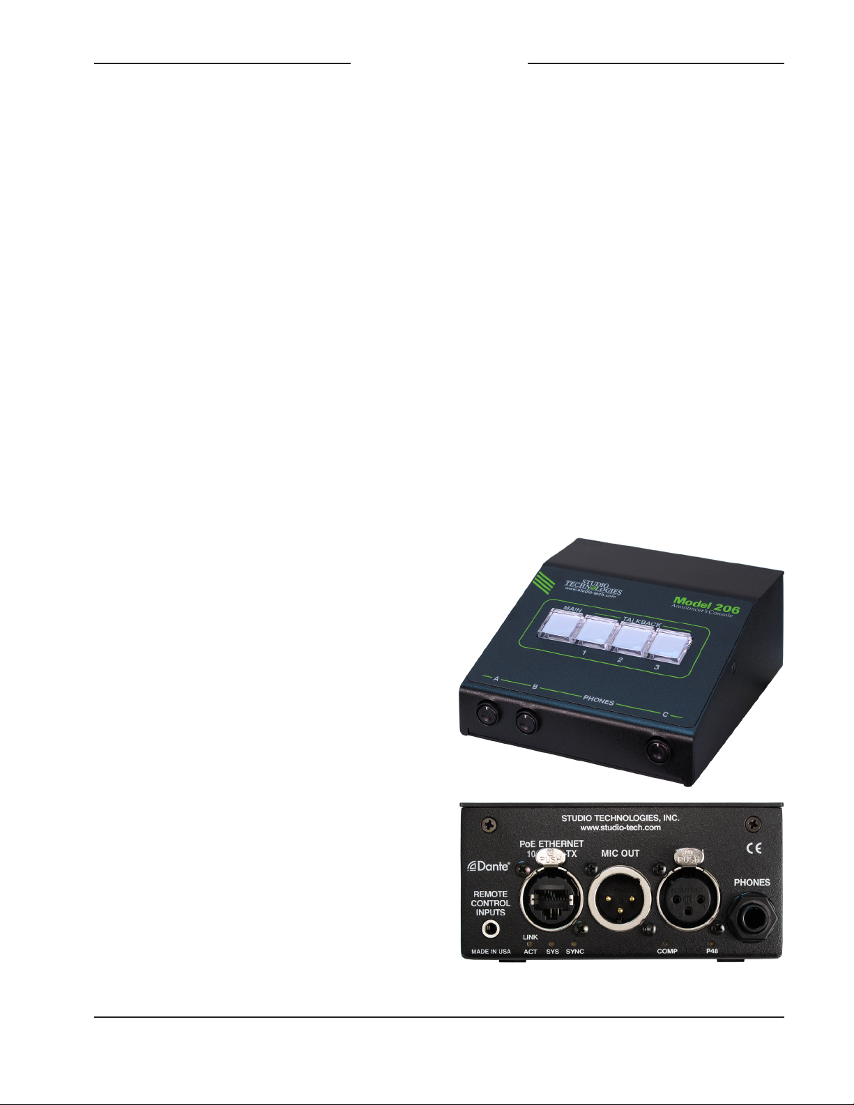
Figure 1. Model 206 Announcer’s Console front
and rear views

Issue 3, August 2020 Model 206 User Guide
Page 6 Studio Technologies, Inc.
MODEL 206
ANNOUNCER’S CONSOLE
be “mix-minus” an integrated sidetone
function can provide the user with a micro-
phone confidence signal. Four Dante audio
output channels, one designated as main
and three named talkback, are routed via
an associated local-area network (LAN) to
inputs on Dante-compatible devices. Four
pushbutton switches, main and three talk-
back, provide the user with direct control
over audio routing. The audio switching is
performed in the digital domain and is virtu-
ally “click-free.”
By providing the main audio signal in two
forms, Dante digital audio and analog
microphone level, the Model 206 makes
integration into a wide range of on-air envi-
ronments easy to accomplish. And with the
three talkback audio channels available as
Dante output channels, routing to inputs on
a variety of devices, such as matrix inter-
com systems, audio consoles, and monitor
loudspeaker systems, is simple and flexible.
Some applications may benefit from not
utilizing the Model 206’s Dante main output
channel. This typically won’t be an issue
of inadequate audio quality but rather a
need to match work-flow requirements. For
example, for lip-sync or transmission pur-
poses it may be optimal to have the on-air
audio transported as an embedded signal
along with the associated camera video. Al-
ternately, all on-air audio sources may need
to connect to inputs on an audio console or
console-related I/O unit. Supporting these
scenarios is not a problem as the Model
206 supplies a microphone output connec-
tion that’s specifically intended for this pur-
pose. Simply connect the unit’s microphone
output connection to the desired analog
input, such as the mic/line input on an ENG-
style camera—that’s it!
The circuitry associated with the Model
206’s analog microphone output is very sim-
ple, essentially a passive path that routes
a signal connected to the microphone input
connector directly to the microphone output
connector. A solid-state circuit, in series
with the mic in-to-mic out path, allows mut-
ing of the signal on the microphone output
connector whenever the Dante main output
channel is muted. Having both the Dante
main output and the microphone outputs
work in tandem can be a valuable resource,
allowing one to serve as the primary on-air
signal source while the other serves as the
backup.
Setup and Operation
Set up, configuration, and operation of the
Model 206 is simple. An etherCON® RJ45
jack is used to interconnect with a standard
twisted-pair Ethernet port associated with
a PoE-enabled network switch. This con-
nection provides both power and bidirec-
tional digital audio. A broadcast headset
or handheld (“stick”) microphone can be
directly connected to the unit’s 3-pin XLR
mic input connector. The input is compatible
with dynamic or condenser microphones.
The integrated P48 phantom power source
provides support for a wide range of con-
denser microphones. A 3-pin XLR micro-
phone output connector provides a “direct
mic out” function for integration with micro-
phone inputs on related devices. Stereo
headphones, the headphone connections
from a stereo or monaural headset, or even
a monaural earpiece can be connected to
the phones output jack.
External switches or contact closures can
be connected to the Model 206’s remote
control inputs to allow activation of the
main and talkback button functions. A low-
voltage/low-current DC output can also

Model 206 User Guide Issue 3, August 2020
Studio Technologies, Inc. Page 7
MODEL 206
ANNOUNCER’S CONSOLE
be implemented providing a Main Out Tally
function. The STcontroller software applica-
tion is used to configure the wide range of
Model 206 operating parameters. This al-
lows the unit’s performance to be optimized
to meet the needs of specific applications.
The user is presented with four pushbutton
switches and three push-in/push-out rotary
level potentiometers This makes it easy to
control the status of the main and talkback
outputs as well as adjusting the signals that
are sent to the headphone channels.
Ethernet Data and PoE
The Model 206 connects to a local area net-
work (LAN) by way of a standard 100 Mb/s
twisted-pair Ethernet interface. The physical
100BASE-TX interconnection is made by
way of a Neutrik® etherCON RJ45 connec-
tor. While compatible with standard RJ45
plugs, etherCON allows a ruggedized and
locking interconnection for harsh or high-
reliability environments.
The Model 206’s operating power is provid-
ed by way of the Ethernet interface using
the 802.3af Power-over-Ethernet (PoE)
standard. This allows fast and efficient inter-
connection with the associated data net-
work. To support PoE power management,
the Model 206’s PoE interface enumerates
(reports) to the power sourcing equipment
(PSE) that it’s a class 2 (low power) device.
If a PoE-enabled Ethernet port can’t be
provided by the associated Ethernet switch
a low-cost PoE midspan power injector can
be utilized.
Dante Audio-over-Ethernet
Audio data is sent to and received from
the Model 206 using the Dante audio-over-
Ethernet media networking technology.
As a Dante-compliant device, the Model
206’s four Dante transmitter (audio output)
channels and four Dante receiver (audio
input) channels can be assigned (routed
or “subscribed”) to other devices using the
Dante Controller software application. The
Dante transmitter and receiver channels
are limited to supporting four Dante flows,
two in each direction. The digital audio’s
bit depth is up to 24 with a sampling rate of
44.1 or 48 kHz. Two bi-color LEDs provide
an indication of the Dante connection sta-
tus. An additional LED displays the status
of the associated Ethernet connection.
The Model 206 is compatible with the
AES67 interoperability standard. In this
mode the four transmitter (output) channels
will function in multicast; unicast is not sup-
ported. In addition, the unit is compatible
with the Dante Domain Manager™ (DDM)
software application.
Audio Quality
The Model 206’s audio performance is
completely “pro.” A low-noise, wide dy-
namic-range microphone preamplifier and
associated voltage-controlled-amplifier
(VCA) dynamics controller (compressor)
ensures that mic input audio quality is
preserved while minimizing the chance of
signal overload. The output of the micro-
phone preamp and compressor is routed
to an analog-to-digital conversion (ADC)
section that supports sampling rates of 44.1
and 48 kHz with a bit depth of up to 24.
The audio signal, now in the digital domain,
routes through a 32-bit microprocessor and
on to the Dante interface section where it is
packetized and prepared for transport over
Ethernet.
Audio input signals arrive via the four Dante
receiver channels and pass into the Model
206’s microprocessor. The supported sam-
pling rates are 44.1 and 48 kHz with a bit
depth of up to 24. Channel routing, head-

Issue 3, August 2020 Model 206 User Guide
Page 8 Studio Technologies, Inc.
MODEL 206
ANNOUNCER’S CONSOLE
phone level control, and sidetone creation
are performed within the digital domain. This
provides flexibility, allows precise control,
and keeps the three level potentiometers
from having to directly handle analog audio
signals. The audio channels destined for the
phones outputs are sent to a high-perfor-
mance digital-to-analog converter and then
on to robust driver circuitry. High signal lev-
els can be provided to a variety of headsets,
headphones, and earpieces.
Configuration Flexibility
The Model 206 can be configured to meet
the needs of specific applications and user
preferences. All configuration choices are
performed using the STcontroller personal
computer software application. There are no
mechanical switch settings or button-press
sequences required to configure how the
unit functions. Selectable parameters include
microphone preamplifier gain, P48 phantom
power on/off, button operation, remote con-
trol inputs (included tally output), headphone
output mode, sidetone operation, and overall
unit operation. The gain of the microphone
preamplifier can be selected from among
four choices. This allows the Model 206 to
match the output sensitivity of a range of
handheld and headset-associated micro-
phones. A low-noise source of P48 phantom
power can be enabled if required to support
condenser (capacitor) microphones.
The main and talkback pushbutton switches
can be individually configured. The main but-
ton can be selected to operate from among
five modes while the talkback buttons can be
selected from among three. These choices
allow the Model 206’s operation to be tai-
lored to meet the specific needs of many ap-
plications. As an example, for on-air sports
applications the main button would typically
be configured to provide a push to mute
(cough) function. The microphone signal
on the Dante main output channel and the
microphone output connector would remain
active unless the talent needs to momen-
tarily disable it. The talkback buttons would
most likely be set to their push to talk modes
as their use would be intermittent.
The Model 206 provides two remote control
inputs. Configuration choices allow these
to be assigned to work in parallel with the
main or talkback pushbutton switches. In
this way, activation of a remote control input
will emulate a user pressing its associated
pushbutton switch. Remote Control Input 1
can also be configured to provide a Main Out
Tally function.
The audio sources and the way in which
they are assigned to the headphone output
channels can be configured from among five
choices. These unique choices allow almost
any required headphone monitoring situa-
tion to be implemented. Whether for use in
on-air sports, an awards show broadcast, or
as a production support tool, the Model 206
should be able to achieve the desired con-
figuration.
Following the mode number is an abbrevi-
ated description of what signal or signals are
assigned to the three potentiometers (pots)
and on to the two headphone output chan-
nels. The potentiometers are labeled A, B,
and C, as can be seen in Figure 1 of this
guide. The format would equate to Mode x
– pot A/pot B/pot C where x equals the mode
number.
• Mode 1 – Ch1L/Ch2R/SidetoneLR:
Provided for broadcast applications where
two monaural channels of talent cueing
audio (“IFB”) need to be independently
sent to the left and right headphone out-
put channels. It would be common for
program audio with director interrupt to

Model 206 User Guide Issue 3, August 2020
Studio Technologies, Inc. Page 9
MODEL 206
ANNOUNCER’S CONSOLE
enter the Model 206 by way of Dante
input (receiver) channel 1 and be sent to
the left headphone output. Program-only
audio, entering the unit by way of Dante
input channel 2, would be sent to the right
headphone output. Pots A and B are used
to adjust the level of those signals. Pot C
is used for the sidetone function where mi-
crophone audio is sent to both the left and
right channels of the headphone output.
• Mode 2 – Ch1LCh2R/BalanceLR/
SidetoneLR: Intended for applications
where a stereo signal enters the Model
206 by way of Dante inputs 1 and 2 and
is routed in stereo to the left and right
channels of the headphone output. In this
mode pot A controls the overall level of
this stereo signal and the pot B controls
its left/right level balance. Pot C is used by
the sidetone function.
• Mode 3 – Ch1LCh2R/Ch3LCh4R/
SidetoneLR: Allows two stereo signals to
be routed as stereo pairs to the two head-
phone output channels. In this mode pot A
adjusts the level of the stereo pair entering
the unit by way of Dante inputs 1 and 2
while pot B adjusts the level of the stereo
pair entering on Dante inputs 3 and 4. Pot
C is used by the sidetone function.
• Mode 4 – Ch1L/Ch2R/Ch3LCh4R:
Allows two monaural input signals to be
independently routed to the left and right
headphone output channels. These audio
signals would enter the Model 206 by way
of Dante input channels 1 and 2. Pots A
and B are used to control the levels of the
signals as they are sent to the left and
right headphone output channels. A stereo
input signal, entering the unit by way of
Dante inputs 3 and 4, are routed to the left
and right headphone outputs. The level of
this stereo pair is controlled by pot C.
• Mode 5 – Ch1LR/Ch2LR/Ch3LCh4R:
Allows two monaural input audio chan-
nels to be sent to both the left and right
headphone output channels. Dante inputs
1 and 2 are used to bring these audio
signals into the Model 206. Pots A and B
are used to control the level of the signals
as they are sent to the headphone output
channels. Pot C is used to control the level
of a stereo input signal as it is routed to
the left and right channels of the head-
phone output. This stereo pair enters the
unit by way of Dante inputs 3 and 4.
The integrated sidetone function can be con-
figured to operate from among four choices.
This allows audio associated with the micro-
phone input and microphone preamplifier to
be returned to the headphone output. This
is important as different applications may
provide a “full mix” or a “mix-minus” talent
cue signal. If a full mix cue signal is provided
then sidetone audio will not be needed and
the function can be disabled. In the case
where a mix-minus signal is present, provid-
ing the user with sidetone at the appropriate
time(s) can be an important means of con-
firming the signal that’s coming from the con-
nected microphone.
The headphone gain range configuration
helps to provide an optimized audio level to
Model 206 users. The appropriate setting will
depend on the specific audio sources pro-
vided to the unit as well as user preference.
Three system modes select the overall way
in which the Model 206 functions. The on-
air mode is optimized for applications where
users will be on-air talent that must maintain
strict separation between on-air and produc-
tion audio channels. Other applications will
benefit from the two available production
modes.

Issue 3, August 2020 Model 206 User Guide
Page 10 Studio Technologies, Inc.
MODEL 206
ANNOUNCER’S CONSOLE
Future Capabilities and
Firmware Updating
The Model 206 was designed so that its
capabilities and performance can be en-
hanced in the future. A USB connector,
located on the unit’s main circuit board
(underneath the unit’s cover), allows the ap-
plication firmware (embedded software) to
be updated using a USB flash drive.
The Model 206 uses the Audinate Ultimo™
integrated circuit to implement the Dante
interface. The firmware in this integrated
circuit can be updated via the Ethernet con-
nection, helping to ensure that its capabili-
ties remain up to date.
Getting Started
What’s Included
Included in the shipping carton are a Model
206 Announcer’s Console and a printed
copy of this guide. As a device that is
Power-over-Ethernet (PoE) powered, no
external power source is provided. In most
applications an Ethernet switch with PoE
capability will be utilized. If that’s not avail-
able a PoE midspan power injector can be
used.
Connections
In this section signal interconnections will
be made using the five connectors located
on the back of the Model 206’s enclosure.
An Ethernet data connection with Power-
over-Ethernet (PoE) capability will be made
using either a standard RJ45 patch cable or
an etherCON protected RJ45 plug. A mi-
crophone will be connected using a cable-
mounted 3-pin male XLR connector. A set
of headphones or an earpiece will be con-
nected by way of a ¼-inch plug. If desired,
the Model 206’s microphone-level output
may be interfaced with other equipment
using a cable terminated with a standard
3-pin female XLR connector. Special ap-
plications may utilize the two remote control
inputs that are accessible using a 3.5 mm
3-conductor jack. Remote Control Input 1
can be configured such that it provides a
tally output.
Ethernet Connection with PoE
A 100BASE-TX Ethernet connection that
supports Power-over-Ethernet (PoE) is
required for Model 206 operation. This one
connection will provide both the Ethernet
data interface and power for the Model
206’s circuitry. A 10BASE-T connection is
not sufficient and a 1000BASE-T (“GigE”)
connection is not supported unless it can
automatically “fall back” to 100BASE-TX op-
eration. The Model 206 supports Ethernet
switch power management, enumerating
itself as a PoE class 2 device.
The Ethernet connection is made by way of
a Neutrik etherCON protected RJ45 con-
nector that is located on the back of the
Model 206’s enclosure. This allows connec-
tion by way of a cable-mounted etherCON
connector or a standard RJ45 plug. The
Model 206’s Ethernet interface supports
auto MDI/MDI-X so that a “cross-over” or
“reversing” cable will never be required.
Ethernet Connection without PoE
As previously discussed in this guide, the
Model 206 was designed such that the
Ethernet connection will provide both data
and Power-over-Ethernet (PoE) power.
There may be situations where the as-
sociated Ethernet switch does not provide
PoE power. In such cases an external PoE
midspan power injector can be used. If the
selected midspan power injector is 802.3af-
compatible it should function correctly.

Model 206 User Guide Issue 3, August 2020
Studio Technologies, Inc. Page 11
MODEL 206
ANNOUNCER’S CONSOLE
Midspan units are available from a variety
of sources, including many online retailers.
Microphone Input
The Model 206 provides a 3-pin female
XLR connector that allows a balanced
dynamic or phantom powered condenser
powered microphone to be connected. The
microphone can be a standalone handheld
(“stick”) type or can be part of a broadcast-
style headset. The Model 206’s microphone
input is directly compatible with balanced
dynamic or P48 phantom powered micro-
phones. A microphone should be connected
such that its associated XLR connector has
pin 1 as common, pin 2 as signal high (+),
and pin 3 as signal low (–). A configura-
tion setting allows the P48 phantom power
source to be enabled or disabled as de-
sired. Details on configuration settings will
be described later in this guide.
While the Model 206 provides an excellent
source of P48 phantom power, it’s possible
that an input on an associated piece of
equipment is already providing microphone
power. This could be connected to the
Model 206 by way of the microphone output
connector. This would not create a problem
since the circuitry that connects audio from
the Model 206’s microphone output con-
nector to the Model 206’s microphone input
connector will pass this microphone power
through without interruption. This situation
could be relevant when the Model 206’s
microphone output connector is interfaced
with the microphone input on a broadcast
camera, audio console, microphone mixer,
or similar equipment. Inputs on these de-
vices would typically offer phantom power
which in some cases may have been
enabled.
Headphone Output
The Model 206 provides a 2-channel
headphone output interfaced by way of a
3-conductor ¼-inch phone jack. Devices
such as stereo headphones or stereo
(“dual-muff”) broadcast-style headsets can
be directly connected using a 3-conductor
¼-inch plug. Following the usual convention
the left channel should be terminated on the
tip lead, the right channel on the ring lead,
and common on the sleeve lead.
It’s also possible to use a monaural (“single-
muff”) headset or broadcast-type single
earbud but in these cases care must be
taken. If a 3-conductor ¼-inch plug is used
by a device it should be wired to the tip and
sleeve leads; the plug’s ring lead should be
left unconnected. But it’s also possible that
the monaural device will be terminated on
a 2-conductor (“tip and sleeve”) plug. When
the plug is inserted into the Model 206’s
headphone jack the Model 206’s right head-
phone output channel will be shorted; the
ring lead will be directly connected to the
sleeve lead. This can lead to stress on the
right channel headphone output circuitry as
well as extra current draw. To prevent this
undesirable condition ensure that no input
audio signal is routed to the right head-
phone output channel. Refer to the Configu-
ration section later in this guide for details
on setting the headphone audio routing to
best accomplish this condition.
Microphone Output
A 3-pin male XLR connector provides a
microphone-level output that’s directly
related to the microphone input. Technically
the output is identical to the signal that’s
connected to the microphone input but with
a solid-state muting circuit in series with
the interconnection. When the Model 206’s
Dante main output channel is active the
Issue 3, August 2020 Model 206 User Guide
Page 12 Studio Technologies, Inc.
MODEL 206
ANNOUNCER’S CONSOLE
microphone signal will also pass through to
the Model 206’s microphone output connec-
tor. Whenever the Dante main output chan-
nel is muted the microphone signal does
not pass through to the microphone output
connector; it is muted in an essentially
click-free manner. Refer to Appendix A for a
block diagram of the microphone input and
microphone output circuitry.
The microphone output can be connected
to balanced (differential) analog micro-
phone-level inputs on a variety of devices.
This includes microphone input connec-
tions on remote I/O interfaces associated
with a networked audio console. An ex-
ample of such an interface would be the
Calrec® Hydra2®. The mic inputs on these
devices typically offer microphone power,
high-quality amplification, and conversion
to the digital domain. The output signals of
the interface’s pre-amp channels are trans-
ported to the main electronics or console
surface using a fiber optic interface. In this
type of application the Model 206’s Dante
main output channel would not be used or
would only be used as a backup path.
No preamplifier or other active circuitry
impacts the path from the Model 206’s
microphone input connector to the Model
206’s microphone output connector. But the
signal does pass through a 200 ohm resis-
tor in each “leg” (pin 2 and pin 3) along with
connecting to a solid-state relay contact.
The result is that the source impedance of
a connected microphone will be 400 ohms
greater when presented to the microphone
output connector. This will slightly raise the
theoretical noise floor of the microphone
signal vis-à-vis a directly connected micro-
phone signal but shouldn’t impact any real-
world applications.
Remote Control Inputs
Provision has been made to allow exter-
nal switches or contact closures to mimic
operation of the main and talkback push-
button switches. The exact functioning of
the two remote control inputs is determined
by configuration settings, details of which
are discussed later in this guide. A 3.5 mm
3-conductor jack is located on the Model
206’s back panel and provides access to
the two remote control inputs. The input
circuitry is “active low,” with 3.4 k ohm resis-
tors connected to +3.3 volts DC to act as
input “pull ups.” (In addition, a combination
of resistors and capacitors provide ESD
protection, minimizing the chance of dam-
age due to static discharge or other extra-
neous signals.) A current flow of less than
one milliampere is required for a remote
control input to be recognized as active.
Remote Control Input 1 can also be config-
ured to provide a Main Tally Output func-
tion. This will provide a 3.3 volts DC, 23
milliampere maximum output whenever the
main output function is active. The tally out-
put can directly drive an LED or be utilized
by the input on another piece of equipment.
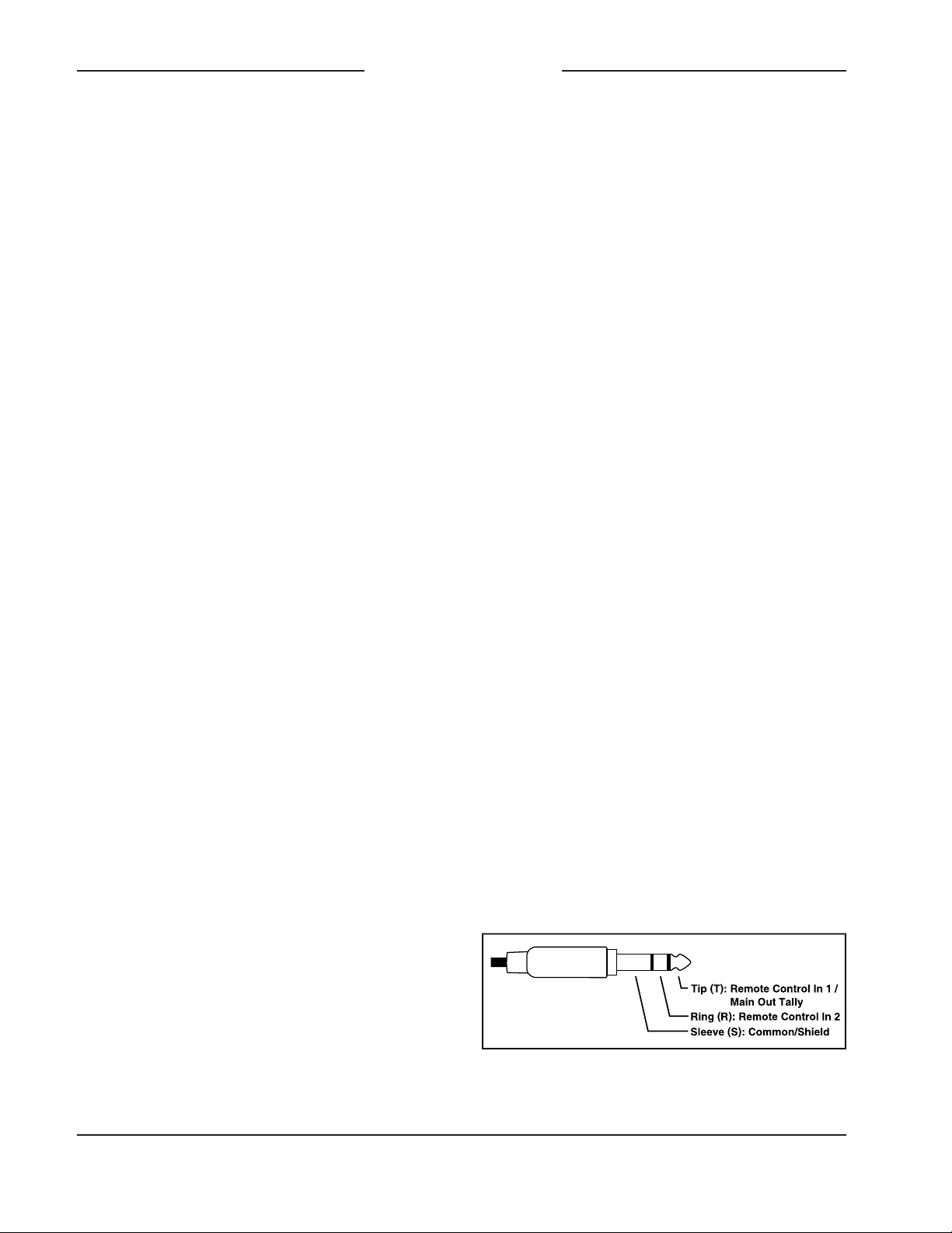
Prepare the interconnecting cable and as-
sociated 3.5 mm 3-conductor plug to reflect
that the tip lead is used by Remote Control
Input 1, the ring lead by Remote Control
Input 2, and the sleeve lead is the connec-
tion to common. Refer to Figure 2 for con-
nection details.
Figure 2. 3.5 mm 3-conductor (TRS) remote
control in pinout diagram

Model 206 User Guide Issue 3, August 2020
Studio Technologies, Inc. Page 13
MODEL 206
ANNOUNCER’S CONSOLE
Dante Configuration
For audio to pass to and from the Model
206 requires that several Dante-related
parameters be configured. These configu-
ration settings will be stored in non-volatile
memory within the Model 206’s circuitry.
Configuration will typically be done with the
Dante Controller software application which
is available for download free of charge at
www.audinate.com. Versions of Dante Con-
troller are available to support Windows and
OS X® operating systems. The Model 206
uses the Ultimo 4-input/4-output integrated
circuit to implement the Dante functionality.
The Model 206 can also be configured to
meet the requirements of the AES67 stan-
dard. This requires a setting to be enabled
within the Device Info section of the Dante
Controller application.
The four Dante transmitter (Tx) channels
associated with the Model 206’s Dante
interface must be assigned to the desired
receiver channels on associated equipment.
This achieves routing the Model 206’s four
output audio channels to the device (or
devices) that will be “listening” to them.
Within Dante Controller a “subscription” is
the term used for routing a transmitter flow
(a group of output channels) to a receiver
flow (a group of input channels). The num-
ber of transmitter flows associated with an
Ultimo integrated circuit is limited to two.
These can either be unicast, multicast, or a
combination of the two. If the Model 206’s
four transmitter channels need to be routed
to more than two flows it’s possible that an
intermediary device with enhanced flow
capability, such as the Studio Technologies’
Model 5422 Dante Intercom Audio Engine,
can be used to “repeat” the signals.
The desired audio sources need to be
routed to the receiver (Rx) channels as-
sociated with the Model 206’s Dante audio
inputs. The unit provides four audio input
channels. The number utilized will depend
on the specific application. Following the
unit’s headphone source and routing con-
figuration selection these audio signals will
be sent to the Model 206’s 2-channel head-
phone output.
The Model 206 supports audio sample rates
of 44.1 and 48 kHz with no pull-up/pull-down
values available. In most cases it’s antici-
pated that the default rate of 48 KHz will be
appropriate. While technically the Model 206
can serve as a clock master for a Dante net-
work (as can all Dante-enabled devices) in
virtually all cases the unit will be configured
to receive “sync” from another device.
The Model 206 has a default Dante device
name of ST-M206 along with a unique
suffix. The suffix identifies the specific Model
206 that is being configured. The suffix’s
actual alpha and/or numeric characters re-
late to the MAC address of the unit’s Ultimo
integrated circuit. The four Dante transmit-
ter (Tx) audio output channels have default
names of Main, Talkback 1, Talkback 2,
and Talkback 3. The four Dante receiver
(Rx) audio input channels have default
names of Headphone Ch1, Headphone
Ch2, Headphone Ch3, and Headphone
Ch4. Using Dante Controller the default
device name and channel names can be
revised as appropriate for the specific
application.
Model 206 Configuration
The STcontroller software application is used
to configure the way in which the Model 206
functions. No DIP switch settings or other
local actions are used to configure the unit.
This makes it imperative that STcontroller be
available for convenient use in a personal
computer that’s connected to the related
LAN.

Issue 3, August 2020 Model 206 User Guide
Page 14 Studio Technologies, Inc.
MODEL 206
ANNOUNCER’S CONSOLE
The configurable functions include:
• P48 phantom power on/off status
• Microphone input gain
• Headphone audio sources and routing
• Headphone gain range and minimum
level
• Sidetone
• Main and talkback button operating
modes
• System operating mode
• Remote control inputs
• Button backlight intensity
Changes made using STcontroller will be
immediately reflected in the unit’s operation;
no Model 206 “reboot” is required. Each
time a change is made the main and talk-
back buttons on the front panel will momen-
tarily flash orange in a distinctive pattern to
indicate that a command from STcontroller
has been received.
Installing STcontroller
STcontroller is available free of charge
on the Studio Technologies’ website (www.
studio-tech.com/stcontroller). STcontroller
versions 2.04.00 and later will fully sup-
port the Model 206. If required, download
and install STcontroller onto a designated
personal computer. This personal computer
must be on the same local area network
(LAN) and subnet as the Model 206 unit or
units that are to be configured. Immediately
after starting STcontroller the application will
locate the devices that it can control. The
one or more Model 206 units to be config-
ured will appear in the device list. Use the
identify command to allow easy recognition
of a specific Model 206 unit. Double-clicking
on a device name will cause the associated
configuration menu to appear. Review the
current configuration and make any chang-
es that are desired.
P48 Phantom Power
STcontroller allows selection of the on/off
status of the microphone input’s P48 phan-
tom power source. The on/off status is
displayed by way of an LED, red in color,
located on the back panel adjacent to the
microphone input connector. Select the sta-
tus of the P48 source to meet the needs of
the connected microphone. No problem will
occur if an external source of P12 or P48
phantom power is present on the connec-
tion made to the microphone output con-
nector. In this case simply turn off the Model
206’s P48 phantom power source. The
external source of microphone power will
“pass thru” from the microphone output con-
nector to the microphone input connector.
Microphone Input Gain
The gain of the Model 206’s microphone
preamplifier can be selected from among
four choices: 35, 43, 52, and 59 dB. The
compressor active LED, orange in color
and visible on the back of the Model 206’s
enclosure adjacent to the microphone input
connector, can act as a guide when setting
the preamp gain. When a voice signal at a
normal level is present on the microphone
input the compressor active LED should
light intermittently. If, for example, it rarely
lights and the gain is set to 43 dB, it might
be a good idea to change the setting to
52 dB. If the LED is lit fully during normal
talking and the gain is set for 52 or 59 dB,
changing it to one of the lower values might
be warranted. There’s no “hard and fast”
rule about which gain setting is appropriate.
But unless otherwise indicated, 43 dB is
typically a good initial choice.

Model 206 User Guide Issue 3, August 2020
Studio Technologies, Inc. Page 15
MODEL 206
ANNOUNCER’S CONSOLE
Headphone Audio Sources and Routing
STcontroller allows selection from among
five headphone audio source and routing
modes. Each mode is distinct and careful
selection will help optimize the Model 206’s
operation for a range of applications.
Mode 1 – Ch1L/Ch2R/SidetoneLR
Mode 1 is provided for on-air applications
where two independent audio sources
need to be routed separately to the two
headphone output channels. Dante input
(receiver) channel 1 will be routed to the
left headphone output channel and pot A
will adjust its level. Dante input (receiver)
channel 2 will be routed to the right head-
phone output channel and pot B will adjust
its level. Pot C will adjust the level of the
sidetone audio as it is sent to both the left
and right headphone output channels.
Mode 2 – Ch1LCh2R/BalanceLR/
SidetoneLR
Mode 2 is provided for stereo applications
that could include live music events that
are distributed via streaming audio or by
way of an over-the-air broadcast. In these
applications it’s typical to want the user to
have a single potentiometer to simultane-
ously adjust the level of a stereo pair while
a separate potentiometer is used to adjust
the left/right level balance.
When set for Mode 2 Dante input chan-
nel 1 will be routed to the left headphone
output channel and Dante input channel 2
will be routed to the right headphone output
channel. Pot A will adjust the overall level
of both headphone output channels. Pot B
will adjust the level balance between the left
and right output channels. Pot C will adjust
the level of the sidetone audio as it is sent
to both the left and right headphone output
channels.
Mode 3 – Ch1LCh2R/Ch3LCh4R/
SidetoneLR
Mode 3 can be useful in applications where
two stereo signals need to be provided to
the user on the left and right headphone out-
put channels. In this mode Dante input chan-
nels 1 and 2 are routed to the left and right
channels of the headphone output. Pot A ad-
justs the level of this stereo pair. Dante input
channels 3 and 4 are also routed to the left
and right channels of the headphone output.
Pot B adjusts the level of this stereo pair as
it is sent to the headphone output channels.
Pot C will adjust the level of the sidetone
audio as it is sent to both the left and right
headphone output channels.
Mode 4 – Ch1L/Ch2R/Ch3LCh4R
Mode 4 is very similar to mode 1 except
instead of providing sidetone another ste-
reo pair can be routed to the left and right
headphone output channels. Dante input
channel 1 is routed to the left channel of the
headphone output and pot A adjusts its level.
Dante input channel 2 is routed to the right
headphone output channel and pot B adjusts
its level. A stereo pair can enter the Model
206 by way of Dante input channels 3 and 4.
These signals, whose level is adjusted using
pot C, are sent to the left and right channels
of the headphone output.
Mode 5 – Ch1LR/Ch2LR/Ch3LCh4R
Model 5 is a unique variation where two mon-
aural signals can be routed to both the left
and right headphone output channels while
a stereo input source is routed in stereo to
the headphone output channels. Dante input
channel 1 will be routed to both the left and
right channels of the headphone output. Its
level is controlled by pot A. Dante input chan-
nel 2 will also be routed to both the left and
right channels of the headphone output. Its
level will be adjusted using pot B. A stereo

Issue 3, August 2020 Model 206 User Guide
Page 16 Studio Technologies, Inc.
MODEL 206
ANNOUNCER’S CONSOLE
pair can enter the Model 206 by way of
Dante input channels 3 and 4. These sig-
nals will be sent, in stereo, to the left and
right channels of the headphone output.
Their level will be adjusted using pot C.
Headphone Gain Range
The overall level of the headphone output
can be configured as desired for specific
applications. The default setting, low, is de-
signed so that users with typical audio input
sources will be inclined to set the rotary
potentiometers at approximately 50% of
rotation. This would be appropriate for most
applications. The high setting would be ap-
plicable in cases where an extreme head-
phone output level is required or the audio
input sources are providing a level that is
lower than typical. Using the high setting in
the former application is not recommended
as hearing damage could result from expo-
sure to high signal levels.
Headphone Minimum Level
A setting in STcontroller is used to configure
the headphone output’s minimum level. In
the –40 dB setting the minimum headphone
output level is approximately 40 dB below
its maximum; the headphone output chan-
nels will never fully mute. This ensures
that any audio signal present on the uti-
lized Dante input channels will always be
present on the headphone output. In most
on-air broadcast applications this is the ap-
propriate setting, ensuring that a minimum
amount of signal is always present. When
full mute is selected moving a level potenti-
ometer to its fully counterclockwise position
will cause its associated headphone output
channel (or channels) to fully mute. If a
potentiometer is set to serve as a balance
control, moving it to either its fully coun-
terclockwise or fully clockwise position will
cause the associated signal to fully mute.
Selecting the full mute mode may be appro-
priate for applications where minimizing the
chance of audio “leakage” is important. This
could occur when during an event the con-
nected headset or headphones are at times
placed on a desk or tabletop.
Note that the action of pot C when con-
figured to provide the sidetone function
(headphone modes 1, 2 or 3) will never be
impacted by the setting for the headphone
minimum level. Whenever pot C is control-
ling the sidetone level it will always cause
the signal to fully mute when it’s set to fully
counterclockwise.
Sidetone Mode
STcontroller allows the Model 206’s side-
tone function to be configured as desired.
Sidetone is audio from the microphone
input that is sent to the headphone output
channels. This can be important, allowing
the user to “hear” themselves for perfor-
mance confirmation and comfort. Making a
specific selection from among the four avail-
able modes will depend on the needs of the
application. If a “full mix” is being provided
to the Model 206’s Dante inputs then locally
provided sidetone won’t be needed and the
off configuration should be selected. The
user will hear themselves by way of audio
signals being routed to the Dante input
channels. But if “mix-minus” audio is being
supplied to the Model 206 then selecting
a headphone source and routing modes
which enables sidetone (headphone modes
1, 2, or 3) can be an important means of
establishing user confidence. Then the
sidetone mode configuration will establish
exactly when sidetone audio will be sent to
the headphone output channels.

Model 206 User Guide Issue 3, August 2020
Studio Technologies, Inc. Page 17
MODEL 206
ANNOUNCER’S CONSOLE
• Push to Talk: If this mode is selected
the main button function will normally be
inactive and the button’s red LED will be
lit. The audio signal associated with the
microphone input will not be routed to the
Dante main output channel and the mi-
crophone output connector will be muted.
Whenever the main button is pressed
the audio signal will become active on
the Dante output channel and the micro-
phone output connector. In addition, the
button’s green LED will light.
• Latching: If this mode is selected the
main button’s function will alternate
between its active and inactive states
whenever the main button is pressed.
Upon power up the function will be in its
inactive state and the red LED associated
with the button will be lit.
• Push to Talk/Tap to Latch: This mode is
a combination of the Push to Talk and
Latching modes. It’s similar to the way
talk pushbutton switches function on
user stations associated with broadcast
or production intercom systems. If the
main button is pressed and held the main
button’s function will be active. It will stay
active until the main button is released.
If the main button is momentarily “tapped”
the main button’s status will change,
either from inactive-to-active or from ac-
tive-to-inactive. Upon Model 206 power
up the main button will be in its inactive
state and its red LED will be lit.
• Push to Mute/Tap to Latch: This mode is
a combination of the Push to Mute and
Latching modes. Whenever the main
button is momentarily “tapped” the main
button’s status will change, either from
active-to-inactive or inactive-to-active.
When the main button function is active
its green LED will be lit. The audio signal
Four sidetone modes are available:
• Off: In this mode the sidetone function
is not active.
• Main Button: In this mode the sidetone
function will be active whenever the audio
signal associated with the microphone
input is present on the Dante main output
channel and the microphone output
connector.
• Talkback Buttons: In this mode the side-
tone function will be active whenever one
or more of the talkback functions are ac-
tive and the audio signal is present on the
talkback 1, talkback 2, and/or talkback 3
Dante output channels.
• Main and Talkback Buttons: In this mode
the sidetone function will be active when-
ever the audio signal associated with the
mic input is present on the Dante main
output channel and the microphone out-
put connector. The sidetone function will
also be active whenever one or more of
the talkback functions are active.
Button Operation – Main
STcontroller allows the configuration of the
main button to be selected. There are five
mode choices available:
• Push to Mute: If this mode is selected
the main button function will normally be
active and its green LED lit. The audio
signal associated with the microphone in-
put will be routed to both the Dante main
output channel and the microphone out-
put connector. Whenever the main button
is pressed the audio signal will mute on
both the Dante main output channel and
the microphone output connector; the but-
ton’s LED will change from green to red.

Issue 3, August 2020 Model 206 User Guide
Page 18 Studio Technologies, Inc.
MODEL 206
ANNOUNCER’S CONSOLE
the status of the function will change,
either from inactive-to-active or from ac-
tive-to-inactive. Upon Model 206 power up
the talkback buttons will be in their inactive
state and their LEDs will not be lit.
System Operating Mode
The system mode configures the overall
manner in which the Model 206 operates.
Specifically, it determines how the Dante
main output channel and the microphone
output connector operate vis-à-vis the talk-
back functions. The system mode can also
impact one facet of the headphone output’s
function. There are three system modes
available. Understanding how each specifi-
cally impacts Model 206 operation will help
to ensure that the desired operation is ob-
tained and that maximum usability will occur.
On-Air
When selected to the on-air mode, audio
on the Dante main output channel and the
microphone output connector will always
mute whenever the talkback 1, talkback 2,
or talkback 3 functions are active. The on-air
mode should be selected for all on-air broad-
cast applications when it’s imperative that
the “on-air” audio signal be muted whenever
on-air talent uses a talkback function to com-
municate with production personnel.
Production
When the system mode is set for production,
the audio signals on the Dante main output
channel and microphone output connector
are never muted in response to talkback
function activity. The mic off/off function
operates independently of the talkback
functions. This mode allows the Dante main
output channel to be used, for example, as
an additional talkback output. In this way,
the Dante main output channel and the three
talkback output channels can be used sepa-
rately and not impact each other. This also
associated with the microphone input will
be routed to both the Dante main out-
put channel and the microphone output
connector. Whenever the main button is
pressed and held the audio signal will
mute on both the Dante main output
channel and the microphone output con-
nector and the button’s LED will change
from green to red. It will stay in this con-
dition until the main button is released.
Upon Model 206 power up the main but-
ton will be in its inactive state and its red
LED will be lit.
Button Operation – Talkback
The manner in which the three talkback but-
tons function can be configured. One set-
ting applies to both talkback buttons. There
are three mode choices available:
• Push to Talk: If this mode is selected the
talkback functions will normally be inac-
tive and the LED associated with each
button will not be lit. Whenever a talkback
button is pressed its associated talkback
function will become active and its green
LED will light.
• Latching: If this mode is selected the
talkback functions will alternate between
their active and inactive states whenever
a talkback button is pressed. Upon power
up the talkback functions will be in their
inactive state and their button LEDs will
not be lit.
• Push to Talk/Tap to Latch: This mode is
a combination of the Push to Talk and
Latching modes. It’s similar to the way
talk pushbutton switches function on user
stations associated with broadcast or pro-
duction intercom systems. If a talkback
button is pressed and held its talkback
function will be active. It will stay active
until the talkback button is released. If a
talkback button is momentarily “tapped”

Model 206 User Guide Issue 3, August 2020
Studio Technologies, Inc. Page 19
MODEL 206
ANNOUNCER’S CONSOLE
needs of an application, specifically being
configured to perform optimally vis-à-vis the
amount of ambient light present in the Model
206’s location. The choices are low and high.
Operation
At this point all connections and configura-
tion steps should have been completed and
everything should be ready for Model 206
operation to commence. An Ethernet connec-
tion with Power-over-Ethernet (PoE) capa-
bility should have been made. Alternately, a
midspan power injector, in “series” with the
Ethernet connection, should have been put
into place. A microphone and headphones or
earbud should have been connected. Alter-
nately, a broadcast-style headset may have
been connected. If desired, a connection to
the microphone output should have been
made. Some applications may utilize either
or both of the remote control inputs. Remote
Control Input 1 can provide a low-voltage
DC tally output that is active whenever the
main output function is active. It may be used
to light a status LED or trigger the input on
another piece of equipment.
The Model 206 should have been placed
in the desired physical location. Using the
Studio Technologies’ STcontroller software
application the unit’s configuration should
have been selected to meet the needs of the
specific application. The Model 206’s Dante
configuration settings should have been
selected using the Dante Controller software
application. In this way, the unit’s four Dante
audio output channels (Dante transmitter
channels) and four Dante audio input chan-
nels (Dante receiver channels) should have
been routed, by way of Dante “subscriptions,”
to the receiver and transmitter channels on
associated Dante-enabled equipment.
allows both the main and talkback push-
buttons to be used simultaneously. When
selected for the correct application, the pro-
duction mode can prove to be very useful.
But it’s not appropriate for on-air use!
Production with Dim
This mode is identical to the production
mode with the exception that the headphone
output reduces in level (“dims”) whenever
the main, talkback 1, talkback 2, or talkback
3 functions are active. This mode was spe-
cifically provided to minimize the chance that
acoustical feedback will occur in applica-
tions where the headphone output is con-
nected to the inputs on amplified speakers
(or inputs on an amplifier associated with
loudspeakers). In this mode the level of the
headphone output channels is reduced by
18 dB whenever a main or talkback function
is active. This mode is not appropriate when
headphones are going to be connected to
the Model 206!
Remote Control Inputs
There are two remote control inputs which
can be individually configured. Remote Con-
trol Input 1 can be configured to be disabled
(off), to mimic the action of either the main or
talkback pushbutton switches, or to provide
a main output tally function. Remote Control
Input 2 can be configured to be disabled
(off), or mimic the action of either the main or
talkback pushbutton switches.
Button Backlight Intensity
The caps (top surfaces) of the four push-
button switches are able to be lit using in-
ternal LEDs, one red and one green. When
they light and with what color depends on
the configuration of the Model 206 and the
current operating condition. The intensity
of these LEDs can be adjusted to meet the

Issue 3, August 2020 Model 206 User Guide
Page 20 Studio Technologies, Inc.
MODEL 206
ANNOUNCER’S CONSOLE
seconds the LED identification pattern will
cease and normal Model 206 button
LED and Dante status LED operation will
resume.
Ethernet and Dante Status
LEDs
Three status LEDs are located below the
etherCON RJ45 connector on the Model
206’s back panel. The LINK ACT LED will
light green whenever an active connection
to a 100 Mb/s Ethernet network has been
established. It will then flash in response to
all Ethernet data packet activity. The SYS
and SYNC LEDs display the operating sta-
tus of the Dante interface and its associated
network activity. The SYS LED will light
red upon Model 206 power up to indicate
that the Dante interface is not ready. After
a short interval it will light green to indicate
that it is ready to pass data with another
Dante device. The SYNC LED will light red
when the Model 206 is not synchronized
with a Dante network. It will light solid green
when the Model 206 is synchronized with a
Dante network and an external clock source
(timing reference) is being received. It will
slowly flash green when this specific Model
206 is part of a Dante network and is serv-
ing as the clock master. It’s possible that
up to 30 seconds may be required for the
SYNC LED to reach its final state.
P48 Status LED
An LED indicator is located on the back
panel adjacent to the microphone input
connector. It is labeled P48 and will light red
whenever the P48 phantom power source
is active and providing power to the micro-
phone input.
Initial Operation
The Model 206 will start to function as soon
as a Power-over-Ethernet (PoE) power
source is connected. However, it may take
20 to 30 seconds for full operation to com-
mence. Upon initial power up the three
status LEDs, located on the back panel
below the RJ45 jack, will begin to light as
network and Dante connections are estab-
lished. The COMP LED, adjacent to the
microphone input connector, may or may
not flash momentarily. The P48 LED, also
located adjacent to the microphone input
connector, will flash once to indicate that
it is functioning. The red and green LEDs
within the main and talkback pushbutton
switches will light in a short test sequence
to indicate that the application firmware
(embedded software) has started. Once
that sequence has completed and the
Dante connection has been established full
operation will begin. The various LEDs will
then become operational, displaying the
status of their designated functions.
How to Identify a Specific
Model 206
Functions within the Dante Controller and
STcontroller software applications allow
a specific Model 206 unit to be identified.
Each application provides an “eyeball” icon
that when clicked will activate the identify
function. When identify is selected it will
send a command to a specific Model 206
unit. On that unit the LEDs associated with
the main and talkback pushbutton switches
will “flash” orange approximately eight
times (the actual on/off status of the buttons
will not change). In addition, the SYS and
SYNC status LEDs, located directly below
the etherCON RJ45 connector on the back
panel, will slowly flash green. After a few
Other manuals for 206
2
This manual suits for next models
1
Table of contents
Other Studio Technologies Dj Equipment manuals


