STYLE P 50 User manual
FBT ELETTRONICAS.p.A. - Via Paolo Soprani 1 - Zona Ind.le Squartabue - 62019 RECANATI (MC) - ITALY
ALL PURPOSE SPEAKER SYSTEM
ISTRUZIONI D’USO
INSTRUCTIONS FOR USE
UK
A 50 / A 40T
S 50 / S 40T
P 50 / P 40T

La nuova gamma di diffusori acustici STYLE uniscono
l’ottima qualità della riproduzione acustica ad un design
innovativo, da cui scaturisce un concetto nuovo,
un’estetica accattivante, in grado di soddisfare svariate
esigenze dal punto di vista architettonico. Il diffusore
acustico non dovrà più essere un elemento da
nascondere rischiando di compromettere la qualità del
suono, bensì diventa un elemento integrato
nell'ambiente, dove il risultato è l'unione tra forma e
funzione, tra scomparsa totale ed acustica. Seguendo
la natura stessa, dove il suono si espande in tutte le
direzioni, è stato sviluppato così un altoparlante che
riesce a riprodurre una sensazione sonora naturale.
Mentre in natura il suono si espande a 360°, i diffusori
convenzionali propagano il suono in forma conica e
quindi con un angolo ristretto. Grazie alla forma conica
della membrana, i diffusori acustici STYLE ottengono
una diffusione a 360° fino alle frequenze più alte. La
diffusione si realizza in tutte le direzioni con grande
precisione e naturalezza anche a volumi acustici molto
elevati. La nuova tecnologia fa dimenticare la diffusione
sonora geometrica alla quale si è abituati, offrendo la
possibilità di abbracciare in ogni ambiente un effetto
sonoro olografico e tridimensionale. Grazie al materiale
con cui sono realizzati e grazie all'altoparlante in
alluminio possono essere installati all'aperto,
resistendo alla varie condizioni atmosferiche.
La serie STYLE comprende:
STYLE A50: a plafoniera, impedenza 16 Ohm,
potenza nominale 50W RMS, potenza musicale 90W.
STYLE A40T: con trasformatore di linea
STYLE P50: a sospensione, impedenza 16 Ohm,
potenza nominale 50W RMS, potenza musicale 90W.
STYLE P40T: con trasformatore di linea
STYLE S50: a parete, impedenza 16 Ohm, potenza
nominale 50W RMS, potenza musicale 90W.
STYLE S40T: con trasformatore di linea
The new range of STYLE sound speakers combines
high quality sound play with innovative design, creating
a new concept and a catching look that are able to
satisfy several architectural needs. The sound speaker
shall no more be hidden, with the risk of affecting the
sound quality. Instead, it will be integrated in the
environment, combining form and function, acoustics
and integration in the environment. The nature itself has
inspired this loudspeaker; in the nature the sound
spreads to all directions, and, hence, we have
developed a speaker that could reproduce a natural
sound feeling. The sound diffusion in the nature is 360°,
whereas in standard speakers its propagation is conic-
shaped and, hence, has a narrow angle. Thanks to the
conic-shape of the diaphragm, STYLE sound speakers
provide a 360° sound diffusion, reaching even the
highest frequencies. The sound diffusion spreads to all
directions, keeping the sound natural and accurate
even when the volume is very high. Thanks to this new
technology you will immediately forget the geometric
diffusion you are used to and you will be able to recreate
a holographic and three-dimensional sound effect in
any environment. Moreover, thanks to the material,
STYLE speakers are made of and to the aluminium
loudspeaker, they are suitable for outdoor mounting
and resist to various weather conditions.
The STYLE series includes:
STYLE A50: ceiling speakers, impedance 16 Ohms,
rated power 50W RMS, musical power 90W.
STYLE A40T: with line transformer
STYLE P50: suspended speakers, impedance 16
Ohms, rated power 50W RMS, musical power 90W.
STYLE P40T: with line transformer
STYLE S50: wall speakers, impedance 16 Ohms,
rated power 50W RMS, musical power 90W.
STYLE S40T: with line transformer
PRESENTAZIONE
LINEE DI ALIMENTAZIONE DEGLI ALTOPARLANTI
SISTEMI A DIFFUSORI DISTRIBUITI
COLLEGAMENTO CON GLI AMPLIFICATORI
STYLE A50 / A40T
STYLE P50 / P40T
STYLE S50 / S40T
SPECIFICHE TECNICHE
INFORMAZIONI GENERALI SUI METODI DI INSTALLAZIONE
1
2
3
4
5
6
7
8
9-10
INTRODUCTION
SPEAKER LINES POWER SUPPLY
DISTRIBUITED SPEAKER SYSTEMS
CONNECTION TO THE AMPLIFIERS
STYLE A50 / A40T
STYLE P50 / P40T
STYLE S50 / S40T
TECHNICAL SPECIFICATIONS
GENERAL INFORMATION ON THE VARIOUS METHODS OF
INSTALLATION
1
2
3
4
5
6
7
8
9-10
1

Le linee di alimentazione degli altoparlanti debbono
essere realizzati con cavi inguainati.
Per evitare rischi di scossa elettrica non toccare i fili
scoperti collegati ai morsetti dell'amplificatore quando
questo è in funzione.
L'amplificatore deve essere alimentato dalla tensione di
rete solo dopo aver terminato tutti i collegamenti.
LINEE A BASSA IMPEDENZA
L'impedenza equivalente degli altoparlanti connessi
deve essere uguale o superiore a quella indicata sui
morsetti di uscita dell'amplificatore.
LINEE A TENSIONE COSTANTE
Ogni altoparlante deve essere provvisto di
trasformatore di linea con una tensione di ingresso
uguale a quella di linea.
La somma delle potenze degli altoparlanti non deve
eccedere la potenza di uscita dell'amplificatore.
To connect loudspeakers use boot's cables exclusively.
To avoid the risk of electrical shock never touch the bare
conductors leading to the output terminals of the
amplifier when it is in operation.
The unit must only be supplied from the mains after all
connections have been completed.
LOW IMPEDANCE LINES
The total impedance of the speakers connected must
correspond to that selected on the amplifier's output
terminals.
CONSTANT VOLTAGE LINES
Each speaker must be equipped with a line transformer
with an input voltage equal to that of the line.
The sum of the power capacities of the speakers must
not exceed the output power capacity of the amplifier.
Speakers with series connection
Impedance of series speakers
Speakers with parallel connection
Impedance of parallel speakers
2

SISTEMI A DIFFUSORI DISTRIBUITI
I sistemi a diffusori distribuiti per paging e musica sono
molto comuni in realtà come alberghi, ristoranti, uffici,
scuole, ecc. In questi sistemi svariati diffusori sono
delocalizzati su tutta l'area.
Tale sistema multispeaker consiste in un amplificatore o
canale di amplificazione che pilota uno o più speaker
dotati di trasformatore.
I trasformatori riducono la tensione di linea ad un livello
più basso, tale da pilotare i diffusori, e sono collegati a
cavallo della coppia di conduttori.
La combinazione del trasformatore e dello speaker in
linea presenta una impedenza molto più alta verso
l'amplificatore, rispetto al caso di diffusore singolo, cosa
che rende possibile aggiungere molti più speakers su
una singola linea di segnale in potenza.
DISTRIBUITED SPEAKER SYSTEMS
The distribuited speaker systems for music and paging
are often used in hotels, restaurants, offices, schools,
etc. In these systems several speakers are located all
over the area.
These multispeaker systems include one amplifier or
one amplification channel that drives one or more
speakers equipped with transformers.
The transformers reduce the line voltage to a lower
level, so to drive speakers, and are connected between
the conductor pair.
Compared to a single speaker, the combination of a
transformer and a speaker on the line has a much
higher impedance toward the amplifier, and this makes
it possible to add several speakers to a single power
signal line.
AMPLIFICATORE / POWER AMPLIFIER
100V
100V
Table of in parallel impedances
Standard distributed speaker system
3

CONSIGLI SUL CABLAGGIO DEGLI INGRESSI
- Per tutti i collegamenti di ingresso utilizzare solo cavi
schermati.
- Evitare, se possibile, l'impiego di linee sbilanciate negli
apparati professionali; se non si ha altra scelta,
mantenere i cavi quanto più corti possibile.
- Per minimizzare i rumori di tipo "hum" evitare di
stendere cavi d'ingresso a basso livello
estremamente lunghi, cavi di uscita ad alto livello e
cavi di alimentazione AC nella stessa canalina.
CONSIGLI SUL CABLAGGIO DELLE USCITE
- A prevenzione di eventuali cortocircuiti, coprire o
isolare le terminazioni libere dei cavi o dei connettori.
- N o n u t i l i z z a r e c o n n e t t o r i c h e p o s s a n o
accidentalmente legare insieme i diversi conduttori
quando si effettuano o si rompono le connessioni.
- Non utilizzare mai connettori che possano essere
inseriti in prese di corrente AC; l'inserimento
accidentale di alimentazione AC può essere una
esperienza deleteria per tutto l'impianto.
RECOMMENDATIONS ON INPUT WIRING
- Please only use shielded cables for all input
connections.
- If possible avoid using unbalanced lines for
professional equipments; if there is no other option
use the shortest cables possible.
- To reduce noise, e.g. hum, as much as possible, avoid
laying excessively long low level input cables, as well
as high level output cables and AC power supply
cables in the same wireway.
RECOMMENDATIONS ON OUTPUT WIRING
- In order to prevent short-circuits, please cover or
isolate free cable ends or connector ends.
- Do not use connectors that could accidentally link
several conductors together when making or breaking
connections.
- Never use connectors that can be connected to AC
outlets; accidentally connecting AC power can
damage the whole equipment.
COLLEGAMENTO CON GLI AMPLIFICATORI CONNECTION TO THE AMPLIFIERS
4

A 50 / A 40T
STYLE A50 è stato sviluppato in modo mirato come
altoparlante da incasso a soffitto per requisiti
architettonici di alto livello. Grazie alla geometria conica
della membrana si raggiunge una dispersione fino a
180° anche alle frequenze più alte. La diffusione
orizzontale del suono è a 360°. Irresistibile è
l'eccellente qualità di riproduzione e la fedeltà del
suono, sia nella resa del parlato che nella riproduzione
di registrazioni stereo di alta qualità. Grazie a questa
diffusione del suono ad angolo molto ampio e
all'efficienza acustica straordinaria, STYLE A50 è un
eccellente sistema audio a tutte le frequenze per
musica di sottofondo in ambienti privati, diffusione in
sale, ambienti pubblici, boutique, negozi, gallerie,
musei, ecc., nonché per impieghi con altissimi requisiti
de l pa r l at o , co m e sa l e pe r con f ere n ze,
videoconferenze, applicazioni surround e simili.
STYLE A50 has been specifically developed as an
embedded ceiling mounting loudspeaker for
sophisticated architectural requirements. The conical
geometry of the membrane provides a dispersion of up
to 180° even at the highest frequencies. The
loudspeakers give a 360° horizontal diffusion of the
sound. The excellent quality reproduction and sound
fidelity is irresistible, both in the rendering of spoken
words and in the reproduction of high quality stereo
recordings. Thanks to this very wide angle sound
diffusion and extraordinary sound efficiency, STYLE
A50 is an excellent audio system at all frequencies for
background music in private areas, diffusion in halls,
pubblic areas, boutiques, shops, galleries, museums,
etc., as well as for uses requiring an excellent
understanding of the spoken word, such as conference
halls, videoconferences, surround sound and similar
applications.
130 mm / 5,11 inch
180 mm / 7,08 inch
Il dispositivo di montaggio è concepito per rivestimenti a
soffitto con uno spessore massimo di 35mm. STYLE
A50 viene fissato al bordo superiore del controsoffitto
con tre staffe a graffetta; per il montaggio è necessario
un foro di 130mm; la profondità di incasso dal bordo
inferiore del soffitto misura 65mm (100mm per il
modello A40T). Cavi per altoparlanti con un diametro di
almeno 1,5mmq. collegano l'unità di amplificazione
centrale alle posizioni previste. Per garantire una
qualità massima del suono, si consiglia di cablare gli
altoparlanti secondo la loro posizione (canale
sinistro.....sinistra, ecc ). Se si usano più sistemi per una
acustica stereo nell'ambiente, i canali devono essere
disposti in modo alternato o diagonalmente, per offrire
all'ascoltatore una impressione uditiva stereoacustica.
MONTAGGIO FINALE:
Durante l'installazione dell'altoparlante il sistema viene
centrato automaticamente grazie a tre tasselli.
L'altoparlante viene collegato all'impianto tramite
attacchi a pinza (rispettare i poli: + = rosso, - = nero) e
adattato al foro nel soffitto. Le tre viti torx sul lato
anteriore dell'altoparlante fissano le graffette e
ancorano il sistema saldamente al soffitto. Se si usa un
avvitatore elettrico si consiglia di procedere lentamente
e con cautela onde evitare danni alle graffette di
fissaggio. Prima di serrare le viti effettuare un mezzo
giro in senso antiorario, per garantire un inserimento
ottimale nella filettatura. Se si desidera, le teste delle viti
possono essere coperte con dei tappi facilmente
applicabili a pressione.
The mounting device has been designed for ceiling
coverings with a maximum thickness of 35mm. STYLE
A50 is fixed to the upper edge of the false ceiling using
three pole clips. Mounting requires a hole of 130mm;
the embedding depth from the lower edge of the ceiling
measures 65mm (100mm for model A40T). Cables for
loudspeakers with a diameter of at least 1,5mmq
connect the central amplification unit to the intended
positions. To guarantee maximum sound quality, the
loudspeakers should be cabled according to their
position (left channel.....left, etc.). If more than one
system is used for stereo sound, the channels must be
arranged alternately or diagonally to provide the listener
with a stereo-acoustic sound.
FINAL MOUNTING:
During installation of loudspeaker, the system is
automatically centred by way of three pins. The
loudspeaker is connected to the system using alligator
clips (always connect to the correct poles: + = red, - =
black) and fitted to the hole in the ceiling. The three torx
screws on the front of the loudspeaker fix the clips in
place and anchor the system firmly to the ceiling. If an
electrical screwdriver is used, proceed slowly and
cautiously to prevent any damage to the fixing clips.
Before tightening the screws, give them a half-turn anti-
clockwise to ensure optimal insertion in the threading. If
so wished, the screw heads can be covered with easily
applied press-on caps.
5

P 50 / P 40T
STYLE P50 è la risposta a requisiti di progetto in cui i
soffitti chiusi non permettono l'uso di altoparlanti da
incasso. Il suo design atipico colpisce grazie alla
stravaganza individuale e alle linee essenziali. Dal
punto di vista del suono, STYLE P50 è tuttavia un lupo
travestito da agnellino; infatti grazie alla geometria
conica della mambrana raggiunge una dispersione a
360° anche alle frequenze più alte. Irresistibile è la sua
eccellente qualità di riproduzione e la fedeltà del suono,
sia nella resa del parlato che nella riproduzione di
registrazioni stereo di alta qualità. Grazie a questa
diffusione del suono ad angolo molto ampio e
all'efficienza acustica straordinaria, STYLE P50 è un
eccellente sistema audio a tutte le frequenze, per
musica di sottofondo in ambienti piccoli, diffusione in
sale, ambienti pubblici, boutique, negozi, passaggi,
gallerie, musei, ecc.
STYLE P50 is an ideal solution for projects where the
closed ceilings do not permit the use of embedded
ceiling mounted loudspeakers. Its atypical design is
striking thanks to its individual extravagance and clean
lines. In terms of its sound, STYLE P50 is a wolf
disguised as a lamb. The conical geometry of the
membrane provides a dispersion of up to 360° even at
the highest frequencies. The excellent quality of
reproduction and sound fidelity is irresistible, both in the
rendering of spoken words and in the reproduction of
high quality stereo recordings. Thanks to this very wide
angle diffusion of the sound and its extraordinary sound
efficiency, STYLE P50 is an excellent audio system at
all frequencies for background music in small areas,
diffusion in halls, public areas, boutiques, shops,
passageways, galleries, museums, etc.
125mm / 4,92 inch
70 mm
2,75 inch
134 mm / 5,27 inch
60 mm
2,36 inch
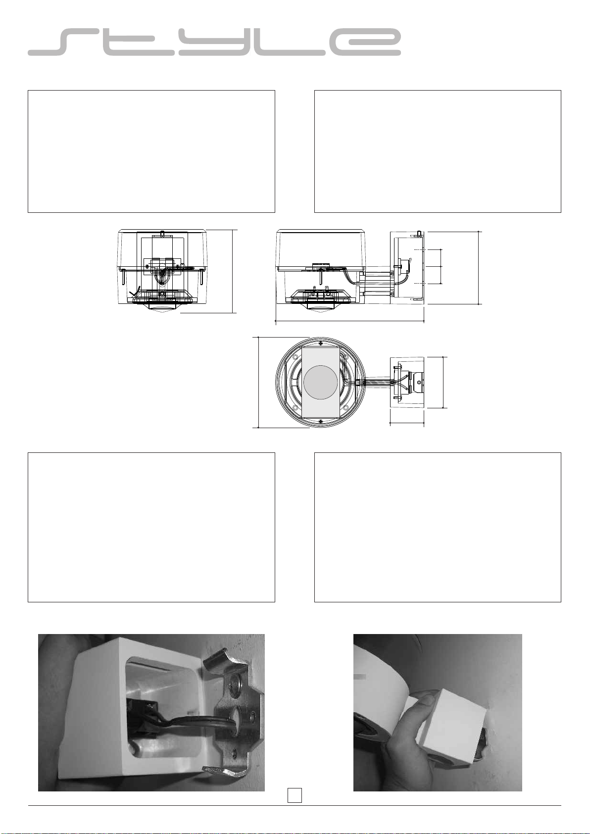
MONTAGGIO FINALE:
L'installazione della STYLE P50 viene effettuata in
modo semplice e completo grazie agli accessori
presenti. Il foro per il fissaggio dell'altoparlante deve
essere effettuato direttamente vicino all'uscita del cavo,
per far si che, una volta montata, la copertura del
sistema nasconda tutti gli elementi di installazione.
FINAL MOUNTING:
The installation of STYLE P50 can be carried out in a
simple and complete manner thanks to the accessories
supplied. The hole for fixing the loudspeaker must be
made near the cable exit point to ensure the system
cover conceals all installation elements once mounted.
6
S 50 / S 40T
STYLE S50 è la risposta a requisiti di progetto in cui una
installazione a soffitto o un sistema a sospensione non
è realizzabile per motivi architettonici o di altro tipo e
che richiedono una installazione a parete.
IMPORTANTE: il diffusore deve essere installato ad
una altezza di almeno 2 metri e, ad ogni modo, sopra
alla testa degli ascoltatori con la membrana rivolta
verso il basso.
STYLE S50 is an ideal solution for projects where
ceiling mounting or suspension systems are not
feasible for architectural or other reasons, and which
require wall installation.
IMPORTANT: the system must be installed at a height
of at least 6,56 ft and, in any case, above listeners'
heads. The membrane must be pointed downwards.
108 mm / 4,25 inch
75 mm
218 mm / 8,58 inch
134 mm / 5,27 inch
125 mm / 4,92 inch
50mm
25
mm
25
mm
1
inch
1
inch
1,96 inch
2,95 inch
MONTAGGIO FINALE:
Il diffusore STYLE S50 viene montato utilizzando un
dispositivo di supporto montato sulla parete. A tale
scopo utilizzare i tasselli forniti. Le viti possono essere
applicate, a scelta, a sinistra e destra del passaggio del
cavo oppure sopra e sotto, a secondo di dove passa il
cavo di segnale. Far passare il cavo dell'altoparlante
attraverso il foro al centro del supporto e collegare il
sistema correttamente all'impianto rispettando la
polarità. Dopo aver applicato il supporto di fissaggio e
aver collegato i cavi del sistema, il diffusore viene
agganciato al supporto.
FINAL MOUNTING:
STYLE S50 is mounted using a support device
mounted on the wall directly. Use the supplied pins for
this purpose. The screws can be used either on the right
and left or above and below the passage of the cable,
depending where the signal cable passes. Pass the
loudspeaker cable through the hole at the centre of the
support and connect the system correctly, i.e. to the
correct poles. After correctly attaching the fixing hook
and connecting the system cables, the loudspeaker
should be clipped to the groove.
7

1080
1320
2,38 lb
2,91 lb
8

INFORMAZIONI GENERALI SUI METODI
DI INSTALLAZIONE
APPLICAZIONI A PARETE
Quando la conformazione dell'ambiente non permette
l'installazione dei diffusori a soffitto o comunque si voglia optare
per una applicazione a parete, è fondamentale osservare alcune
semplici regole per ottenere una ottimale qualità di diffusione
sonora.
Allo scopo di mantenere il punto di ascolto sempre all'interno
dell'area del segnale diretto, è necessario installare i diffusori, sia
da incasso che esterni, con potenze comprese fra i 6 e 20W, ad
una altezza compresa fra i 2 e 2,5 m. La distanza massima fra i
diffusori adiacenti non dovrà essere superiore ai 5 / 6 metri per la
lunghezza dell'ambiente con larghezza non superiore ai 4 / 5
metri. Per dimensioni maggiori di larghezza (intorno agli 8 / 10
metri) è consigliabile porre i diffusori su entrambe le pareti,
alternandoli in modo tale da coprire adeguatamente e mantenere
più costante possibile la pressione acustica nell'area interessata.
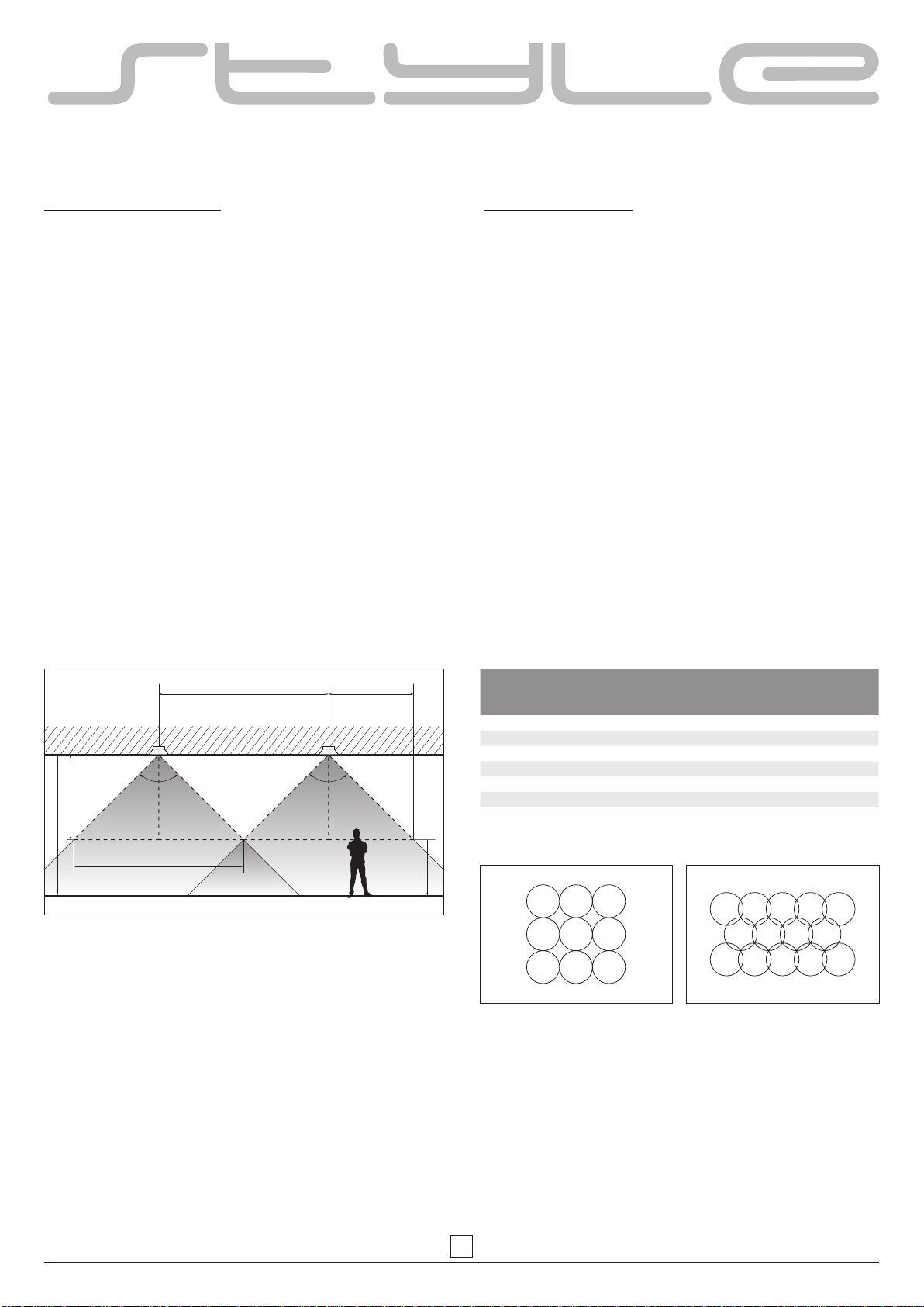
È possibile effettuare un calcolo rapido e approssimativo della
distanza "d" che separa i centri di due diffusori, conoscendo
l'angolo di dispersione "A" e l'altezza del soffitto "H":
d = 2*(H-1)*B dove "H" è l'altezza del soffitto espressa in metri, la
costante "1" è l'altezza del piano di ascolto di una persona seduta
e "B" è la tangente di A/2.
Dai dati espressi in tabella risulta evidente che, a parità di altezza
del soffitto "H", la distanza tra due diffusori aventi un angolo di
dispersione più ampio è maggiore, in quanto è più ampia la
superficie di sonorizzazione; di conseguenza viene richiesto, in tal
caso, un numero inferiore di diffusori.
WALL APPLICATIONS
If the architectural features of the room are not compatible with a
ceiling configuration or if a "wall" application is preferred, it is
essential to observe a few basic rules to obtain the best possible
sound distribution.
In order to maintain the listening point inside the direct signal area,
both surface mounted and external speakers, with power from 6 to
20W, should be installed at a height of between 2 and 2,5m. The
maximum distance between adjacent speakers must be no more
than 5 / 6 metres along the lenght of the room, which should be no
wider than 4 / 5 metres. For wider rooms, e.g. about 8 / 10 metres,
it is recommended to install speakers in an alternated pattern
along both the opposing walls in such a way as to provide
adequate coverage and maintain sound pressure at the most
constant possible level in the area in question.
A quick and approximate calculation can be made of distance "d",
which separates the centres of two speakers, when the angle of
emission "A" and height of the ceiling "H" is known:
d = 2*(H-1)*B, where "H" is the height of the ceiling expressed in
metres, constant "1" is the height of the listening surface of a
seated person and "B" is the tangent of "A/2".
From the above data it is evident that for the same ceiling height
"H", speakers with wider dispersion angles offer a larger sound
diffusion area and therefore a smaller number of speakers are
effectively needed.
GENERAL INFORMATION ON THE VARIOUS
METHODS OF INSTALLATION
4÷5 mt
5÷6 mt
12 mt
2÷2,5 mt
8÷10 mt
5÷6 mt 5÷6 mt
24 mt
2÷2,5 mt
9
INFORMAZIONI GENERALI SUI METODI
DI INSTALLAZIONE
GENERAL INFORMATION ON THE VARIOUS
METHODS OF INSTALLATION
APPLICAZIONI A SOFFITTO
In ambienti dotati di altezze adeguate, ci si può avvicinare a
questo standard ideale di riferimento attraverso l'applicazione di
altoparlanti dotati di ampia risposta ed angoli di emissione
costanti al variare della frequenza, disposti in configurazioni di
distribuzione a "soffitto" o a "pioggia". In questo modo si potrà
ottenere:
1-Massima uniformità di distribuzione sonora
2-Migliore intelligibilità dell'annuncio vocale
3-Qualità musicale costante
4-Minore presenza di riverberazioni e di onde stazionarie
nell'ambiente
5-Sorgente sempre a distanza costante dal punto di ascolto
6-Adeguata energia sonora anche al livello più basso
Una volta scelto il tipo di diffusore da installare, ed esaminati i
parametri che lo caratterizzano, in modo particolare il rapporto fra
l'angolo di emissione e la superficie dell'ambiente, è semplice
calcolarne il numero necessario per ottenere una distribuzione
costante e uniforme.
Il numero di diffusori si ricava dividendo la superficie dell'ambiente
espressa in mq., con quella del singolo diffusore nel punto di
ascolto.
CEILING APPLICATION
In environments offering suitable height, this ideal reference
standard can be approximated by using speakers with very wide
response and dispersion angles that remain unchanged at
different frequencies, arranged in a ceiling or shower type
configuration. This gives the following benefits:
1-Maximum sound distribution uniformity
2-Maximum speech intelligibility
3-Constant quality of music reproduction
4-Reduced presence of reverberation and stationary
waves in the environment
5-Sound source remains at a constant distance from the
listening position
6-Ample sound energy also at the lowest level
Once the required type of loudspeaker has been chosen and the
characteristic parameters considered ( particularly the
relationship between the dispersion angle and room surface area
), the number of units needed to obtain constant and uniform
sound diffusion can be easily calculated.
The number of speakers is calculated by dividing the floor area in
square metres by the area of coverage of each loudspeaker on the
listening plane.
2 x 2
ZONA
D'OMBRA
(H-1,5 mt)
1,5 mt
H
α α
Angolo di
dispersione
diffusore
Coefficiente
B
d con
H=3m
d con
H=3,5m
d con
H=4m
d con
H=4,5m
80 0,84 3,36 4,2 5,04 5,88
90 1,00 4 5 6 7
100 1,19 4,76 5,95 7,14 8,33
110 1,43 5,72 7,15 8,58 10,01
120 1,73 ,6 92 ,8 65 ,10 38 12,11
130 2,14 8,56 10,7 12,84 14,98
Disposizione diffusori per copertura 80% Disposizione diffusori per copertura 100%
Layout of speakers for 80% coverage Layout of speakers for 100% coverage
10

CODE 31561 # 280415
This manual suits for next models
5
Table of contents


