Sumec 5554-747 User manual

After-sales Service Guide
21" 212cc Snow blower
SAN: 0533201847ZB
Customer Model: 5554-747

2
CONTENTS
Specification 3
Main parts Location 3
BOM& Spare Parts List 5
Operating Instructions 5
Maintenance and Storage 13
FAQS 20

3
Specification
Main parts Location

4
PARTS LIST
Carefully remove the machine from its packaging and check that the following
parts are included:

5
BOM& Spare Parts List
See Appendix 1.
Operating Instructions
ASSEMBLY
IMPORTANT! THIS SNOWBLOWER IS SHIPPED WITHOUT OIL OR
GASOLINE IN THE ENGINE.
Your new snowblower has been assembled at the factory with the exception of
those parts left disassembled tor shipping purposes. All parts such as nuts,
washers, bolts, etc., necessary to complete the assembly have been placed in
the parts bag. To ensure safe and proper operation of your snowblower, all
parts and hardware you assemble must be tightened securely. Use the correct
tools as necessary to ensure proper tightness.
TO REMOVE SNOWBLOWER FROM CARTON
1. Remove loose parts included with snowblower.
2. Cut down two end corners of carton and lay end panel down flat.
3. Remove all packing materials except padding between upper and lower
handle and padding holding operator presence control bar to upper handle.
4. Roll snowblower out of carton and check carton thoroughly tor additional
loose parts.
ASSEMBLING THE UPPER HANDLE
1. Position the ends of the upper handle on the inside of the lower handle and
align the holes.
2. Insert the arc head bolt into the aligned holes, with the bolt heads on the
inside of the handle.
3. Install the handle knobs on the bolts (Fig. 1) and tighten the knobs securely.
4. Install and adjust the control cable (see Adjusting the Control Cable on
pg.6).
IMPORTANT: Ensure that the cable is routed on the innerside of the handle.
INSTALLING THE RECOIL STARTER HANDLE
Install the recoil starter handle in the rope guide as shown in Fig. 2.

6
INSTALLING THE DISCHARGE CHUTE
Install the discharge chute assembly as shown in Fig. 3.
Make sure the discharge chute rotation handle and discharge chute is in the
correct position, tighten 3 screws with the cross-head screwdriver.
ADJUSTING THE CONTROL CABLE
Checking the Control Cable
Before each use, check the control cable and adjust it if necessary.
ADJUSTING THE CONTROL CABLE FIGS. 4/S
1. Stop engine and wait for all moving parts to stop and for hot parts to cool.
2. Move plastic sleeve up to auger control lever.
3. Remove cable end from adjustment bracket.
4. Insert Z-hook into highest adjustment bracket hole reachable.
5. Feed cable end through the adjustment bracket.
IMPORTANT: When auger control lever is disengaged, there should be slight
slack in the cable and no tension.
6. Start engine and engage auger control lever to ensure proper operation.
7. Release auger control lever and ensure paddle rotation stops.

7
IMPORTANT: Cable tension should not be excessive.
8. Reposition sleeve over adjustment bracket.
CHECKING AND FILLING ENGINE OIL
CAUTION! The following procedures and adjustments must be performed
before the engine is started. Do not attempt to make any of these adjustments
while the engine is running.
CAUTION! To prevent engine damage, the engine is shipped without oil or
gas.
The engine must be filled with the correct grade of oil and gas before starting
the engine.
NOTE! Running the engine with a low oil level will cause engine damage. It is
recommend that high detergent, premium quality 4-stroke engine oil be used.
Using non-detergent oil can shorten the engine's service life, and using
2-stroke oil will damage the engine.
CAUTION! Always use high quality detergent oil classified SAE 5W-30 oil or
equivalent. Never use additives with recommended oil. To prolong the life of
the engine, it is important that the oil is changed after the first 5 hours of use.
NOTE! To check the engine oil level, stop engine and place the snowblower on
a level surface.
1. Remove the oil tiller dipstick and wipe oil from it with a clean cloth (Fig. 6).
2. Insert the dipstick into the oil tiller neck, twist to close (Fig. 7).
3. Remove the dipstick again and check the oil level: the oil level must be
between the lower limit mark and upper limit mark on the dipstick. The
recommended oil (SAE 5W-30 or equivalent). Do not overfill. Wipe away any
spilled oil (Fig. 8).

8
FILLING WITH ENGINE FUEL
1. Clean the area around the gas filler cap before removing the cap. Remove
the warning tag, and check the fuel level (Fig.9).
2. Refill the tank if the fuel level is low.
3. Refuel carefully to avoid overfilling or spilling fuel. There should be no fuel in
the filler neck.
4. Clean up any overflow or splashes of gas before starting the engine.
5. Tighten the filler cap after filling: finger tight only (Fig.10).
OPERATION
STARTING AND STOPPING THE ENGINE
The density of air at high altitude is lower than at sea level. Engine power is
reduced as the air mass and air-fuel ratio decrease. Engine power will be
reduced for every 3000'/914 m of elevation above sea level. This is a natural

9
trend and cannot be changed by adjusting the engine. At high altitudes
increased exhaust emissions can also result due to the increased enrichment
of the air-fuel ratio. Other high altitude issues can include hard starting,
increased fuel consumption and spark plug fouling. To alleviate high altitude
issues other than the natural power loss, we can provide a high altitude
carburetor main jet at an additional cost.
TO START THE ENGINE
1. Push the ignition key fully inward (Fig. 11).
2. Move the fuel valve lever to the "ON" position (Fig. 12).
To start a cold engine, move the choke lever to the choke closed position
(Fig.13).
3. Move choke lever depending "ON" unit's temperature:
To start a cold engine, move the choke lever to the choke closed position
(Fig.12).
To start a warm engine, leave the choke lever to the opened position (Fig. 13).
4. Move the throttle lever to full speed to start the engine (Fig. 13).
5. Use primer control depending on unit's temperature (Fig. 13):
To start a cold engine, prime 3-5 times (Fig. 13).
To start a warm engine, do not prime.
NOTE: Do not use the primer or the choke if the engine has been running and
is hot. Excessive priming may flood the engine and prevent it from starting.

10
ELECTRIC START
NOTE: Use only a UL-Listed, 16-gauge extension cord recommended for
outdoor use that is not longer than 50 '/15m.
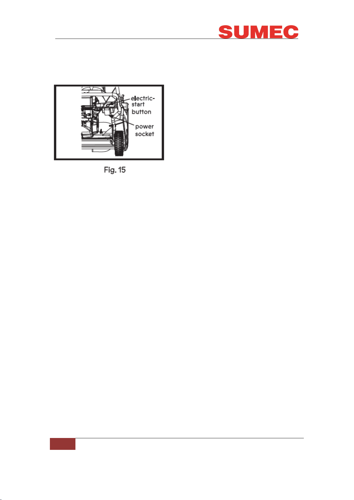
Connect an extension cord first to a power source and then to the power
socket of the machine, and press the electric-start button (Fig.15).
IMPORTANT: To prevent damaging the electric starter. Do not run the electric
starter more than 10 times at intervals of 5 seconds on, then 5 seconds off. If
the engine does not start after this series of attempts, allow the starter to cool
for at least 40 minutes before attempting to start it again. If the engine still does
not start after the second series of attempts, take the machine to an Authorized
Service Dealer for service. Once started, disconnect the plug from the power
supply and the starter.
RECOIL START
NOTE: If the recoil starter does not operate properly, it may be frozen. Thaw
out the starter before attempting to start the machine.
NOTE: If the engine fails to start after three pulls, repeat the process.
1. Pull the recoil start handle out approximately 4" to 6"/10 to 15 cm until you
feel a resistance and then start the engine with a sharp pull (Fig. 16)
2. Once the engine is running, put the starter rope into the rope guide (Fig. 16).
While the engine is running, move the choke lever gradually to the "RUN"
position;
STOP THE ENGINE
To stop the engine, pull the ignition key outward.
ENGAGING THE AUGER PADDLE
To engage the auger paddle, hold the auger control lever against the handle
(Fig. 17).

11
DISENGAGING THE AUGER PADDLE
To disengage the auger paddle, release the control bar (Fig. 18).
ADJUSTING THE DISCHARGE CHUTE AND CHUTE DEFLECTOR
Adjust the rotation handle right or left to change the thrower direction of the
snow (Fig.19). Move the chute deflector up or down to control discharge
distance. (Fig. 20).
CLEARING A CLOGGED DISCHARGE CHUTE
IMPORTANT: Hand contact with the rotating auger paddle inside the
discharge chute is the most common cause of injury associated with
snowblowers. Never use your hand to clean out the discharge chute.
CAUTION: Ensure the snowblower is completely shut off. Wait 10 seconds to

12
be sure the auger paddle has stopped rotating. Always use a tool to clean out
the chute, never use your hands.
SELF-PROPELLING THE SNOWBLOWER
Lift the machine handle until the wheels are just off the ground and the scraper
and auger paddle touch the ground. The machine will propel forward.
NOTE: By slightly varying lifting force on the handle, you can control the
forward speed of the machine. In heavy snow, push forward on the handle if
necessary, but let the machine work at its own pace. Do not lift the handle any
more than necessary, because the scraper will lift off the ground and snow will
escape behind the machine.
PREVENTING FREEZING AFTER USE
Keep the machine running for a few minutes after use to prevent freezing of
the auger paddle and moving parts. Stop the engine, wait for all moving parts
to stop, and remove ice and snow from the machine. Clean off any snow and
ice from the base of the chute. Rotate the discharge chute left and right to free
it from any ice buildup. With the ignition key in the off position, pull the recoil
starter handle several times to prevent the recoil starter from freezing up. In
snowy and cold conditions, some controls and moving parts may freeze. Do
not use excessive force when trying to operate frozen controls. If you have
difficulty operating any control or part, start the engine and let it run for a few
minutes.
OPERATING TIPS
Keep the area to be cleared free of all objects that the auger paddle could pick
up and eject. Keep all children and pets away from the operating area.
FOR OPERATION
Remove the snow as soon as possible after it falls. Overlap each swath to
ensure complete snow removal. Discharge the snow downwind whenever
possible.
LED LIGHT
The LED lights will turn on when you start the machine and turn off when you
stop the machine.

13
Maintenance and Storage
1. Secure unit so 1t will not tip over during maintenance.
2. Before cleaning, removing clogs or making any inspections, repairs, etc.,
disengage auger control lever, stop unit and engine, and allow moving parts to
stop and hot parts to cool.
3. Make sure the equipment is in safe working condition. Check hardware at
frequent intervals for proper tightness. If components are worn or damaged,
replace with manufacturer's recommended parts.
4. Do not change engine governor settings or overspeed engine.
5. Adjust and service as required. All motion of auger/impeller must stop
quickly when auger control lever is released.
6. Always maintain unit in safe operating condition. Damaged or worn out
muffler can cause fire or explosion.
7. Keep unit free of ice or other debris. Clean up oil or fuel spills.
8. Always keep protective structures, guards, and panels in good repair, in
place and securely fastened. Never modify or remove safety devices.
9. Never store the machine with fuel in the fuel tank inside a building where
ignition sources are present such as hot water heaters, space heaters or
clothes dryers. Allow the engine to cool before storing in any enclosure or
covering the unit.
10. Always refer to operator's manual for important details if the snow blower is
to be stored for an extended period.
11. Maintain or replace safety and instruction labels as necessary.
12. Run the machine a few minutes after throwing snow to prevent freeze-up of
the auger/ impeller.
WARNING: Before performing any maintenance or cleaning work, switch off
the engine and wait until the paddle has come to a stop.
CLEANING
GENERAL CLEANING
The snowblower should be cleaned thoroughly every time after it has been
used. Always clean your snowblower immediately after use. Do not allow snow
and other debris to become dry and hard on any of the snowblower surfaces.
Dried snow remnants and dirt may impair the snow clearing operation.
Check that the snow chute is free of any residual snow. Remove any such
residue. Check the underside of the snowblower and the blade mount. When

14
checking, tilt the snowblower onto its left side (opposite the oil filler neck).
NOTE: Before placing the snowblower on its side, fully drain the fuel tank using
a gas suction pump. Do not tilt the snowblower by more than 90 degrees.
MAINTENANCE OF THE SPARK PLUG (FIG. 21)
1. Once the engine has cooled, pull off the spark cover with a twist.
2. Remove the spark plug using a spark plug wrench (not supplied).
3. Clean the spark plug with a wire brush (not supplied).
4. Using a feeler gauge, set the gap to 0.7~0.8mm.
5. Install the spark plug carefully by hand, to avoid cross-threading.
6. After the spark plug is seated, tighten with the spark plug wrench to
compress the washer.
ADJUSTING THE CONTROL CABLE
Refer to Adjusting the Control Cable in assembly. See Adjusting the Control
Cable on page 6.
INSPECTING THE AUGER PADDLE
Service Interval: Yearly - Inspect the auger paddle and have the distributor or
local agent replace the auger paddle and scraper if necessary.
Inspect the auger paddle for wear. When a rotor blade edge has worn down to
the wear indicator hole, have the distributor or local agent replace the auger
paddle and the scraper (Fig. 22).
WARNING: If the wear indicator hole is intact, you don 't need to replace the
auger paddle. If the wear indicator hole is exposed, replace the auger paddle
and scraper.

15
REPLACING AUGER PADDLES
Replace auger paddles when paddles have worn completely through wear
indicator holes (Fig. 22).
IMPORTANT: ALWAYS replace paddles in pairs. DO NOT replace only one
paddle.
REMOVING AUGER PADDLES
1. Stop engine and wait for all moving parts to stop and for hot parts to cool.
2. Disconnect spark plug wire and turn fuel valve to off position (Fig. 23).
3. Tip unit back onto handlebar.
NOTICE: DO NOT tip beyond handlebar bend or oil may leak from engine.
4. Remove hardware retaining paddles to centre plate and side plates. Discard
all parts.
IMPORTANT: DO NOT remove centre plate.

16
INSTALLING AUGER PADDLES
1. Install spacers into paddle holes. (Figs. 24-26).
IMPORTANT: Install new paddles so wear indicator holes are positioned on
the right side of unit.
INSPECTING THE AUGER PADDLE
1. Secure each paddle to side plates with four hex bolts, four flat steel washers
and four flange nuts.
2. Secure each paddle to centre plate with two hex bolts and two flange nuts.
3. Torque paddle hardware to 5.6 N m - 10.2 N m 50 lb per inch to 90 lb per
inch. DO NOT overtighten.
4. Rotate auger paddles by hand to ensure paddles are secure and do not
interfere with housing.
5. Return unit to upright position.
6. Remove slack from auger cable. See Adjusting Control Cable on page 14.
7. Reconnect spark plug wire and turn fuel valve to the on position.
DRIVE BELT
REMOVING THE DRIVE BELT
1. Stop engine and wait for all moving parts to stop and for hot parts to cool.
2. Disconnect spark plug wire.
3. Remove belt cover hardware and remove cover. Retain all parts (Fig. 27).
4. Disconnect extension spring from idler arm (Fig. 28).
5. Remove belt from drive sheave, idler sheave and engine sheave.

17
INSTALLING DRIVE BELT
1. Install new belt around engine sheave and align with drive and idler sheaves
(Fig 29).
2. Reinstall extension spring onto idler arm.
IMPORTANT: Ensure belt has tension and is aligned in all sheaves.
3. Reinstall belt cover and secure with original hardware.
4. Reconnect spark plug wire.
REPLACING SCRAPER BLADE
Replace scraper blade if damaged, completely worn through, or with every
paddle replacement.
REMOVING SCRAPER BLADE
1. Stop engine and wait for all moving parts to stop and for hot parts to cool.
2. Tip unit back onto handlebar. (Fig. 23)
NOTICE: DO NOT tip beyond bend or oil may leak from engine (Fig. 30).

18
3. Disconnect spring hooks from scraper blade, remove from unit and discard.
4. Using a wrench, hold pivot rod stationary and remove hardware retaining
pivot rod and blade. Retain hardware.
5. Remove pivot rod from scraper blade and discard blade (Fig. 31).
INSTALLING SCRAPER BLADE
1. Insert pivot rod through new scraper blade.
IMPORTANT: Reinstall pivot rod so wrench flats are positioned toward the
right side of unit (Fig 32).
2. Secure scraper blade assembly to housing with original hardware (Fig. 33).
3. Install spring hooks to frame and around scraper blade. Make sure blade
has tension.
STORING THE SNOWBLOWER FOR SHORT PERIODS
The snowblower can be stored for short periods of time (less than 15 days)
without performing any storage maintenance. Before placing the snowblower
into storage always carry out the following:
1. Allow the engine to fully cool.
2. Clean all debris from the snowblower deck.

19
3. Store the snowblower on flat and level surface.
4. Store in a safe place which is not accessible by children or people who are
not familiar with operating it.
STORING THE SNOWBLOWER FOR EXTENDED PERIODS
If the snowblower is to be placed into storage for more than 15 days, storage
maintenance must be performed on the snowblower. If the following steps are
not carried out, when you next operate the snowblower it may not start
correctly and may need to be serviced.
1. Empty the gas tank with a "gas extraction pump" if available.
2. Start the engine and let it run until any remaining gas has been used up.
3. Change the oil at the end of every season. To do so, remove the used
engine oil from a warm engine and refill with fresh oil.
4. Clean the cooling fins of the cylinder and the housing.
5. Be sure to clean the entire machine to protect the paint.
6. Store the machine in a well-ventilated place.

20
FAQS
Disconnect the machine from the power source before making any
repairs.
This manual suits for next models
1
Table of contents
Other Sumec Snow Blower manuals