DUUN TFP250 User manual

TFP250 Instruction manual
Serial number: from 190001
Duun Industrier as
7630 Åsen, Norway
www.duun.no

2
Congratulations on your Duun TFP250 snow blower.
All Duun tractor operated machines have been engineered and tested in close cooperation with
representative users to produce functionally safe and user-friendly machines.
Please read this instruction manual before using the machine.
Good luck!
Machine identification
Serial number and manufacturer are indicated on badge (A)
Register serial number and delivery time as indicated.
Always specify serial number when requesting service for the machine.
The machine is CE-marked (B), opposite side of drawing. This marking confirms that the machine
has been manufactured in conformity with EU Directive Machinery.
Serial number
Time of delivery (month/year)

3
CONTENT
MACHINE INDETIFICATION 2
SERIAL NUMBER AND MANUFACTURER ARE SPECIFIED ON BADGE (A) 2
SAFETY 4
WARRANTY TERMS 7
TECHNICAL DATA 8
SPECIFICATIONS 9
PREPARATION FOR USE 10
CONNECTION 11
FRONT MOUNTING AND REVERSING 12
GEARBOX 13
SERVICE AND MAINTENANCE 14
SHEAR - BOLT COUPLINGS 16
OPERATIONAL RISKS 16
PRACTICAL USE 16
DISCONNECTION 16
MOUNTING INSTRUCTIONS HYDRAULIC SIDE EXTENSION 17
DECLARATION OF CONFORMITY 18

4
SAFETY
All operators, mechanics and the owner must always work carefully with agricultural machinery.
Read and observe safety instructions in this instruction book.
Be particularly aware of warning signs with this symbol, it marks
measures that must be carried out in order to avoid accidents. The
symbol appears in the instruction manual and on warning signs on the
machine.
Instruction manual
All operators, mechanics and the owner must be well
acquainted with the instruction in this instruction manual
before the machine is taken into use.
The safety of the surroundings
Be very careful when other people or animals are near the
machine or tractor. Never start the machine when there are
people or animals close to it, also never stand between the
tractor wheels and the machine!
Safe connection and use
Do not allow anyone to stay between the machine and the
tractor when the machine is connected to the tractor. The
same applies during the use of the machine. Make sure that
the connection is carried out in a safe manner. By
automatically connecting with a triangle or HMV, the
hydraulic hoses are connected before the start of work.
Connecting with draw bolts, secure the drawbar connection
with lunch pins before the hydraulic connection and start
operation.
Safety in case of interruptions and maintenance
Remember always to stop the tractor’s engine and remove
the ignition key before you lubricate, adjust, clean, or carry
out repairs. This is to secure that the tractor does not start
before you have completed the operation.

5
Power transmission shaft
The tractor is disengaged and the handbrake is applied
before the shaft is connected to the tractor's PTO.
The maximum power output speed is 540 rpm. The drive
shafts are always to be equipped with original protection
covers.
Damaged and worn covers are to be replaced
immediately!
Make sure that all covers for the shaft are in good condition
and correctly fitted. Never start the machine when this is not
in order. The locking chains for the plastic covers are
always to be fixed to the appropriate brackets in order to
prevent the covers to rotate. The covers must be lubricated
according to the specified interval.
Rotating parts –high risk of injury
The rotating parts of the machine can cause major damage
to body parts that come into contact with them. Do not allow
anybody to stay in the work area when a machine is in
operation.
Hydraulic high fluid pressure
Be careful when you work with hydraulics. Wear eye
protection and gloves. Hydraulic oil under high pressure
may penetrate the skin and cause serious infections. See a
doctor if you have sustained an injury. Make sure no one is
close by when performing hydraulic functions.
Rotating parts –risk of crushing
Case covers and moving parts are preferably marked in
yellow.
All covers must always be used except when necessary
maintenance, and always with a stopped engine as
mentioned in safety in case of interruptions and
maintenance. Pay special attention to clamping risk at
points marked for this. Avoid hydraulic movement of the
ejection spout when there are people nearby.
Never drive with open covers for chains and sprockets.
Chains and sprockets can cause major damage to body
parts that come into contact with them during operation.
Clamping risk when adjusting
When adjusting the support wheels, make sure that you do
not stand with your feet under the wear steel.

6
Always lower the machine to safety rest at ground level when it needs to be parked.
Working on the machine the tractor engine must be stopped and the power shaft set to neutral.
Never work under a lifted device unless it is mechanically secured against coming down.
Before startup after servicing make sure all tools have been removed and brought into place.
Do not work in clothing that can be retracted into moving parts of the machine (e.g. scarves, wide
coats).
Wear hearing protection if the machine has annoying or damaging noise levels.
Before the machine is raised or lowered, make sure that no person is near or touching the
machine.
If warning signs are removed during repairs or service, new signs should be installed
immediately!

7
Warranty terms
Duun TFP250 has 12 months guarantee against defects in materials and workmanship.
Parts that are not originally manufactured by Duun Industrier as, for example, wheels, hydraulic
parts, etc. are subject to these suppliers’ guarantees and terms.
In cases where a repair is considered to be covered by the guarantee, the representative must
inform the supplier’s representatives that the repair is intended executed based on the guarantee.
In this context, the following information must be recorded:
•Product name
•The product’s serial no. (see the machine identification)
•Date of sale
•The product owner’s address, telephone no.
In case of such a repair, the supplier is presented with a claim within 3 weeks after the repair date.
Replaced parts are to be kept until a decision has been made with reference to the claim and the
replaced parts are to be forwarded to Duun Industrier as for assessment if so required.
As the employment of the product is beyond our control, we may only guarantee the quality and
do not accept liability for the product's general performance.
Duun Industrier as reserves the right to modify the design and specifications and/or make
alterations and improvements without notification.
What is not included in the guarantee:
•The guarantee does not cover economic loss as a consequence of interruptions.
•The guarantee does not cover consequential loss due to defects.
•The guarantee does not cover defects or damage caused by misuse and uses that are not
in accordance with the instruction manual’s specifications and guidelines.

8
Technical data

9
Features:
TFP250
Weight
1550 kg
Width
2500 mm
Working width with side extension
right
2630 mm
Working width with side extension left
2764 mm
Inner width
2360 mm
Inner height
1107 mm
Diameter of feed screw
650 mm
Height to top of screw
711 mm
Diameter of fan
900 mm
Power requirement 540 rpm
120-300 hk
Operation of fan
Mechanical from PTO
Operation of feed screw
Chain operation
Bolt fasteners connections are
standard
Yes
Number of blades in the ejector fan
4
Hydraulically operated outlet flap
Standard
Breakdown flap
Standard
Removable sidewalls
Standard
Diameter of wear steel
200x12x1215 mm og 200x12x1113 mm.
Hole spacing for wear steel
305 mm
Bolts wear steel
16x45 quality 8.8
All specifications are approximate
values.
Asseccories:
Hydraulic side extension right with
shock valve (height 1500 mm, width
50-190 mm)
125319101
Hydraulic side extension right with
shock valve (height 1500 mm, width
50-190 mm)
125319105
Side extension left (height 1500 mm,
width 130 mm)
125319106
Side extension upper right (for use
without side walls on the snow blower)
125319107
Side extension upper left (for use
without side walls on the snow blower)
125319108
Additional power transmission shaft
front/reverse/drive
2962158
Support wheel pair
1252017
Ice rake steel for skid pad, set
125309014
Control plate in spout
125319110

10
Preparation for use
Adjustment of skid pads
The snow blower is placed on a level surface and the skid pads are adjusted so that the wear
steels on both sides + the infeed steel in front of the fan housing have clearance above ground
level. Too small distance here will cause abnormal wear on both wear steel and feed steel.
Power transmission shafts
The snow blower has a power transmission shaft between tractor and snow blower. It also has a
power transmission shaft between the gearbox and the feeder screw chain.
Please lubricate the power transmission shaft before use.
The power transmission shafts are maintained and used according to the attached instruction
manual.
Power transmission shaft from tractor
Make sure that the PTO shaft is of sufficient length. After any length adjustment, the profile pipes
in the shaft must overlap each other by half the pipe length. Any cutting of the shaft is carried out
accordance to the instructions for this –the cut point is chamfered inside and out, and the profile
tubes are lubricated with grease. Too short a telescopic length on the axle entails a risk of
overloading the tractor's power take-off and the snow blower's bearings. On the other hand, the
shaft must not be too long so that it presses on the front and rear bearings and destroys
them.
The shear bolt coupling on the shaft is mounted against the implement. The coupling has a
capacity of 4180 nm and in the event of a break in this, a hexagonal screw dim 12 mm qval 8.8
must be used as a breaking pin. The locking chains for the protective covers must always be
attached to suitable fasteners to prevent the covers from rotating.
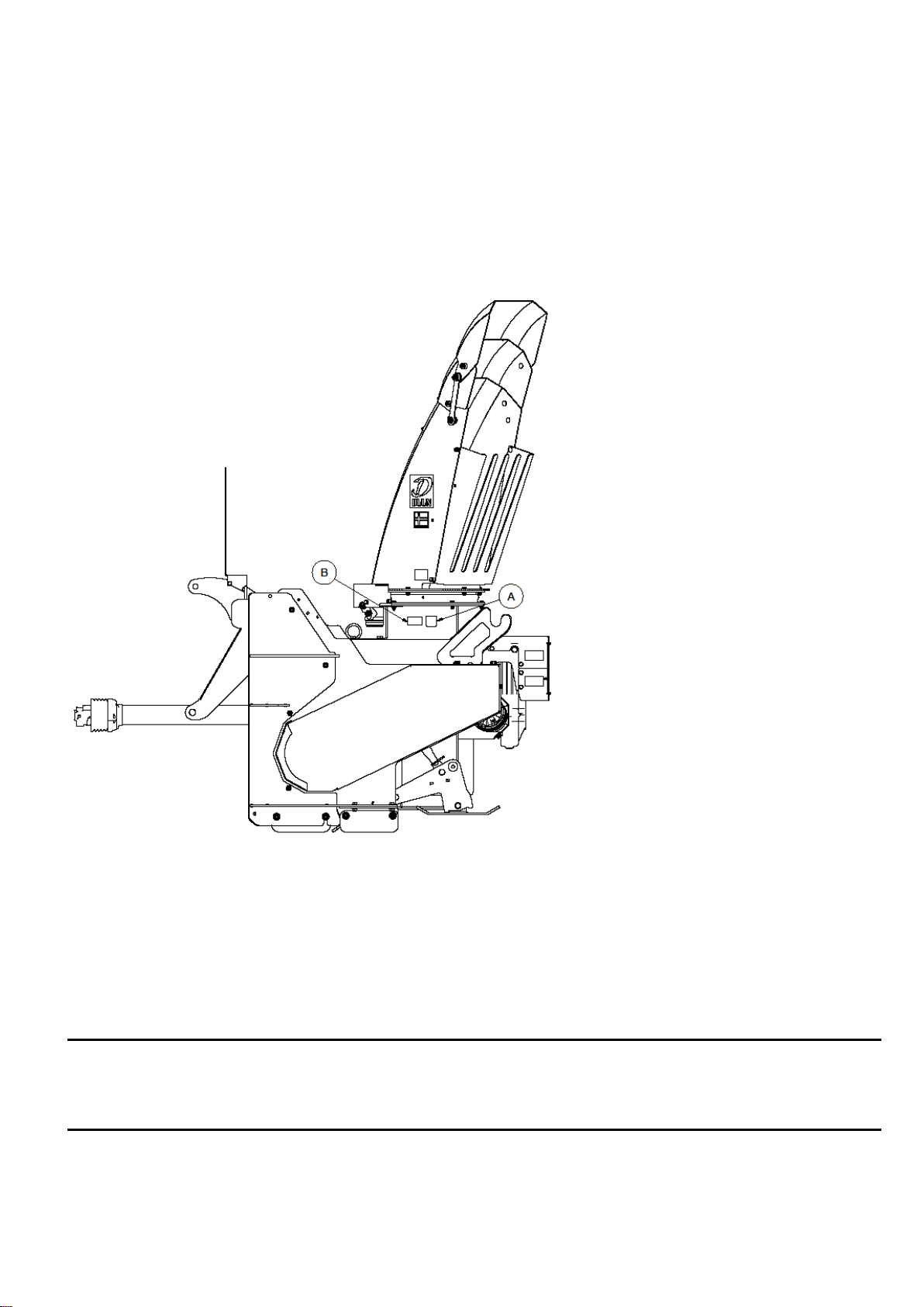
Power transmission shaft between gearbox and chain drive for the feeder screw
It has been fully adapted and is mounted on the snow blower.
In case of a break in the shear bolt connection, sext. screw dim 10 mm qval 8.8 is used.
Save control of greasing (lubrication)
Check that the warehouses (front and back) are lubricated. Lack of lubrication entails a risk of
breakdown. Also, be careful not to "over-lubricate" the bearings as this entails the risk of heat
build-up and overheating in the bearing itself. In the case of too little lubrication, water can
penetrate (infiltrate) the bearings.
Lubrication of ball bearing
Check that this is lubricated and make sure it is lubricated before use if this is not the case. Too
little lubrication causes abnormal wear on the gears and chain.
Chain drive feeder screw
The feeder screw is driven by a chain that must be lubricated with thin engine oil.
Protection of hydraulic hoses
Check the hose connections and that they are not stretched or cut during use. Tighten loose hose
connections and secure/fasten the advance of the fittings.
Failure to secure hydraulic hoses can lead to leaks and consequential damage to tractors and
components.

11
Connection
Stabilization struts/support struts on tractors must be used.
This is to ensure that the snow blower does not get uncontrolled lateral movements while
driving –i.e. goes in the same direction as the tractor all the times.
Make sure no one is standing between the tractor and the machine during connection. Back the
tractor up to the snow blower and stop the engine before the lifting arms are mounted in the three-
point hitch.
Hydraulic hoses installation. At the same time, check that all hoses are tight and undamaged
before starting hydraulic functions. When the tractor engine is stopped, you should ensure that
there is no pressure in the hoses by activating the tractor's hydraulic valves.
Pay special attention to the dangers of hydraulic oil under pressure.
Install the power transmission shaft on the PTO with the shear - bolt coupling against the snow
blower. A safety chain is attached to the snow blower to prevent the rotation of protective covers.
The power transmission shaft must always have a shear bolt coupling max 4180 nm.
Make sure that the protective covers for the power transmission shaft are unaffected(undamaged)
and replace them if they are damaged.
Before connecting the power transmission shaft, secure the following points.
Make sure that the shaft's protective tubes are unaffected(undamaged) and that the two halves of
the shaft fit freely into each other. The length of the power transmission shafts must be adjusted
carefully, if it is too long it can damage the bearing in the tractor's PTO or the snow blower’s
bearings. Also ensure good lubrication of the profile pipes. See also the instruction manual for the
power transmission shaft.
Check that the power transmission shaft can be rotated by hand to ensure that it is not buckling
anywhere.
Check that the power transmission shaft will not be tensioned when the machine is lifted to max.
or min. height. Driving on very hilly relief, a rear-mounted snow blower can work lower or higher
than the tractor itself. Please also note that the angle of the axle can be too large when using very
short axles - contact the supplier - importer.

12
Front mounting and reversing
To use snow blower for front
mounting or when reversing,
the snow blower must
change the direction of
travel. Changing the direction
of travel is done by turning
three point linkage to the
opposite side of the snow
blower. Loosen up two
screws that hold the three
point linkage and use the
tractor to turn it around on
the opposite side.
Remember to put screws
back and secure them.
The snow blower is prepared
for reversing and front
mounting.
The top pin marked with
1000 rpm is for a front drive.
The bottom pin marked with
540 rpm is for reversing.

13
Gearbox
Oil quantity: 5.5 litres
Recommended oil: Gearbox oil Mereta 220 synthetic oil (Statoil), Esso Syntetic EP150 and
Mobilgear 632.
Other oil must stay standard SAE90EP or GL5.
Mereta 220 - 1 liter has item no. 531 0 110.
Check the oil level after 50 operating hours or after each season by loosening the level screw
marked B, as illustrated in the sketch (oil should then leak out at a sufficient level).
If the oil level requires refilling, refill with the same type of oil.
The first oil change is recommended after 50 hours of use, and then every second season or after
500 operating hours –if 500 operating hours occur before the end of the 2nd season, oil change
with Mereta 220 is carried out as prescribed.
It is an advisable to change the oil when the gearbox is warm.
A- Air plug / filler plug
B- Oil level plug
C- Drain plug
It is very important to fill the gearbox with the correct amount of oil. Too much oil will lead
to a higher operating temperature and risk of breakdown.

14
Service and maintenance

15
Before cleaning, lubricating, repairing or adjusting the machine, stop the engine and activate the
handbrake, and remove the key during work. Close the safety crane on the snow blower that
closes the oil on the operation of the feeder screw.
Pay special attention to safety during maintenance work, park the machine in according with
specified safety rules.
Inspection after screw connections
Screws - nuts - fittings and bolts on the machine should be re-tensioned after two hours of
operation. All moving parts should be lubricated with grease.
The ejector spout's swivel is exposed to both cold and heavy wear - therefore use cold-resistant
grease that can handle up to -40 degrees.
Wear steel and skid pads are exposed to heavy wear - check and carry out the replacement or
reversal of wear steel before damage occurs to the hull itself and mounting brackets.
Remove snow after use so that icing does not cause any problems at start-up later.
To extend the life of the machine, cleaning after use is recommended. Do not flush water directly
into the bearing. For long-term storage, it is recommended to lubricate the machine in acid-free oil.
Interval of lubrication and grease quality
Bearing for the front fan (1 pcs.)
Interval: Every 100 hours and when parking in the spring.
Avoid pushing in too much grease as this can cause sealing rings to squeeze
out + contribute to overheating of the entire bearing.
The recommended amount of 7-8 grams per time.
Bearing for the feed screw (2 pcs.)
Interval: Every 100 hours and when parking in the spring.
Avoid pushing in too much grease as this can cause sealing rings to squeeze
out + contribute to overheating of the entire bearing.
Recommended amount of 7-8 grams per time.
Bearing for the operation of the feeder screw (2 pcs.)
Interval: Every 100 hours and when parking in the spring.
Avoid pushing in too much grease as this can cause sealing rings to squeeze
out + contribute to overheating of the entire bearing.
The recommended amount of 7-8 grams per time.
Expiration spout for ball bearing
Interval: Every 50 hours. Use low temperature grease Statoil uniwai LIX 42 or equivalent.
Sprocket on outlet spout
Interval: When needed.
Power transmission shafts –universal joint + telescopic tube
Interval: Every 8 –10 operating hour.
Maintained according to the attached instruction manual. Please contact the supplier if this is
missing.
Grease quality: Universal grease of good quality.

16
Shear - bolt couplings
Remember to lower the machine, stop the tractor's engine, disengage the PTO and close the
cutter's safety tap before fitting a new cutting bolt.
- Power transmission shaft against tractor bolt M12x60 qual. 8.8.
- Power transmission shaft operation feeder screw bolt M10x50 qual. 8.8.
NB! It is very important that the breaking bolts have a smooth contact surface at the
breaking point, i.e. to avoid that the threaded part is included in the breaking point since
this significantly weakens the breaking strength.
Operational risks
It is the driver's responsibility not to expose himself or others to danger during the use of the snow
blower. Attention should be paid to people and animals located near the machine. Since other
objects occur in the snow (rocks and similar things), the throwing route must be set so that the
draft snow would not be danger to other road users. Since there are more objects in the snow
(stones), the ejection nozzle must be adjusted so that the ejected snow does not pose a danger to
other road users.
No one should ever stand on the machine while it is driving or moving. Protective covers must
always be on when it is used.
Practical use
The Norwegian Labor Inspection Authority has listed snow blowers among machines that must be
used with particular care and must therefore not be operated by people without documented
training. The user must have a driving license for a tractor (aged 16) and have a certificate that he
has received training in the use of the machine/tool.
The machine requires skilled operation, the user manual must be read before connecting to the
tractor and putting it into operation, even if the user had previous experience with a similar
machine –this is for user’s safety.
The top brace is adjusted so that the snow blower is parallel to the ground in working position.
Skid pads must always be used and adjusted according to the instructions in user manual.
Optional use of support wheels.
The direct-coupled PTO must not be switched on at high rpm.
Driving in packed snow, it is important to keep the rpm. high from the time you enter the snow until
the fan is empty.
Disconnection
This happens in the reverse order of connection.
The tractor's PTO must be disconnected when working with the machine and the PTO shaft.
Place the machine on the even ground.
Disconnect hydraulic hoses.
Disconnect the power transmission shaft and hang it on a hook attachment.
Locking bolts for drawbars are released.
Now the machine is disconnected and can be left.

17
Mounting instruction hydraulic side extension
A: The bracket for cylinder must be mounted as in the illustration.
B: The protrusion on the safety valve is adjusted to 4.7mm from the nut to end of umbra screw.
C: 2 pcs. holes threaded M10.

18
Table of contents
Other DUUN Snow Blower manuals