Superscope PAC750 User manual

1
R
Professional
CD/Cassette/Mixer/
System
PAC750
Owners Manual
LEVEL
10
9
8
7
6
5
4
3
2
1
0
TEMPO
KEY
UP
10
9
8
7
6
5
4
3
2
1
0
EJECT
REC
AUTO DUBB
DOWN
STOP
SINGLE
PITCH
OPEN/CLOSE
ON
AUTO LEVEL
OFF
PLAY PLAY
REC
BALANCE
PLAY/PAUSE
4
MIC/LINE
321
AUX
VOLUME
EQ
BALANCE
PLAY
HIGH
LOW
MID
STOP
RESET
A-B
TIME
L
DOLBY NR
CD
TAPE
REPEAT
R
OFF B C
PAC770
PROGRAM
MEMO
DOLBY B-C NR HX PRO
2
STEREO
PRESET
REM
TOTAL
TRACK
REPEAT1
PROGRAM
AUTO
kHz
MEMO
A-B
MEMO
HX
DUBB
NR
DOLBY
MHz
PRO
BC
H-SP
19181716151413121110
987654321
+3
0
-3-6
-10-15-20
R
L
20
HP LEVEL
HEADPHONE
HP SELECT
POWER
SYSTEM
AUXCD TAPE
MIC/LINE
TAPE
CD
DUCKING
REDUCTION
GAIN
-
∞
-15
CD+TAPE+AUX
OFF
ON
AUTO
VOICE
MIC/LINE
AUTO
AUTOMATIC TAPE SELECT SYSTEM
QUICK REVERSE
Professional
CD/Cassette/Mixer/
Amplifier System
PAC770

2
CAUTION
RISK OF ELECTRIC SHOCK
DO NOT OPEN
CAUTION: TO REDUCE THE RISK OF ELECTRIC SHOCK,
DO NOT REMOVE COVER (OR BACK)
NO USER-SERVICEABLE PARTS INSIDE
REFER SERVICING TO QUALIFIED SERVICE PERSONNEL
The lightning flash with arrowhead symbol, within
an equilateral triangle, is intended to alert the user
to the presence of uninsulated “dangerous voltage”
within the product’s enclosure that may be of suffi-
cient magnitude to constitute a risk of electric shock
to persons.
The exclamation point within an equilateral triangle
is intended to alert the user to the presence of
important operating and maintenance (servicing)
instructions in the literature accompanying the
appliance.
WARNING
TO REDUCE THE RISK OF FIRE OR ELECTRIC SHOCK,
DO NOT EXPOSE THIS APPLIANCE TO RAIN OR MOISTURE.
This Class B digital apparatus meets all
requirements of the Canadian Interference-
Causing Equipment Regulations.
Cet appareil numérique de la Classe B respecte
toutes les exigences du Règlement sur le matérier
brouilleur du Canada.
NOTE:
This equipment has been tested and found to comply
with the limits for a Class B digital device, pursuant to
Part 15 of the FCC Rules. These limits are designed to
provide reasonable protection against harmful interfer-
ence in a residential installation. This equipment gener-
ates, uses and can radiate radio frequency energy and,
if not installed and used in accordance with the instruc-
tions, may cause harmful interference to radio communi-
cations. However, there is no guarantee that interference
will not occur in a particular installation. If this equipment
does cause harmful interference to radio or television
reception, which can be determined by turning the equip-
ment off and on, the user is encouraged to try to correct
the interference by one or more of the following mea-
sures:
– Reorient or relocate the receiving antenna.
– Increase the separation between the equipment and
receiver.
– Connect the equipment into an outlet on a circuit
different from that to which the receiver is connected.
– Consult the dealer or an experienced radio/TV techni-
cian for help.
NOTE:Changes or modifications may cause this unit
to fail to comply with Part 15 of the FCC Rules and may
void the user's authority to operate the equipment.

3
SAFETY
INSTRUCTIONS
READ BEFORE OPERATING EQUIPMENT
This product was designed and manufactured to meet strict
quality and safety standards. There are, however, some instal-
lation and operation precautions which you should be particu-
larly aware of.
1. Read Instructions — All the safety and operating instruc-
tions should be read before the appliance is operated.
2. Retain Instructions — The safety and operating instruc-
tions should be retained for future reference.
3. Heed Warnings — All warnings on the appliance and in
the operating instructions should be adhered to.
4. Follow Instructions — All operating and use instructions
should be followed.
5. Water and Moisture — The appliance should not be used
near water — for example, near a bathtub, wash-bowl,
kitchen sink, laundry tub, in a wet basement, or near a
swimming pool, etc.
6. Carts and Stands — The appliance should be used only
with a cart or stand that is recommended by the manufac-
turer.
7. An appliance and cart combination should be moved with
care. Quick stops, excessive force, and uneven surfaces
may cause the appliance and cart combination to over-
turn.
8. Wall or Ceiling Mounting — The appliance should be
mounted to a wall or ceiling only as recommended by the
manufacturer.
9. Ventilation — The appliance should be situated so that its
location or position does not interfere with its proper venti-
lation. For example, the appliance should not be situated
on a bed, sofa, rug, or similar surface that may block the
ventilation openings; or, placed in a built-in installation,
such as a bookcase or cabinet that may impede the flow
of air through the ventilation openings.
10. Heat — The appliance should be situated away from heat
sources such as radiators, heat registers, stoves, or other
appliances (including amplifiers) that produce heat.
11. Power Sources — The appliance should be connected to
a power supply only of the type described in the operating
instructions or as marked on the appliance.
12. Grounding or Polarization — The precautions that should
be taken so that the grounding or polarization means of an
appliance is not defeated.
13. Power-Cord Protection — Power-supply cords should be
routed so that they are not likely to be walked on or pinched
by items placed upon or against them, paying particular at-
tention to cords at plugs, convenience receptacles, and the
point where they exit from the appliance.
14. Cleaning — The appliance should be cleaned only as rec-
ommended by the manufacturer.
15. Nonuse Periods — The power cord of the appliance should
be unplugged from the outlet when left unused for a long
period of time.
16. Object and Liquid Entry — Care should be taken so that
objects do not fall and liquids are not spilled into the enclo-
sure through openings.
17. Damage Requiring Service — The appliance should be
serviced by qualified service personnel when:
A. The power-supply cord or the plug has been damaged;
or
B. Objects have fallen, or liquid has spilled into the appli-
ance; or
C. The appliance has been exposed to rain; or
D. The appliance does not appear to operate normally or
exhibits a marked change in performance; or
E. The appliance has been dropped, or the enclosure
damaged.
18. Servicing — The user should not attempt to service the
appliance beyond that described in the operating instruc-
tions. All other servicing should be referred to qualified ser-
vice personnel.

4
LASER SAFETY
This unit employs a laser. Only a qualified service
person should remove the cover or attempt to service
this device, due to possible eye injury.
CAUTION :
USE OF CONTROLS OR ADJUSTMENTS
OR PERFORMANCE OF PROCEDURE
OTHER THAN THOSE SPECIFIED HEREIN
MAY RESULT IN HAZARDOUS RADIATION
EXPOSURE.

ENGLISH
7
TABLE OF CONTENTS
FRONT AND REAR PANEL DRAWINGS ....................................................................... 5
SPECIFICATIONS ........................................................................................................... 6
INTRODUCTION ............................................................................................................. 8
PRECAUTIONS............................................................................................................... 8
FEATURES...................................................................................................................... 8
REAR PANEL CONNECTIONS ...................................................................................... 9
FRONT PANEL FEATURES ......................................................................................... 10
OPERATION.................................................................................................................. 13
MIXER OPERATION ..................................................................................................... 13
The Mixer In Relation To The Tape Deck ............................................................. 13
CASSETTE DECK OPERATION................................................................................... 13
Cassette Tape Playback ....................................................................................... 13
Searching For Tracks ............................................................................................ 13
Rewind & Fast Forward......................................................................................... 13
Cassette Tape Record .......................................................................................... 13
Erasure Of Tape.................................................................................................... 13
To Protect Valuable Recordings ........................................................................... 13
Auto Tape Selector ............................................................................................... 13
CD PLAYER OPERATION ............................................................................................ 14
CD Playback ......................................................................................................... 14
Selecting The Playback Track............................................................................... 14
A-B Repeat............................................................................................................ 14
Programming Playback Tracks ............................................................................. 14
Tempo Control ...................................................................................................... 14
Key Control ........................................................................................................... 15
CD-RW/CD-R Playback ........................................................................................ 15
CD TO TAPE DUBBING ................................................................................................ 15
Manual Record Level Dubbing .............................................................................. 15
Automatic Record Level Dubbing.......................................................................... 15
TROUBLESHOOTING................................................................................................... 16
REPAIRS ....................................................................................................................... 16
CLEANING OF EXTERIOR SURFACES ...................................................................... 16
COMPACT DISC CARE ................................................................................................ 17
CASSETTE TAPE CARE .............................................................................................. 17
BASIC HOOKUP ........................................................................................................... 51
PAC750 ................................................................................................................. 51
PAC770 ................................................................................................................. 52

5
S
U
F
E
PUSHPUSH
NEUTRIK NEUTRIK NEUTRIK
PUSH
NEUTRIK
PUSH
ONOFF
FILTER
MPX
ONOFF
SENSITIVITIYSENSITIVITIY SENSITIVITIYSENSITIVITIY
48V 48V48V48V
OFF ON
PHANTOM PHANTOM
ONOFF
PHANTOM
OFF ON
L
R
R
L
ONOFF
AUX
IN
OUT
REMOTE
INPUT 2 INPUT 1INPUT 3
R
L
OUT
PHANTOM
EFFECT
RLR
LINE
HIGH
LOW
MIC
LINE
MIC
LINE
MIC
LOW
HIGH
LINE
LOW
MIC
LOW
HIGHHIGH
MIC/LINE
INPUT 4
EQ EQ
IN IN
HIGH
R
EQ
PAN
LOW
LLRL
EQ
PAN PANPAN
R
L
OUT
CD
TAPE
OUT
NEUTRIK
OUT
BALANCED
R
L
OUT
UNBALANCED
L
SYSTEM
R
-
+
1
GND
2
3
-
+
2
GND
1
3
ABCDE H
IML
COMMON
HOT COLD
HIGH
LOW
HIGH
LOW
HIGH
LOW
NEUTRIK
N
PUSHPUSHPUSHPUSH
NEUTRIK NEUTRIK NEUTRIKNEUTRIK
ONOFF
FILTER
MPX
BRIDGE
MONO
ONOFF
SENSITIVITIYSENSITIVITIY SENSITIVITIYSENSITIVITIY
48V 48V48V48V
-
+
(8ΩMIN)
(4ΩMIN)
TO SPEAKER
R AND L
CONNECT
MONO BRIDGE ON:
SPEAKER
OFF ON
PHANTOM
OFF
PHANTOM
ON
ON
OFF
PHANTOM
OFF ON
R
LL
R
R
L
ONOFF
LR
SPEAKER
L
R
(4ΩMIN)
++
SELECT
SPEAKER
AUX
IN
OUT
REMOTE
OUT
INPUT 2 INPUT 1INPUT 3
R
L
OUT
PHANTOM
EFFECT
CD
TAPE
PRE-AMP
RLR
LINE
HIGH
LOW
MIC
LINE
MIC
LINE
MIC
LOW
HIGH
LINE
LOW
MIC
LOW
HIGHHIGH
MIC/LINE
INPUT 4
EQ EQ
OUT OUT
IN IN
R
EQ
PAN
LLRL
EQ
PAN PANPAN
-
+
1
GND
2
3
COMMON
HOT COLD
HIGH
LOW
HIGH
LOW
HIGH
LOW
HIGH
LOW
AB CDEF G
KJIML
S
U
F
E
H
PAC750 REAR PANEL
PAC770 REAR PANEL
PAC750/PAC770 FRONT PANEL
LEVEL
10
9
8
7
6
5
4
3
2
1
0
HP LEVEL
HEADPHONE
HP SELECT
DUCKING
REDUCTION
TEMPO
KEY
UP
10
9
8
7
6
5
4
3
2
1
0
EJECT
REC
AUTO DUBB
DOWN
GAIN
STOP
SINGLE
PITCH
OPEN/CLOSE
-
∞
-15
CD+TAPE+AUX
DOLBY B-C NR HX PRO
ON
AUTO LEVEL
OFF
PLAY PLAY
REC
BALANCE
PLAY/PAUSE
TAPE
CD
4
MIC/LINE
321
AUX
VOLUME
EQ
BALANCE
PLAY
HIGH
LOW
MID
STOP
RESET
A-B
OFF
TIME
L
DOLBY NR
ON
AUTO
CD
TAPE
VOICE
MIC/LINE
REPEAT
R
AUTO
OFF B C
PAC770
PROGRAM
POWER
MEMO
STEREO
PRESET
REM
TOTAL
TRACK
REPEAT1
PROGRAM
AUTO
kHz
MEMO
A-B
MEMO
HX
DUBB
NR
DOLBY
MHz
PRO
BC
H-SP
19181716151413121110
987654321
+3
0
-3-6
-10-15-20
R
L
20
2
SYSTEM
AUXTAPE
CD
MIC/LINE
!8
y!5
@2!9
qut
!
3
@
7
@
6
@
5
@
8
!
4
#
1
#
0
@
9
@
1
ew
i@3!1o!0 @0 @4
!2
nrmopr!6 !7
AUTOMATIC TAPE SELECT SYSTEM
QUICK REVERSE

6
SPECIFICATIONS
MIXER
Input sensitivity
MIC HIGH ................................................................................................................................................................................................ 4mV
MIC LOW ............................................................................................................................................................................................... 40mV
LINE ................................................................................................................................................................................................... 1000mV
PHANTOM output voltage .........................................................................................................................................................................DC 48V
Input
AUX in ...................................................................................................................................................................................... 1000mV/47kΩ
Pre-Out Output Level / Impedance (PAC770 Only) .................................................................................................................. 200mV / 1.5kohm
System (RCA) Output Level / Impedance (PAC750 Only) ...................................................................................................... 1000mV / 1.5kohm
System (XLR) Output Level / Imnpedance (PAC750 Only) ...................................................................................................... 1000mV / 150ohm
EQ - MASTER & MIC/LINE
Low Band Center .................................................................................................................................................................................. 100Hz
Mid Band Center .................................................................................................................................................................................... 1kHz
High Band Center ................................................................................................................................................................................. 15kHz
POWER AMPLIFIER (PAC770 Only))
Power output (RMS Continuous <0.08% THD)
Stereo 8ohm Load ....................................................................................................................................................................... 90W + 90W
Stereo 4ohm Load ................................................................................................................................................................... 110W + 110W
Mono 8ohm Load .................................................................................................................................................................................. 210W
Frequency response ............................................................................................................................................................ 5Hz-30kHz (+/- 3dB)
Rated input level ...................................................................................................................................................................................... 0.5Vrms
TAPE DECK
Track System ........................................................................................................................................................................... 4 Track, 2 Channel
Record/Erasure system ................................................................................................................................................................ AC105kHz Bias
Head System (Rotary type combination)
Rec/Play ............................................................................................................................................................................... Hard metal alloy
Erase ..................................................................................................................................................................................... Dual gap ferrite
Motor System
Capstan .............................................................................................................................................................................. DC Servo Control
Reel ........................................................................................................................................................................................................... DC
Wow and Flutter (JIS weighted) ................................................................................................................................................................<0.07%
Frequency Characteristics
Frequency responese (no Dolby NR)
type 1(Normal position) .................................................................................................................................................. 40Hz-15kHz±3dB
type 2(High position) ...................................................................................................................................................... 40Hz-16kHz±3dB
type 3(Metal position) ..................................................................................................................................................... 40Hz-16kHz±3dB
Overall S/N (no Dolby NR, IEC-A WTD)
type 1(Normal position) ...................................................................................................................................................................... 53dB
type 2(High position) .......................................................................................................................................................................... 54dB
type 3(Metal position) ......................................................................................................................................................................... 55dB
Dolby NR effect (B/C S/N improvement, CCIR-ARM WTD) .................................................................................................................. 9dB/18dB
Analog output
Output level .................................................................................................................................................................................. 500mV
Output impedance .............................................................................................................................................................................1kΩ
CD
Channels ............................................................................................................................................................................................. 2 channels
Sampling frequency ................................................................................................................................................................................. 44.1kHz
Quantization .......................................................................................................................................................................... 16bit linear/channel
Error correction ............................................................................................................................... Cross-interleave read solomon code (CIRC)
D/A conversion ....................................................................................................................................................................... 1-bit linear/channel
Wow & flutter ........................................................................................................................................................................... Precision of quartz
Optical Readout System
Laser .......................................................................................................................................................................... GaAlAs semiconductor
Wavelength .......................................................................................................................................................................................... 780nm
Frequency Characteristics (Tempo control off)
Frequency response ...................................................................................................................................................... 20Hz-20kHz -1.5dB
Dynamic range ...................................................................................................................................................................................... 80dB
S/N ratio ................................................................................................................................................................................................. 70dB
Channel separation ............................................................................................................................................................................... 70dB
Distortion (THD 1kHz) ........................................................................................................................................................................... 0.05%
Analog output
Output level ....................................................................................................................................................................................... 2V RMS
Output impedance ................................................................................................................................................................................1.5kΩ
COMMON PART:
Power Consumption
PAC770 ................................................................................................................................................................................................. 500W
PAC750 ................................................................................................................................................................................................... 30W
Dimensions
Width ............................................................................................................................................................................... 19 inches (483mm)
Height (4U) ........................................................................................................................................................................ 7 inches (180mm)
Depth ............................................................................................................................................................................... 18 inches (455mm)
Net Weight ................................................................................................................................................................ PAC770 .. : 39.7 lbs (18kg)
PAC750 : 26.4 lbs (12kg)
These specifications represent design standards, Higher levels of performance can be expected under most conditions.
Subject to change without prior notice.

ENGLISH
8
INTRODUCTION
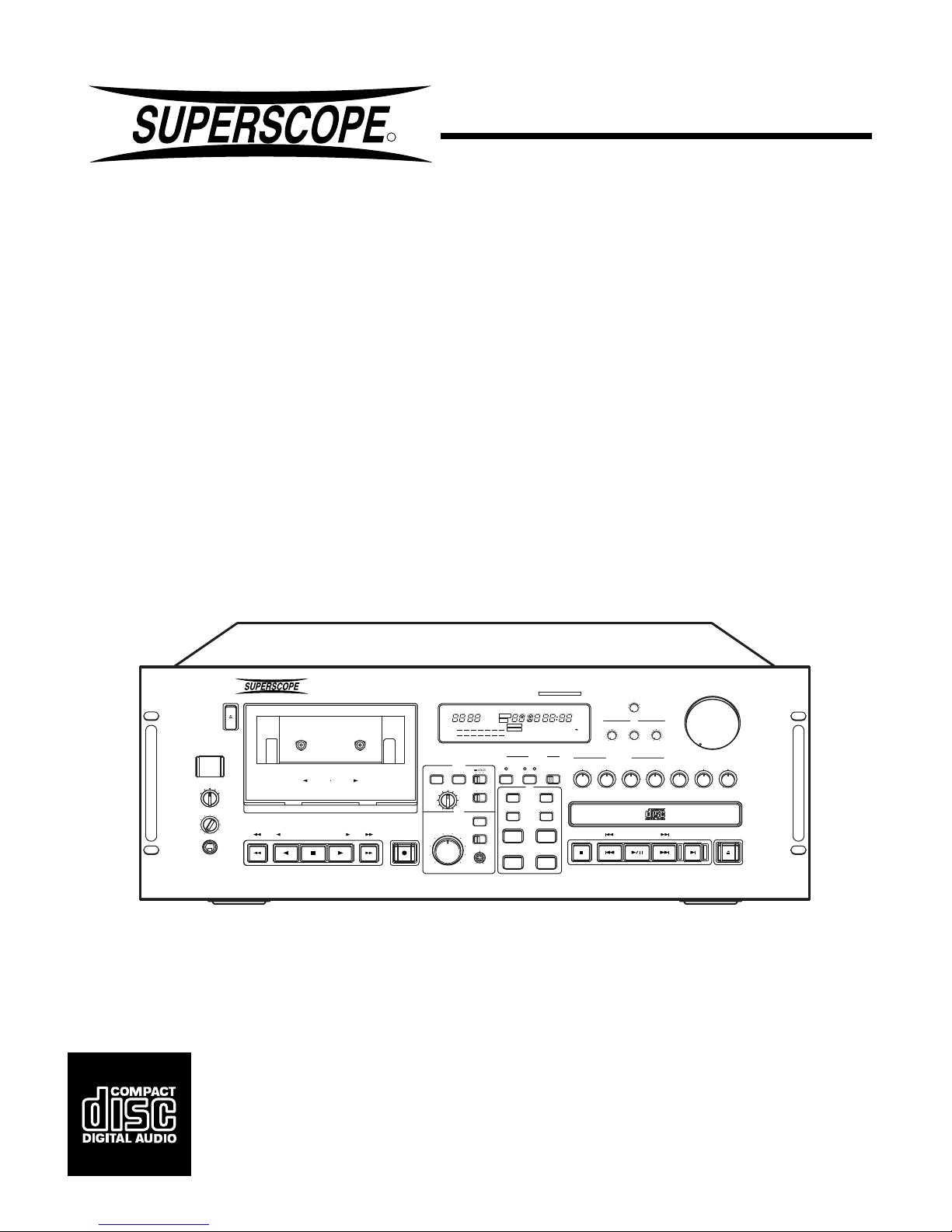
Thank you for selecting the Superscope PAC750/PAC770. Please read
these operating instructions carefully. We recommend that you read the
entire user guide prior to connecting and operating the unit. It is also
recommended that all connections be made prior to operating the unit.
Please refer to this manual to identify controls and connections for
operation of the unit.
PRECAUTIONS
The following precautions should be considered when operating the
equipment.
When setting the equipment ensure that :
– air is allowed to circulate freely around the equipment
– the equipment is on a vibration free surface
– the equipment will not be exposed to interference from an external
source
– the equipment will not be exposed to excessive heat, cold, moisture
or dust
– the equipment will not be exposed to direct sunlight
– the equipment will not be exposed to electrostatic discharges
¡In addition, never place heavy objects on the equipment.
¡If a foreign body or water does enter the equipment, contact your
nearest dealer or service center.
¡Do not pull out the plug by pulling on the mains lead. Hold the plug.
FEATURES
BUILT-IN MIXER
The PAC750/PAC770 incorporate a built-in mixer that includes inputs
and control for the built-in Tape and CD players, the stereo Aux input,
and the 4 mono Mic/Line inputs. The Aux input allows an unbalanced
stereo line level source to be connected. The 4 mono Mic/Line inputs
allow either a microphone (either high or low sensitivity) or line input to
be connected. EQ and pan controls are provided on those inputs to
allow for feedback elimination and mixer customization.
AUTO DUCKING
The PAC750/PAC770 incorporate an Auto Ducking feature that allows
the Mic/Line inputs to work in conjunction with the Tape, CD, and Aux
inputs. With the Auto Ducking feature set to -15dB, everything works as
normal except for when any of the Mic/Line inputs has an active signal.
When this occurs, the Tape, CD, and Aux inputs drop down in level by
-15dB. When Auto Ducking is set to -∞, the Tape, CD, and Aux inputs
are dropped out completely when the Mic/Line inputs are active.
VOICE REDUCTION
The Tape, CD, and Aux inputs to the mixer contain a Voice Reduction
circuit that can effectively reduce the vocal tracks in most music. Please
be aware that results vary according to the music and the way it was
recorded.
AMPLIFIER (PAC770)
The PAC770 contains a powerfull amplifier that allows versatile speaker
connection. The 1/4" connectors are very convenient for portable use
while the binding posts allow connection of single-ended banana plugs
or a secure bare wire connection.
TEMPO CONTROL
The PAC750/PAC770 CD player allows for the adjustment of the playing
speed (Tempo) from -50% to +50%. This feature is similar to Pitch
control except that the Key (musical pitch) of the CD output does not
change when the Tempo is adjusted.
KEY CONTROL
The PAC750/PAC770 CD player allows for the adjustment of the Key
(frequency/musical pitch) from -1 octave to +1 octave during playback.
This feature allows the music to be adjusted in order to match correctly
to an instrument or a voice.
A-B LOOP
The PAC750/PAC770 allows two points within the CD to be selected and
the audio within these points will be repeated until a stop command is
issued.
SINGLE TRACK PLAY
The PAC750/PAC770 can be set for the CD player to play the selected
track and then stop and cue up the next track.
AUTO CUE
This feature allows the CD player to advance to the beginning of the
audio within the track rather than start from the track start flag. This
feature helps to minimize the silence at the beginning of a CD track.
PITCH CONTROL
The PAC750/PAC770 tape player allows for adjustment of the playback
pitch (key + tempo) from -12% to +12%. The feature is particularly useful
to tune a tape to accompanying instruments and choirs.
QUICK OPTICAL AUTOREVERSE
In addition to the normal tension reversing circuitry the PAC750/PAC770
tape transport also employs optically sensing quick autoreverse cir-
cuitry. This circuitry reacts to the clear areas of the tape, usually the
leader tape, and when detected will reverse the direction of the tape
transport. This process minimizes the lose of signal being recorded or
played back. This reverse process applies to all tape playback and
recording modes, including autoreverse and continuous mode.
DOLBY NR SYSTEMS
The Dolby Noise Reduction systems compress and amplifies the input
signal during recording in order to raise the signal-to-noise ratio on the
tape. During playback, these signals are expanded and attenuated by
the same amount in order to regain the original dynamic range of the
music. An additional result of this expansion and attenuation is that the
noise floor of the recording is reduced significantly. Dolby B typically
reduces noise by 10dB and Dolby C typically reduces noise by 20 dB.
DOLBY HX PRO HEADROOM EXTENSION
The Dolby HX PRO system monitors the total amount of effective bias
during recording and instantaneously compensates for any excess bias
by reducing the tape deck’s bias signal level accordingly. The system
operates independently on each channel. HX Pro is unlike a noise
reduction system because it functions only during recording and no
decoding is required. Therefore a tape recorded with the HX Pro system
can be played back on any other cassette deck while retaining the
benefits of HX Pro.
ONE TOUCH DUBBING
The PAC750/PAC770 allows dubbing of the CD to the tape with one
button start control. This feature allows manual or automatic record level
control.
RC5 REMOTE CONTROL COMPATIBILITY
The PAC750/PAC770 comes equipped with an RC5 remote in and out
port. Through the use of various remote control options, major functions
of the unit can be operated via wired or wireless remote control.

ENGLISH
9
REAR PANEL CONNECTIONS
AAUX INPUT JACKS
These jacks should be connected to the LINE OUTPUT of your
source.
BLINE OUTPUT (CD, TAPE, PRE-AMP(MIX)) JACKS
These jacks can be connected to the appropriate LINE INPUT of a
power amp, PA or monitoring system.
CEFFECT INPUT & OUTPUT JACKS
These jacks are used to connect to a graphic equalizer or an effects
processor. When such a device is connected, set the EFFECT
switch to the ON position. When such a device is not connected, set
the EFFECT switch to the OFF position.
¡If the switch is left ON without anything connected, no audio will be
output through the pre-out or the speakers.
DMPX FILTER SWITCH
When recording FM broadcasts, set this switch to the ON position to
eliminate the FM carrier signal.
EREMOTE CONTROL JACKS
These jacks are used with an infrared or wired remote control to
provide remote operation of the PAC750/PAC770.
The signal format of this interface is Philips RC5.
¡These jacks can be serially linked to provide serial remote control
operation of multiple RC5 equipped products as well.
FMONO BRIDGE SWITCH (PAC770)
¡This switch is used to select between mono bridge and stereo
amplified output mode.
When this switch is in the OFF position, the unit functions as a stereo
power amp. When this switch is in the ON position, the unit functions
as a monaural amp. (For details on how to connect the speakers,
refer to page 52.)
¡This switch only effects the binding post speaker outputs and not the
1/4” speaker outputs.
¡Make sure this switch is OFF when the 1/4” speaker outputs are
used.
G, KAMPLIFIED SPEAKER OUTPUTS (PAC770)
These jacks are used to connect to passive (non-powered) speakers.
When using a speaker system in stereo mode with left and right
channels, connect the right channel speaker to the output terminal
Glabeled “R,” and the left channel speaker to the output terminal G
labeled “L”. In stereo mode, use a speaker system with an impedance
of 4 to 16 ohms.
When using a single (mono) speaker system, set the MONO BRIDGE
switch to “ON”. Connect the speaker to the red terminals for both the
“L” and “R” speaker terminals G. Do not use the black terminals. In
mono mode, use a speaker system with an impedance of 8 to 16
ohms.
¡MONO BRIDGE mode is only available on the binding post speaker
outputs and not the 1/4” speaker outputs.
HFUSE Holder
CAUTION : Disconnect AC power before removing.
This receptacle holds a specific fuse that is used to prevent overload
and shorting.
IAC TERMINAL
Connect the AC cord that is provided with the unit to this terminal.
JSPEAKER SELECT SWITCH (PAC770)
This switch is used to select between the two sets of speaker
terminals (Kand G).
¡Speaker terminals Kand Gcannot both be used simultaneously.
¡Speaker terminal Kdoes not permit mono bridge connection.
However, make sure the MONO BRIDGE switch is in the OFF
position.
LEQ & PAN CONTROLS
The recessed EQ controls allow the tone of each MIC/LINE input to
be adjusted to obtain optimum sound quality. Turning each control
to the right boosts the corresponding frequency range and to the left
attenuates it.
LOW : Controls the tone of the lower frequencies. (100Hz)
HIGH : Controls the tone of the higher frequencies. (15kHz)
The recessed PAN control adjusts the MIC/LINE input to the desired
position (L, R or L + R) in the mixing bus.
When the knob is at the center position, the MIC/LINE signal is
centered between the left and right. To position the output on the left
side, turn the knob towards “L”. To position the output on the right
side, turn the knob towards “R”.
MMIC/LINE INPUT JACKS
Each set of these inputs is designed to accept either a microphone
(MIC) or line (LINE) level signal. All of the input jacks are balanced.
For a microphone level signal, set the MIC ⇔LINE switch to the MIC
position. For all MIC inputs, set the SENSITIVITY to either HIGH or
LOW, according to the sensitivity of the microphone. If a microphone
that requires phantom power is used with the XLR input, set the
PHANTOM switch to the “ON” position.
For a line level input, set the MIC ⇔LINE switch to the LINE position.
¡The XLR input and the 1/4” input cannot be used at the same time.
NSYSTEM OUTPUT JACKS (PAC750)
The system output jacks are the final output of the mixer and can be
used when connecting the PAC750 to a power amp, PA, or monitoring
system. The RCA jacks are unbalanced outputs. The XLR jacks are
balanced outputs.

ENGLISH
10
FRONT PANEL FEATURES
qPOWER BUTTON
Push this switch in to turn the unit on and off. When power is turned
off, all past settings are removed from memory and the unit returns
to its default setting upon the next power up.
wCASSETTE TAPE HOLDER
This holds the cassette tape for playback and record functionality.
Tapes that have the record protect tab removed will not enter into the
record mode.
eEJECT BUTTON
Press this button to open the cassette tape holder.
rTAPE DECK AND CD PLAYER CONTROL
TAPE DECK CONTROL BUTTONS
77
77
7STOP BUTTON
Press this button to cancel all current operations of the tape deck.
33
33
3FORWARD PLAY BUTTON
Press this button to engage the tape deck into the forward play
function.
22
22
2REVERSE PLAY BUTTON
Press this button to engage the tape deck into the reverse play
function.
11
11
1REWIND BUTTON
Press this button to engage the tape transport into the fast rewind
mode from the right (take-up) to the left (supply) reels. When this
button is pressed during playback, the tape deck will search for the
next program in the reverse direction.
¡¡
¡¡
¡FAST FORWARD BUTTON
Press this button to engage the tape transport into the fast forward
wind mode from the left (supply) to the right (take-up) reels. When
this button is pressed during playback, the tape deck will search for
the next program in the forward direction.
¶¶
¶¶
¶REC/PAUSE BUTTON
Press this button to engage the tape transport into the record-pause
mode. In this mode the tape deck is ready to begin recording. The
tape record mode can be engaged by pressing the FORWARD
PLAY 3or REVERSE PLAY 2buttons.
CD PLAYER CONTROL BUTTONS
00
00
0OPEN/CLOSE BUTTON
Press this button to open the CD door and eject the disk. Press this
button again to close the CD door and read the disc.
¡The OPEN/CLOSE button is disabled during the play mode.
77
77
7STOP BUTTON
Press this button to stop the CD player while in the play mode. During
the program mode, the STOP button will cancel the current program
when the CD player is in the stop mode.
66
66
6PLAY/PAUSE BUTTON
When this button is pressed during the stop mode, the CD player will
start playback from the beginning of the disc or program, and then
continue to play until the end of the disc or program.
When this button is pressed during the play mode, the CD player will
enter the pause mode.
When this button is pressed during the pause mode, the CD player
will enter the play mode.
44
44
4PREVIOUS/REVERSE SEARCH BUTTON
When this button is pressed during the stop mode, tracks can be
selected for playback by searching in the reverse order, starting
from the last track on the disc.
When this button is pressed during the play mode, the CD player will
skip back to the beginning of the current track. If immediately
pressed again, the CD player will skip back one track for every time
the button is pushed.
During the program mode, this button is used to select the tracks to
be saved in the program.
If this button is pressed and held during playback, the CD player will
enter audible reverse search mode until the button is released.
¢¢
¢¢
¢NEXT/FORWARD SEARCH BUTTON
When this button is pressed during the stop mode, tracks can be
selected for playback by searching in the forward direction, starting
from track number 1.
When this button is pressed during the play mode, the CD player will
skip forward one track for every time the button is pushed.
During the program mode, this button is used to select the tracks to
be saved in the program.
If this button is pressed and held during playback, the CD player will
enter the audible forward search mode until the button is released.
SINGLE PLAY BUTTON
Press this button to toggle the Single Track Play feature on and off.
When on, the TRACK (g) indicator in the display will flash and, during
playback only, the Single Play button will light. When the CD player
is stopped, only the TRACK inicator will flash to indicate that the
Single Track play mode is active. The Single Track button will not
light so it does not look like the CD player is playing while it is
stopped.
Once the Single Track play mode has been activated, it will stay on,
even if discs are changed, until it is turned off or the power has been
switched off.
When Single Track Play is activated, the CD player will do two things
differently than normal: first, each time a track is selected via the 4
and ¢buttons, the track will not start playing but will enter the
Pause mode at the beginning of the audio (cued up). Second, when
a track that is playing comes to an end, the next track will not start
playing but will be cued up to the audio in Pause mode.
¡While the CD player is stopped, Single Track play can be turned on
and off but is only indiated by the flashing TRACK (g) indicator.
Once playback starts, the Single Play button will light.
¡Single Track play can be switched on or off at any time by pressing
the Single Track button.
tTAPE COUNTER BUTTON
MEMO BUTTON
Press this button to store the current tape location into the counter
memory. Once this memory point is set, the tape deck will rewind or
fast forward until it reaches this point in the tape and will stop. To
clear the memory press the MEMO button again.
RESET BUTTON
Press this button to reset the current tape counter reading from its
existing point to “0000”.
yAUTO DUBB BUTTON
Press this button to engage the tape transport into the dubbing
mode from the CD player.
¡See page 15 for more information on the operation of this function.

ENGLISH
11
uTAPE PITCH KNOB
Rotate this knob to adjust the tape deck playback pitch (key +
tempo) from -12% to +12%. While the control is in the center detent
position, the tape deck is at normal (0% variance) pitch.
¡This control has no effect on the tape pitch during the record mode.
iKEY BUTTONS
These buttons can be used to change the key (frequency/musical
pitch) of the sound from the CD by up to ±1 octave.
The “+” key raises the key in 12 1/2 cent increments. Press and hold
the “+” button to quickly increase the key.
The “–” key lowers the key in 12 1/2 cent increments. Press and hold
the “–”button to quickly decrease the key.
Press both “+” and “–” at the same time to quickly return the key back
to 0.00 position (normal key).
¡See page 15 for more information on the operation of this function.
oTIME BUTTON
By pressing the TIME button you can toggle the CD player time
display with the following. Normal (no indication) - Displays the time
elapsed within the current track being played. REM- Displays the
remaining time left of the current track being played. TOTAL REM-
Displays the total time remaining on the current disc being played.
!0 REPEAT BUTTON
This button can be used to set the CD player in all track or single track
repeat play mode. The first press of the REPEAT button places the
CD player in the all track repeat mode and the “REPEAT” indicator
will light in the display. The second press of the REPEAT button
places the CD player in single track repeat mode and the “REPEAT”
and “1” indicator will light in the display. The third press of the
REPEAT button will exit all repeat play modes.
!1 A-B BUTTON
This button allows you to repeat a specific section in the current CD
track that is being played. When this control is pressed the first time,
the A-B indicator flashes and this position on the track is noted as the
start or A point.
When this control is pressed again, the A-B indicator lights
continuously, and this position on the track is noted as the end or B
point. After setting the end point, the CD player returns to the start
point (A), and plays until it reaches the end point (B). The CD player
will repeat this function until the STOP or REPEAT button is pressed.
Subsequent press of this button will change the B point into the A
point and allow a new B point to be set.
¡See page 14 for more information on the operation of this function.
!2 PROGRAM BUTTON
When this button is pressed once, the CD player enters the program
entry mode and the program indicator will begin to flash. Pressing
the PROGRAM button again will return the CD player to the normal
play mode.
¡See page 14 for more information on the operation of this function.
!3 REVERSE MODE SWITCH
This switch sets the automatic tape direction of the tape transport
during playback, normal recording, or dubbing.
:One-way mode.
In this position the tape will play or record one side of the tape
and stop.
:Two-way mode.
In this position the tape will play or record both sides of the tape
and stop.
:Continuous mode
In this position the tape will play the tape in a continuous loop
until the stop command is given. In the record mode the tape will
record both sides of the tape and stop.
!4 DOLBY NOISE REDUCTION SWITCH
This switch allows for the encoding or decoding of Dolby B or C
Noise Reduction. When recording with Dolby Noise Reduction,
select the type (B or C) of noise reduction desired and place the
switch in the appropriate position. When playing a tape with Dolby
Noise Reduction encoded onto it, place this switch in the same
position (B or C) as it was recorded in.
!5 ALC (AUTOMATIC RECORD LEVEL CONTROL) SWITCH
This switch performs automatic control of the input level during
recording. When this switch is set to the OFF position, the recording
level is controlled by the record level knob. When this switch is set
to the ON position, the record level is set automatically and the
record level knob is disabled.
!6 RECORD LEVEL KNOB
This knob controls the record level up or down during manual
recording.
!7 RECORD BALANCE CONTROL
This recessed control allows for the adjustment of the record level
between the left and right channels. By using a phillips type
screwdriver, you can adjust this balance control between left (counter-
clockwise) and right (clockwise).
!8 HP (HEADPHONE) SELECT SWITCH
This switch is used to select which source is monitored through the
headphone jack.
!9 HEADPHONE JACK
This output jack is used to connect to a set of headphones.
¡This jack requires a 1/4” type connector.
@0 CD TRAY
The CD tray is used to hold a CD for playback.

ENGLISH
12
@2 HP (HEADPHONE) LEVEL KNOB
This knob is used to control the volume level of the headphone
output.
@3 TEMPO BUTTONS
These buttons are used to change the tempo (speed) of the sound
from the CD by up tp ±50%.
The UP button increases the speed in steps of 1%.
The DOWN button decreases the speed in steps of 1%.
If both the UP and DOWN buttons are pressed at the same time, the
TEMPO will return to the 0% position (normal speed).
¡See page 14 for more information on the operation of this function.
@4 TAPE/CD/AUX GAIN KNOBS
These knobs are used to determine the amount of signal from the
TAPE, CD and AUX sources that is input to the mixer.
@5 MIC/LINE (1 to 4) GAIN KNOBS
These knobs are used to determine the amount of signal from the 4
MIC/LINE sources that is input to the mixer.
@6 MASTER VOLUME KNOB
This large knob is used to control the final output level of the mixer
through the PRE-OUT (PAC770), SYSTEM OUT (PAC750), and
AMPLIFIED OUT (PAC770).
@7 EQ (LOW, MID, HIGH) CONTROLS
Turn these knobs to adjust the tone of the mixed output. Each a knob
controls the level of the corresponding frequency range. Turning
each control toward “+” boosts the corresponding frequency range
and toward “-” attenuates it.
LOW : Controls the tone of the lower frequencies. (100 Hz)
MID : Controls the tone of the midrange frequencies. (1 kHz)
HIGH : Controls the tone of the upper frequencies. (15 kHz)
@8 BALANCE CONTROL
This knob can be used to correct a left/right imbalance, to isolate the
left or right channel during mono playback, or to compensate for
different left/right acoustics in a room or in a particular situation.
¡Please note that when this knob is turned fully clockwise or counter-
clockwise all sound is muted on the opposite channel.
@9 AUTO GAIN CONTROL SWITCH (MIC/LINE)
This switch is used to select if the mixer level of the MIC/LINE inputs
are controlled automatically or manually.
OFF : The MIC/LINE gain knobs are used to adjust the mixer level.
ON : The MIC/LINE mixer levels are controlled automatically and
the gain knobs are disabled.
#0 AUTO DUCKING SWITCH
This switch is used to automatically adjust the CD, TAPE and AUX
mixer levels in response to the MIC/LINE inputs.
The reduction level can be selected by pressing the button. Pressing
the button cycles through the following settings: -15 →-∞→OFF.
-15 : The CD, Tape and AUX levels are reduced by 15dB when any
MIC/LINE input is active.
-∞: The CD, Tape and AUX levels are eliminated when any MIC/
LINE input is active.
If the MIC/LINE input level goes down, the CD, TAPE and AUX output
levels return to their original levels after 1 to 3 seconds.
#1 VOICE REDUCTION SWITCH
This switch automatically reduces the vocals on the TAPE, CD and
AUX sources.
¡The performance of this function is determined by the way the
source material was recorded. Recordings with the vocals centered
equally between the lest and right channels works best.
@1 DISPLAY INDICATORS
aCOUNTER display indicates the amount of tape that has travelled
across the head.
bLEVEL indicators display the record or playback signal levels of
the tape deck.
cDOLBY NR B C indicators display the type of Dolby noise
reduction that has been selected.
dMEMO indicator is displayed when the tape deck memory
function is turned on.
eHX PRO indicator is displayed showing HX PRO is activated.
fDUBB indicator is displayed when dubbing from the CD player
to the tape deck.
gTRACK number indicator displays the total amount of CD tracks
in the disc or program during stop and the current track playing
in the play mode.
TRACK indicator will flash when the CD player is in the Single
Track Play mode.
hTIME indicator displays the playing time of the CD in 4 digits
representing minutes and seconds. This display typically
represents elapsed time of the track being played. When the
REM indicator is displayed, the time shown represents the
remaining time of the track being played. When the TOTAL REM
indicator is displayed, this represents the total remaining time of
the CD or of the program currently being played. In the stop
mode the total playing time of the CD is displayed.
iTRACK number indicator (1 through 20) displays the track
numbers on the CD. When in the program mode, the tracks
programmed are displayed. Upon completion of playing a track,
the number will disappear. When playing a CD with more than
20 tracks on it, the “⇒” indicator is displayed.
jPROGRAM indicator is displayed to indicate that the CD player
is in the program mode. The indicator flashes during the program
entry mode. This indicator can be turned on and off by pressing
the program button.
kREPEAT indicator is displayed when the CD player is in the all
track repeat mode. REPEAT 1 is displayed when the CD player
is in the single track repeat mode.
lA-B indicator is displayed when the CD player is in the A-B
repeat mode. When the A-B indicator is flashing, this indicates
standby for the setting of point B.
mREC indicator is displayed when the tape deck is in the record
mode. When the REC indicator is flashing, this indicates the tape
deck is in the record pause mode.
nTAPE DECK PLAY indicators (located inside the tape PLAY
buttons) displays the direction and mode of the tape transport.
When the indicator is flashing, this indicates the transport is in
the pause mode in the indicated direction. When the indicator is
constantly on, this indicates that the transport is in the play or
record mode in the indicated direction. This indicator will not
light if there is not a tape in the transport.
oCD PLAYER PLAY indicator (located inside of the CD PLAY/
PAUSE button) displays a constant indicator when the CD
player is in the play mode and a flashing indicator when in the
pause mode.
pCD PLAYER SINGLE PLAY indicator (located inside the SINGLE
PLAY button) displays a constant indicator when the CD player
is in the single track play mode and a flashing indicator when in
the single track pause mode.
When the CD player is stopped and the Single Track play feature
has been turned on, the indicator will not light but the Single
Track play mode is still active and is indicated by the flahsing
TRACK (g) indicator.
i
REM
TOTAL
TRACK
REPEAT1
PROGRAM
A-B
MEMO
HX
DUBB
NR
DOLBY
PRO
BC
19181716151413121110
987654321
+3
0
-3-6
-10-15-20
R
L
20
ahgdef
bc jkl

ENGLISH
13
OPERATION
The following operating procedures are based on the assumption that
the power is on and that all necessary input and output connections have
already been made. Please refer to the section in this manual marked
“Rear Panel Connections”.
MIXER OPERATION
The PAC750/770 includes a versatile built-in Mixer that allows the output
to be coordinated with the Tape deck, CD player, AUX input, and the four
Mic/Line inputs. Each input to the Mixer has a gain control knob on the
front panel that controls the amount of signal that is added to the mix.
The final output of the Mixer is controlled by the MASTER VOLUME knob
@6, the EQ controls @7, and the BALANCE knob @8.
The final output of the Mixer is then sent to the PRE-OUT (SYSTEM OUT
on the PAC750) as a line level signal. On the PAC770, the signal is also
sent to the internal amplifier and then output on the SPEAKER terminals,
which can be attached directly to an appropriate speaker system.
The Mixer In Relation To The Tape Deck
The recording circuitry of the Tape Deck is directly patched into the
mixer, meaning that the Tape Deck will record whatever the Mixer
outputs. Therefore, the final level recorded onto the tape will be determined
by the setting of the Mixer gain controls and the Tape Deck record level
control.
CASSETTE DECK OPERATION
Cassette Tape Playback
1. Open the cassette holder by pressing the eject button. Load a
cassette tape into the cassette holder and close. The 3indicator on
the play forward button will begin to flash.
2. Set the DOLBY NOISE REDUCTION switch to the same position as
the tape was originally recorded in (i.e. tapes recorded with Dolby B
noise reduction need to have this switch in the Dolby B position, tapes
recorded with Dolby C noise reduction need to have this switch in the
Dolby C position, and tapes recorded without Dolby Noise Reduction
need to have this control set to the Off position).
3. Set the reverse mode switch to the desired position.
4. Press the 3PLAY button to begin playback in the forward direction.
Press the 2PLAY button to begin playback in the reverse direction.
When the tape enters into the playback mode the indicator on the play
control button will change from the flashing mode to a constant on
mode.
5. Adjust the gain into the mixer using the TAPE knob @4.
6. Adjust the volume with the VOLUME knob @6.
7. Pressing the STOP button rwill stop the tape.
Searching For Tracks
While a tape is playing back, pressing the ¡(Fast Forward) or 1
(Rewind) button will cause the tape deck to forward search for the next
track or reverse search to the beggining of the current track, depending
on the direction of playback.
When the search is concluded, the tape deck will stop.
Notes
¡For normal Fast Forward and Rewind, the STOP button must first be
pressed.
Rewind & Fast Forward
When the tape deck is stopped, and regardless of the current direction,
pressing the ¡(Fast Forward) button will place the tape transport in the
high speed fast forward mode and the tape will advance quickly from left
to right. Pressing the 1(Rewind) button will place the tape transport
in the high speed rewind mode and the tape will retract quickly from right
to left.
In either the fast forward or the rewind mode, the tape transport will
continue to fast forward or rewind until the stop control button is pressed
or the end of the tape or a saved memo point is reached.
Cassette Tape Record
1. Open the cassette holder by pressing the eject button. Load a
recordable cassette tape into the cassette holder and close. The 3
indicator on the play button will begin to flash. (If you wish to change
the tape direction, press the 2PLAY button and then press the STOP
button).
2. Set the DOLBY NOISE REDUCTION switch to the desired position to
record the tapes with noise reduction (i.e. tapes to be recorded with
Dolby B noise reduction need to have this switch in the Dolby B
position, tapes to be recorded with Dolby C noise reduction need
to have this switch in the Dolby C position, and tapes to be recorded
without Dolby Noise Reduction need to have this switch set to the OFF
position).
3. Set the reverse mode switch to the desired position.
4. Set the AUTO LEVEL switch to the desired position.
5. Press the REC button. The REC indicator will begin to flash indicating
the tape transport is in the record-pause mode.
6. If the AUTO LEVEL switch is in the OFF position, use the manual
record level control to adjust the input signal to the desired recording
level.
7. Press the 3PLAY control button to begin recording in the forward
direction.
8. To pause recording, press the REC button. Press the PLAY button to
resume recording.
9. Pressing the STOP button will stop recording.
Erasure Of Tape
When a program source is recorded onto a tape, the previously re-
corded sound is erased automatically, and replaced with the new
recording. If you wish to erase a tape without recording, set the
RECORD LEVEL control to the minimum (0) position and record.
Set the AUTO LEVEL off.
To Protect Valuable Recordings
In the record mode, information previously recorded on the tape will
automatically be erased. To prevent this from happening, use a small
screwdriver to break out one or both safety tabs (See Figure 2 on pg. 17).
It is possible to restore the recording capability of either side of the
cassette by covering the opening with clear adhesive tape (See Figure
4 on pg. 17).
Auto Tape Selector
This unit is equipped with an auto tape selector which automatically sets
the bias and equalizer level using the detection holes provided in the
cassette shell. The bias and equalizer levels are automatically set
according to the type of cassette as follows. (See Figure 3 on pg. 17)
¡Normal tapes EQ = 120µS, Bias = Low
¡High tapes EQ = 70µS, Bias = High
¡Metal tapes EQ = 70µS, Bias = Metal

ENGLISH
14
CD PLAYER OPERATION
CD Playback
1. Open the CD tray by pressing the OPEN/CLOSE button. Place a CD
onto the tray and close the tray by pressing the OPEN/CLOSE button.
The display will show the general data of the current CD after it has
been read.
2. To begin playback of the CD, press the PLAY/PAUSE button. The 3
indicator in the PLAY/PAUSE button will illuminate, the display will
show the data for the first track, and the track will begin to play.
3. Adjust the gain into the mixer using the CD knob @4.
4. Adjust the volume with the VOLUME knob @6.
5. To pause the CD during playback, press the PLAY/PAUSE button.
The CD will remain in the current position and the 3indicator in the
PLAY/PAUSE button will begin to flash. Pressing the PLAY/PAUSE
button will resume playback from the point that the CD player was
paused.
6. Playback will continue until the end of disc is reached or the STOP
button is pressed.
Selecting The Playback Track
By pressing the ¢NEXT or 4PREVIOUS buttons you can select
the track to be played. Each press of the ¢button will advance the
player to the beginning of the next track.
Each press of the 4button will cause the CD player to skip to the
beginning of the current track. If immediately pressed again, the CD
player will skip back one track for every time the button is pushed.
A-B Repeat
1. Start playback.
2. Press the A-B button at the beginning of the part you want to repeat.
“REPEAT” lights and “A-B” blinks in the display.
3. Press the A-B button again at the end of the part you want to repeat
to start the A-B repeat.
“REPEAT A-B” lights in the display.
4. Press the A-B button again to change the end point (point B) to the
new start point (new point A).
5. After the new start point is passed, press the A-B button again to set
the new end point (new point B) and re-start A-B repeat.
6. To continue to re-mark the A-B repeat points, repeat steps 4 and 5.
7. Press the REPEAT button to return to the normal play mode.
Notes
¡A-B repeat across more than one track is not possible. (If the next track
starts after having set point A in a track, A-B repeat is canceled
automatically.)
Pressing the “+” key Pressing the “–” key
TEMPO 0% TEMPO 0%
+1% -1%
+2% -2%
+3% -3%
TEMPO +50% TEMPO -50%
Pressing A-B during A-B
repeat changes point B to
point A. (step 4)
A
AB
Point B cannot be
set in this section.
Programming Playback Tracks
(PROGRAM PLAY MODE)
This procedure allows a program of selected tracks for playback in any
order.
1. By pressing the PROGRAM button once you will place the CD player
into the programming mode. Once the PROGRAM button is pressed,
the PROGRAM indicator in the CD display will begin to flash. This
indicates the CD player is in the program entry mode.
2. By pressing the ¢NEXT or the 4PREVIOUS button, tracks to
be programmed are selected. Each press of the ¢button will
advance the CD player to the next track. Each press of the 4button
will cause the CD player to skip to the previous track. When the
desired track number has been selected, leave the CD player
untouched for approximately 1.5 seconds and the selected track will
be stored in the program. Continue this procedure until all desired
tracks (30 tracks maximum) have been programmed.
3. By pressing the PLAY/PAUSE button, the CD player will exit the
program entry mode and enter the program play mode. The
PROGRAM indicator in the CD display will light constantly and the
CD player will begin to play in the order selected during the program
entry mode.
4. By pressing the STOP button, the CD player will stop playing but will
remain in the program play mode. The program will remain in
memory.
5. When the STOP button is pressed while the CD player is in the stop
mode, the memorized program will be cleared.
Tempo Control
The PAC750/PAC770 is equipped with the ability to change the CD
playback speed by up to ±50% without changing the key (musical pitch)
of the sound from the CD.
The “+” button increases the speed in steps of 1%.
The “–” button decreases the speed in steps of 1%.
Holding down either the “+” or “–” buttons for more than 1 second causes
the speed to change rapidly.
Pressing both the “+” and “–” buttons at the same time will return the
TEMPO to the 0% position (normal speed).
Display
¡If the “+” or “–” buttons are pressed while the time display is shown,
the current position of the TEMPO control is displayed the first. Once
one of the “+” or “–” are pressed a second time, the position then
changes.
¡If the KEY has been changed, TEMPO control is not available.
Restore KEY control to the 0.00 position in order to use TEMPO
control.

ENGLISH
15
CD TO TAPE DUBBING
The CD player can dubb directly to the tape deck either manually or
automatically. Manual dubbing allows the recording level to be set by the
RECORD LEVEL knob and then recording is started manually. Auto-
matic dubbing adjusts the recording level automatically based on the
peak levels of the CD and then starts recording automatically.
Manual Record Level Dubbing
1. By pressing the OPEN/CLOSE button and the tape EJECT button,
load the source CD onto the CD tray and a recordable tape into the
tape holder. Close both the CD tray and the tape holder. The display
will show the general CD data and the tape play indicator located
inside the tape PLAY button will begin to flash.
2. Prepare the tape for dubbing by rewinding it to the beginning of the
first side that the tape is to be recorded onto.
3. Set the AUTO LEVEL switch to the OFF position.
4. Press the AUTO DUBB button once. The REC indicator will begin to
flash, the DUBB indicator will light, and the CD player will enter the
play mode. At this point you can adjust the record level to achieve the
desired recording level.
5. After adjusting the record level, press the AUTO DUBB button again.
The CD player will return to the stop mode, and the tape transport will
enter into the record mode. After approximately 5 seconds, the CD
player will enter the playback mode and begin to play the first track,
dubbing it onto the tape.
6. When either the CD transport or the tape transport have reached the
end and stopped, the other transport will also stop.
7. To end the dubbing during a session, press the STOP on the tape
deck or the STOP button on the CD player.
Automatic Record Level Dubbing
1. By pressing the OPEN/CLOSE button and the tape EJECT button,
load the source CD onto the CD tray and a recordable tape into the
tape holder. Close both the CD tray and the tape holder. The display
will show the general CD data and the tape play indicator located
inside the tape PLAY button will begin to flash.
2. Prepare the tape for dubbing by rewinding it to the beginning of the
first side that the tape is to be recorded onto.
3. Set the AUTO LEVEL switch to the ON position.
4. Press the AUTO DUBB button once. The REC indicator will begin to
flash, the DUBB indicator will light and the CD player will enter play
mode. The CD player will automatically begin to search the CD for the
peak level. This procedure could take as long as 5 minutes to
complete. Once the peak level has been determined, the record level
for dubbing will be set automatically.
5. After the record level has been set, the tape transport will enter into
the record mode. After approximately 5 seconds, the CD player will
enter the playback mode and begin to play the first track, dubbing it
onto the tape.
6. When either the CD transport or the tape transport have reached the
end and stopped, the other transport will also stop.
7. To end the dubbing during a session, press the STOP on the tape
deck or the STOP button on the CD player.
¡When dubbing is started with a program of CD tracks, the tracks are
dubbed in the order of the program.
¡During dubbing, a blank space of approximately 4 seconds is
automatically inserted between CD tracks. This may hinder some
dubbing such as live recordings on CD. If this is a problem, dubb
from the CD to the tape manually using the mixer.
¡When recording with the reverse mode switch set to the two way or
the continuous mode, there may be an interruption in recording of
approximately 1 second during the optical reversing of the tape
transport.
Key Control
The PAC750/PAC770 is equipped with the ability to change the key (or
musical pitch) of the sound of the CD by up to ±1 octave.
The key control system works on the following musical principles:
100 cents=1 half step
12 half steps=1 octave
The “+” button raises the key in steps of 12.5 cents and is displayed as
a percent of the next half step up, rounded to the nearest tenth. For
example, to raise the key of the CD by 2 1/2 half steps, the display should
show 2.50.
The “–” button lowers the key in steps of 12.5 cents and is displayed as
a percent of the next half step down, rounded to the nearest tenth. For
example, to lower the key of the CD by 3 1/4 half steps, the display should
show -3.25.
Holding down either the “+” or “–” buttons for more than 1 second causes
the key to change rapidly as long as the button is held down.
Pressing both the “+” and “–” buttons at the same time will return the KEY
to the 0.00 position (normal key).
Display
¡If the “+” or “–” buttons are pressed while the time display is shown,
the current position of the KEY control is displayed first. Once one of
the “+” or “–” keys are pressed a second time, the position then
changes.
¡If the TEMPO has been changed, KEY control is not available.
Restore TEMPO control to the 0% position in order to use KEY
control.
CD-RW/CD-R Playback
The PAC750/PAC770 can play back CD-RW (ReWritable) discs as well
as ordinary music CD and CD-R (Recordable) discs.
* The CD-R and CD-RW discs should contain properly-recorded TOC
information so that they can be played back. With the CD recorder
system, writing the TOC information in a disc is referred to as finalizing
the disc. A disc cannot be recognized as a CD disc and played back
unless it has been finalized properly. For details, please read the
instruction manual provided with a CD recorder.
* TOC stands for Table Of Contents and contains information such as
the total number of tracks and total playing time of the disc.
* The PAC750/PAC770 can play only the discs recorded in the CD-DA
format designed for music reproduction. Do not attempt to play a disc
containing other data, such as a CD-ROM for PCs, on this unit.
* As the playback of a CD-RW disc necessitates partial change of the
player setup, it may take longer to read the TOC information compared
to a music CD or CD-R disc.
* Because CD-RW discs have lower reflectivity than CDs and CD-R
discs, dirt on the surface of a CD-RW disc can generate noise, make
the CD-RW disc unplayable, or cause misoperation. If any of these
symptons occur, wipe the surface of the CD-RW disc as indicated on
page 17.
Pressing the “+” key Pressing the “–” key
KEY 0.00 KEY 0.00
+0.13 -0.13
+0.25 -0.25
+0.38 -0.38
+0.50 -0.50
+0.63 -0.63
+0.75 -0.75
+0.88 -0.88
+1.00 -1.00
+1.13 -1.13
KEY +12.00 KEY -12.00

ENGLISH
16
TROUBLESHOOTING
Should faults occur, it is, in many cases, not necessary to consult your
dealer or technical service department. On the basis of the following
checks you will be able to rectify a number of conditions yourself without
difficulty.
If the condition cannot be remedied after the following checks, please
consult your dealer or the Superscope technical service department at
(630) 820-4800.
POWER AMP (PAC770)
Both speakers output monaural sound.
1. Check that the MONO BRIDGE switch is set to OFF.
Sound is output only from one of the speakers.
1. Check the setting of the BALANCE control.
2. Turn the power off and change the connections of the left and right
speakers. If sound is still not output from the same speaker, check its
connection cord or the speaker itself.
Sound is not produced at all.
1. Check that the speaker cords are connected properly.
2. Check that the VOLUME control is not set at the minimum level.
3. Check that the EFFECT ON/OFF switch is OFF, if nothing is con-
nected with the EFFECT jacks.
Sound consistently cuts off.
1. Check the temperature of the unit by placing your hand on the top or
bottom. If the temperature is extremely hot, the amplifier is cutting off
to portect itself. The output level must be decressed in order to
maintain a consistent output.
MIXER
MIC/LINE sound is not produced at all
1. Check that the MIC/LINE gain is not too low.
2. Check that the SENSITIVITY switch is set correctly based on the type
of input.
MIC/LINE sound is distorted
1. Check that the MIC/LINE sensitivity is set correctly.
2. Check that the MIC phantom power is turned on or off.
Hum interferes with the sound.
1. Check that cords are connected properly.
2. Check that there is not any source of magnetism (TV, motor, trans-
former, etc.) placed near the unit.
TAPE DECK
The tape does not travel.
1. Check that the power cord is plugged in properly.
2. Check that the POWER switch is set to ON.
3. Check that the tape is rewound.
The tape travels, but no sound is output.
1. Check that the cassette tape is recorded.
2. Check that the speakers are connected and functioning properly.
3. Check that the TAPE gain and volume control is not set at the minimum
level.
Tape will not record.
1. Check that the protection tabs of cassette tape are not broken.
Sound is distorted.
1. Check that the recording level is not too high.
2. Check that the head is not dirty.
Sound is unstable.
1. Check that the head is not dirty.
2. Check that the pinch wheels and capstans are not dirty.
3. Check that the tape is wound tightly.
Noise is noticeable.
1. Check that the head is not dirty.
2. Check that the head is not magnetized.
3. Check that the DOLBY NR switch is set properly according to the
tape.
CD PLAYER
The disc fails to play.
1. Check that the power cord is plugged in properly.
2. Check that the POWER switch is set to ON.
3. Check that the disc is placed in the correct position on disc tray.
4. Check that the disc is placed properly with the label side facing up.
5. Check that the disc is not dirty, scratched, or warped.
The disc is playing but no sound is heard.
1. Check that the speakers are connected and functioning properly.
2. Check that the CD gain and volume control is not set at the minimum
level.
The disc stops in mid-operation.
1. Check that the disc is not dirty, scratched, or warped.
The sound drops out or noise is heard.
1. Check that the disc is not dirty, scratched, or warped.
REPAIRS
Only the most competent and qualified technicians should be allowed
to service your unit. Superscope and its factory trained warranty station
personnel have the knowledge and special equipment needed for repair
and calibration of this precision instrument.
In the event of difficulty, call the telephone number listed in this owners
manual to obtain service. Please include the model and serial number
of your unit together with a copy of your purchase receipt and a full
description of what you feel is abnormal in its behavior.
CLEANING OF EXTERIOR SURFACES
With proper care and cleaning, the exterior finish of your equipment will
last indefinitely. Never use scouring pads, steel wool, scouring powders
or harsh chemical agents (e.g. lye solution), alcohol, thinners, benzine,
insecticide or other volatile substances, as these will mar the finish of the
cabinet. Likewise, never use cloths containing chemical substances. If
the equipment becomes dirty, wipe the external surfaces with a soft, lint-
free cloth.
If the cabinet becomes heavily soiled:
– dilute some liquid soap in water
– dip a soft, lint-free cloth in the solution and wring the cloth out until it
is damp
– wipe the equipment with the damp cloth
– dry the equipment by wiping it with a dry cloth

ENGLISH
17
COMPACT DISC CARE
Handle discs carefully so as not to damage or scratch the front side.
To protect the disc, avoid placing it in the following locations:
– In direct sunlight or near a source of heat like a heater.
– In a place which is damp or dirty.
– In a place which could be exposed to rain, such as near a window.
Always keep the disc surface clean.
Up to six billion data units are recorded on the front side of the disc.
When cleaning the disc surface, always be sure to use a special
compact disc cleaner and wipe as shown below.
¡Do not use cleaner for analog records, as this will adversely affect the
disc surface.
Store discs properly by placing them in their disc cases.
¡Do not attach a piece of paper or sticker on the label side of disc.
When a disc has a piece of plastic tape or a rental CD label with paste
protruding from the edge or when a disc has a trace of such a sticky
object, do not attempt to play the disc. If such a disc is played on the
CD player, impossibility of taking out the disc or other malfunction may
result.
CASSETTE TAPE CARE
HEAD CLEANING
If the heads are not cleaned for a long period, dirt or dust may be
deposited on the heads and capstans, causing degraded high-fre-
quency characteristics, volume drop, or degraded recording and era-
sure performances.
To prevent this, clean the heads, etc., periodically as follows.
1. Turn the power off.
2. As shown in Figure 1, clean the parts which come in contact with tape,
including the heads, capstans, tape guides, pinch wheels, etc., with
a cotton swab soaked in head cleaning solution or denatured alcohol.
HEAD DEMAGNETIZATION
When a magnetized metallic objects (such as a screwdriver tip, etc.)
comes in contact with a head or capstan, or when the deck has been
used for a long period of time, the head may be magnetized and noise
may be generated. If the head is extremely magnetized, the high
frequencies in recorded tapes could even be erased due to it. To
prevent this, demagnetize the heads and capstans periodically (every
20 hours of use) using a commercially-available head demagnetizer.
(For the operation, please refer to the instruction manual supplied with
your head demagnetizer.)
Caution:
Be sure to turn the power of the cassette deck off before using a
head demagnetizer.
heads
HIGH/Position tape
detection hole
Wipe in a radial direction. Do not wipe in circumferential direction.
capstans
pinch wheels
Figure 1
Figure 2
Metal tape
detection hole
Figure 3
Figure 4

ENGLISH
7
TABLE OF CONTENTS
FRONT AND REAR PANEL DRAWINGS ....................................................................... 5
SPECIFICATIONS ........................................................................................................... 6
INTRODUCTION ............................................................................................................. 8
PRECAUTIONS............................................................................................................... 8
FEATURES...................................................................................................................... 8
REAR PANEL CONNECTIONS ...................................................................................... 9
FRONT PANEL FEATURES ......................................................................................... 10
OPERATION.................................................................................................................. 13
MIXER OPERATION ..................................................................................................... 13
The Mixer In Relation To The Tape Deck ............................................................. 13
CASSETTE DECK OPERATION................................................................................... 13
Cassette Tape Playback ....................................................................................... 13
Searching For Tracks ............................................................................................ 13
Rewind & Fast Forward......................................................................................... 13
Cassette Tape Record .......................................................................................... 13
Erasure Of Tape.................................................................................................... 13
To Protect Valuable Recordings ........................................................................... 13
Auto Tape Selector ............................................................................................... 13
CD PLAYER OPERATION ............................................................................................ 14
CD Playback ......................................................................................................... 14
Selecting The Playback Track............................................................................... 14
A-B Repeat............................................................................................................ 14
Programming Playback Tracks ............................................................................. 14
Tempo Control ...................................................................................................... 14
Key Control ........................................................................................................... 15
CD-RW/CD-R Playback ........................................................................................ 15
CD TO TAPE DUBBING ................................................................................................ 15
Manual Record Level Dubbing .............................................................................. 15
Automatic Record Level Dubbing.......................................................................... 15
TROUBLESHOOTING................................................................................................... 16
REPAIRS ....................................................................................................................... 16
CLEANING OF EXTERIOR SURFACES ...................................................................... 16
COMPACT DISC CARE ................................................................................................ 17
CASSETTE TAPE CARE .............................................................................................. 17
BASIC HOOKUP ........................................................................................................... 51
PAC750 ................................................................................................................. 51
PAC770 ................................................................................................................. 52

5
S
U
F
E
PUSHPUSH
NEUTRIK NEUTRIK NEUTRIK
PUSH
NEUTRIK
PUSH
ONOFF
FILTER
MPX
ONOFF
SENSITIVITIYSENSITIVITIY SENSITIVITIYSENSITIVITIY
48V 48V48V48V
OFF ON
PHANTOM PHANTOM
ONOFF
PHANTOM
OFF ON
L
R
R
L
ONOFF
AUX
IN
OUT
REMOTE
INPUT 2 INPUT 1INPUT 3
R
L
OUT
PHANTOM
EFFECT
RLR
LINE
HIGH
LOW
MIC
LINE
MIC
LINE
MIC
LOW
HIGH
LINE
LOW
MIC
LOW
HIGHHIGH
MIC/LINE
INPUT 4
EQ EQ
IN IN
HIGH
R
EQ
PAN
LOW
LLRL
EQ
PAN PANPAN
R
L
OUT
CD
TAPE
OUT
NEUTRIK
OUT
BALANCED
R
L
OUT
UNBALANCED
L
SYSTEM
R
-
+
1
GND
2
3
-
+
2
GND
1
3
ABCDE H
IML
COMMON
HOT COLD
HIGH
LOW
HIGH
LOW
HIGH
LOW
NEUTRIK
N
PUSHPUSHPUSHPUSH
NEUTRIK NEUTRIK NEUTRIKNEUTRIK
ONOFF
FILTER
MPX
BRIDGE
MONO
ONOFF
SENSITIVITIYSENSITIVITIY SENSITIVITIYSENSITIVITIY
48V 48V48V48V
-
+
(8ΩMIN)
(4ΩMIN)
TO SPEAKER
R AND L
CONNECT
MONO BRIDGE ON:
SPEAKER
OFF ON
PHANTOM
OFF
PHANTOM
ON
ON
OFF
PHANTOM
OFF ON
R
LL
R
R
L
ONOFF
LR
SPEAKER
L
R
(4ΩMIN)
++
SELECT
SPEAKER
AUX
IN
OUT
REMOTE
OUT
INPUT 2 INPUT 1INPUT 3
R
L
OUT
PHANTOM
EFFECT
CD
TAPE
PRE-AMP
RLR
LINE
HIGH
LOW
MIC
LINE
MIC
LINE
MIC
LOW
HIGH
LINE
LOW
MIC
LOW
HIGHHIGH
MIC/LINE
INPUT 4
EQ EQ
OUT OUT
IN IN
R
EQ
PAN
LLRL
EQ
PAN PANPAN
-
+
1
GND
2
3
COMMON
HOT COLD
HIGH
LOW
HIGH
LOW
HIGH
LOW
HIGH
LOW
AB CDEF G
KJIML
S
U
F
E
H
PAC750 REAR PANEL
PAC770 REAR PANEL
PAC750/PAC770 FRONT PANEL
LEVEL
10
9
8
7
6
5
4
3
2
1
0
HP LEVEL
HEADPHONE
HP SELECT
DUCKING
REDUCTION
TEMPO
KEY
UP
10
9
8
7
6
5
4
3
2
1
0
EJECT
REC
AUTO DUBB
DOWN
GAIN
STOP
SINGLE
PITCH
OPEN/CLOSE
-
∞
-15
CD+TAPE+AUX
DOLBY B-C NR HX PRO
ON
AUTO LEVEL
OFF
PLAY PLAY
REC
BALANCE
PLAY/PAUSE
TAPE
CD
4
MIC/LINE
321
AUX
VOLUME
EQ
BALANCE
PLAY
HIGH
LOW
MID
STOP
RESET
A-B
OFF
TIME
L
DOLBY NR
ON
AUTO
CD
TAPE
VOICE
MIC/LINE
REPEAT
R
AUTO
OFF B C
PAC770
PROGRAM
POWER
MEMO
STEREO
PRESET
REM
TOTAL
TRACK
REPEAT1
PROGRAM
AUTO
kHz
MEMO
A-B
MEMO
HX
DUBB
NR
DOLBY
MHz
PRO
BC
H-SP
19181716151413121110
987654321
+3
0
-3-6
-10-15-20
R
L
20
2
SYSTEM
AUXTAPE
CD
MIC/LINE
!8
y!5
@2!9
qut
!
3
@
7
@
6
@
5
@
8
!
4
#
1
#
0
@
9
@
1
ew
i@3!1o!0 @0 @4
!2
nrmopr!6 !7
AUTOMATIC TAPE SELECT SYSTEM
QUICK REVERSE

6
SPECIFICATIONS
MIXER
Input sensitivity
MIC HIGH ................................................................................................................................................................................................ 4mV
MIC LOW ............................................................................................................................................................................................... 40mV
LINE ................................................................................................................................................................................................... 1000mV
PHANTOM output voltage .........................................................................................................................................................................DC 48V
Input
AUX in ...................................................................................................................................................................................... 1000mV/47kΩ
Pre-Out Output Level / Impedance (PAC770 Only) .................................................................................................................. 200mV / 1.5kohm
System (RCA) Output Level / Impedance (PAC750 Only) ...................................................................................................... 1000mV / 1.5kohm
System (XLR) Output Level / Imnpedance (PAC750 Only) ...................................................................................................... 1000mV / 150ohm
EQ - MASTER & MIC/LINE
Low Band Center .................................................................................................................................................................................. 100Hz
Mid Band Center .................................................................................................................................................................................... 1kHz
High Band Center ................................................................................................................................................................................. 15kHz
POWER AMPLIFIER (PAC770 Only))
Power output (RMS Continuous <0.08% THD)
Stereo 8ohm Load ....................................................................................................................................................................... 90W + 90W
Stereo 4ohm Load ................................................................................................................................................................... 110W + 110W
Mono 8ohm Load .................................................................................................................................................................................. 210W
Frequency response ............................................................................................................................................................ 5Hz-30kHz (+/- 3dB)
Rated input level ...................................................................................................................................................................................... 0.5Vrms
TAPE DECK
Track System ........................................................................................................................................................................... 4 Track, 2 Channel
Record/Erasure system ................................................................................................................................................................ AC105kHz Bias
Head System (Rotary type combination)
Rec/Play ............................................................................................................................................................................... Hard metal alloy
Erase ..................................................................................................................................................................................... Dual gap ferrite
Motor System
Capstan .............................................................................................................................................................................. DC Servo Control
Reel ........................................................................................................................................................................................................... DC
Wow and Flutter (JIS weighted) ................................................................................................................................................................<0.07%
Frequency Characteristics
Frequency responese (no Dolby NR)
type 1(Normal position) .................................................................................................................................................. 40Hz-15kHz±3dB
type 2(High position) ...................................................................................................................................................... 40Hz-16kHz±3dB
type 3(Metal position) ..................................................................................................................................................... 40Hz-16kHz±3dB
Overall S/N (no Dolby NR, IEC-A WTD)
type 1(Normal position) ...................................................................................................................................................................... 53dB
type 2(High position) .......................................................................................................................................................................... 54dB
type 3(Metal position) ......................................................................................................................................................................... 55dB
Dolby NR effect (B/C S/N improvement, CCIR-ARM WTD) .................................................................................................................. 9dB/18dB
Analog output
Output level .................................................................................................................................................................................. 500mV
Output impedance .............................................................................................................................................................................1kΩ
CD
Channels ............................................................................................................................................................................................. 2 channels
Sampling frequency ................................................................................................................................................................................. 44.1kHz
Quantization .......................................................................................................................................................................... 16bit linear/channel
Error correction ............................................................................................................................... Cross-interleave read solomon code (CIRC)
D/A conversion ....................................................................................................................................................................... 1-bit linear/channel
Wow & flutter ........................................................................................................................................................................... Precision of quartz
Optical Readout System
Laser .......................................................................................................................................................................... GaAlAs semiconductor
Wavelength .......................................................................................................................................................................................... 780nm
Frequency Characteristics (Tempo control off)
Frequency response ...................................................................................................................................................... 20Hz-20kHz -1.5dB
Dynamic range ...................................................................................................................................................................................... 80dB
S/N ratio ................................................................................................................................................................................................. 70dB
Channel separation ............................................................................................................................................................................... 70dB
Distortion (THD 1kHz) ........................................................................................................................................................................... 0.05%
Analog output
Output level ....................................................................................................................................................................................... 2V RMS
Output impedance ................................................................................................................................................................................1.5kΩ
COMMON PART:
Power Consumption
PAC770 ................................................................................................................................................................................................. 500W
PAC750 ................................................................................................................................................................................................... 30W
Dimensions
Width ............................................................................................................................................................................... 19 inches (483mm)
Height (4U) ........................................................................................................................................................................ 7 inches (180mm)
Depth ............................................................................................................................................................................... 18 inches (455mm)
Net Weight ................................................................................................................................................................ PAC770 .. : 39.7 lbs (18kg)
PAC750 : 26.4 lbs (12kg)
These specifications represent design standards, Higher levels of performance can be expected under most conditions.
Subject to change without prior notice.
This manual suits for next models
1
Table of contents
Other Superscope CD Player manuals