Sure-Loc X-Press User manual

PARTS ENCLOSED
Clip for
X-Straps
(2) Stretchable Rubber Straps
X–PRESS
INSTRUCTIONS Limited 2-Year Warranty
Press all bows safely, quickly
an with ease!
A
B
D
“4-IN-ONE” PRESS
C.S. Gibbs Corporation
100 W. Quality Lane
Versailles, IN 47042
(812) 689-9926 phone
(812) 689-9927 fax
www.sureloc.com
Booklet Contents:
P 2 • Important jack information
P 2 • X-PRESS Assembly
P 2 • Usin the X-PRESS
P 3 • X-PRESS dia ram
P 4 • Important maintenance
an care instructions
P 4 • USL kits
P 4 • Press stand assembly
P 4 • Tray installation
P 4 • Servin ji
Detaile instruction movie also on DVD!
A•Conventional Limb Angle
B•Parallel Limb Technology
C•Ultra-Short Limb Bows – see back pa e
D•Crossbows
–1–
PUB# PF43360–1003
C

BE SURE TO KEEP JACK MAINTAINED! SEE PAGE 4
1. Set jack height.
Proper jack height is required to ensure that no damage is done
to the bow or press. Set the jack ram to a height so that the
X-straps—when placed on the jack pin—are square to the bow
limbs at the point the 7/8" limb support pins contact the bow
limbs. This will minimize the chance of the limb supports slid-
ing up the limbs and into the cams. Also, ensure that the select-
ed holes of both X-braces match each other.
Remember that the jack height a d X-straps eed to be set
to match the directio the limbs flex whe draw .—
This does two things: it allows the limbs to be flexed the way
the bow is drawn and it gives you enough room to let your bow
completely down for limb changes, etc.
Conventional bows
Start with the jack set at about 4-6” from the bottom of
its travel.
Parallel limb technology
For the more recent parallel limb bows, the X-PRESS
jack does not always go low enough to follow the
instructions in Step 1A. It will still press these bows
efficiently, as long as you minimize the jack height for
the type of work to be performed:
• If you require string work or cam maintenance,
start with the jack about 1" up from the bottom of
jack travel.
• If you need to fully relax the bow so it can be
removed from the press for disassembly, limb
removal, etc., start with the jack approximately 6" up
from the bottom. Typically this is enough travel to
relax most bows.
Ultra-short & past-parallel limb bows
For these bows ON Y, please use one of the
SURE- OC®US Kits (shown on page 4) to allow for
proper pressing. US Kits not needed to press Mathews
bows. See instructions included with kits.
Crossbows
Metho 1: Remove the stock assembly from limb
bezel assembly and press the limb bezel assembly in the
X–Press by itself, like a standard bow. Then you won’t
need to deal with the awkward mass and weight of the
stock. Adhere to the above instructions for press setup
stated in Step 1A.
Metho 2: Put the crossbow in the X-PRESS with
the trigger guard facing outward from the press jack.
Then raise the jack as to allow the X-straps to clear the
sight or scope of the crossbow. This will give you clear-
ance to do your work or maintenance. CONT >
D
C
B
A
Do not try to force the jack against the upper or lower limits of the jack ram. This could cause damage to the gear drive parts.
Excessive use of the jack at or above 11 i ches—measured from the jack pi to the top of the outer jack housi g—ca cause
galli g o the mati g surfaces of the i er jack ram a d outer tube resulti g i jack lock-up.
When more than half of the jack ram is above the jack’s outer tube, the pressures against the tube’s mating surfaces are increased signifi-
cantly. This also exceeds the recommended set-up height of most bows, excluding crossbows. So, typically the jack should not need to be
that high anyway. If you see any wear on jack surfaces, follow maintenance instructions.
IMPORTANT JACK INFORMATION
USING THE X–PRESSX–PRESS ASSEMBLY
1. Remove all contents from boxes: press; mounting hardware:
carriage bolts (2), flat and lock washers, nuts; riser support
unit knobs (2); rubber straps (2); hairpin clip; jack; crank
handle; instruction booklet; instruction DVD (assembly,
operation, maintenance)
2. Install jack on horizontal main tube:
• Disassemble mounting hardware.
• Align holes of jack bracket with
holes of main frame.
• Matching the square hole with the
square of the carriage bolt, install
washer and lock washer and nut
onto bolt. Tighten nut to secure the
jack to the main frame.
3. Unfasten the nuts and bolts from the
shipping board and remove X-
PRESS by lifting the main frame.
Note: If the timing cable under the
X-PRESS (not PRO model)
horizontal main tube has come loose
during shipping, follow these steps to
tighten the cable and time the riser
supports:
a• oosen the riser support unit
knobs and slide the pin units to
the center jack mounting plate.
b• Tighten riser support unit knobs.
c• oosen the timing cable clamp
that has the cable continuing
through it.
d• oosen the timing cable clamp
where the knotted cable is located.
e• Pull the knotted ends of the cable
until the cable is tight and tighten
the screws of this cable clamp.
f• Tighten the screws of the other
cable clamp.
4. Mount X-PRESS on bow press stand
or bench.
5. Remove both upper pin bracket knobs and swing the
X-straps around and onto the jack post.
6. Install hairpin clip in the jack pin hole and reinstall the pin
bracket knobs.
7. Remove the 5/16 bolts (used only for shipping purposes)
from the front of the riser support units and install the riser
support unit knobs from the hardware package.
Tools required for assembly: 2 wrenches (1/2")
3a
2
3c
3
3e
–2–

CALL US WITH QUESTIONS ABOUT PROPER PRESSING OF ANY BOW AT 1-877-322-9988
Upper Pin
Bracket Knob
Outside 7/8” Pin
Inside 7/8” Pin
Hairpin Clip
on Jack Pin
High Holes
ow Holes
eft X-Strap
Right X-Strap
Swing Arm
Riser Support Unit Knob
Horizontal Main Tube
Rubber Bumper
Top Jack Post
Riser Support Unit
2. oosen knobs on upper pin bracket and
slide the bracket out to the rubber
bumpers. eave the X-straps attached
to the jack pin.
3. oosen the two front knobs of the riser
support units and slide/crank the pin
units in or out so that the two inside
7/8" pins are close to where the bow
riser and the bow limb meet.
Tip for the X-PRESS ( ot PRO):
Place your thumbs at the base of each
riser support bracket—just above the
main horizontal tube—and 2 forefin-
gers on the outside of the riser support
bracket. While sliding out on the brack-
et, press down and outward with your
thumbs and upwards with your fin-
gers—the supports will slide easier.
4. Set the press for the length of the riser:
Place the bow riser or limb on top of
the inside 7/8" pins with the bow string
down and slide/crank the pin units until
they rest in the pocket where the riser
and the limbs meet. ock the front riser
support unit knobs.
Note: Make sure that the rubber straps
are on the inside 7/8" pins toward the
press arms before continuing.
5. Remove hairpin clip from the jack pin.
6. Remove the X-straps from the jack post and rest them on the
inside 7/8" pins.
7. Remove the bow and turn it over with the string side up and
set it under the inside 7/8" pins so they sit in the pocket where
the riser and limbs meet. Pull the rubber straps under the limb
and over the pin.—This will support
the bow and free up your hands to
make it easier to continue.
8. With one hand pull one of the
X-straps up. With the other hand
loosen the side knob. While holding
the X-strap/bracket assembly to the
limb, slide the outside 7/8" pin
bracket so the pin rests just below
the cams, making sure you leave
enough room to work on the cams.
Tip: Some bows may have to be set
just above or below the limb buttons.
If there are limb savers on the bow,
the 7/8" pin may be placed between
them and the cam. In some cases the
limb saver may need to be moved a
little bit to position the X-strap pins
the same on both limbs.
9. Slide the other end of this X-strap
onto the jack pin to the nearest hole,
while keeping the outside 7/8" pin as
close as possible to the limb.
10. Repeat steps 8 and 9 for the other
X-strap and 7/8" pin alignment.
Tip: Notice which hole (high or
low) the first X-strap is in and use
the same for the second X-strap (high hole with high hole
or low hole with low hole). This should eliminate the
counting of the holes and make setup easier.
Note: The hole count has to match on both sides.
11. Reinsert the hairpin clip. Now you are ready to crank the
jack up to relax the bowstring.
–3–
2
X–PRESS PRO
with gear- riven riser support
a justment & si e crank control
3
4
6
7
8
9
10
Jack Crank

CALL US WITH QUESTIONS ABOUT PROPER PRESSING OF ANY BOW AT 1-877-322-9988
1. Place the (2) cross braces together with
the beveled sides facing out.
2. Install (1) flat washer and the 2-3/4"
long bolt through the first brace, then
through the second brace. Install (1)
flat washer and the nut.
3. Open the cross brace.
(Note: The nuts are welded into the brace ends.)
One end of the brace will have a red dot. Match that red dot to
the red dot on the A frame to start assembly of the brace and
the A frames.
Note: Do ot tighte at this time.
4. Insert (1) 5/16" bolt and (1) lock washer into the tab with the
red dot on the A frame and screw into tab with red dot of the
cross brace.
5. Repeat Step 4 on the rest of the brace and A frame assemblies.
6. Install the (4) leveling footpads into the threaded holes on the
bottom of the leg assemblies.
7. Place the bow press on top of the (4) studs.
8. Install (1) washer, (1) lock washer, and (1) nut on each stud.
9. Tighten all fasteners.
TRAY INSTALLATION
BOW PRESS STAND
oosen the nuts that attach the X-PRESS to
the bow press stand. ift the press and slide
the tray over the studs. ower the bow press
down on the studs and on the tray. Reinstall
nuts and tighten.
SERVING JIG
ets you re-serve ends without
removing strings or cables!
The US kits are easy-to-install
accessories—saving you time
and money.
KIT 1: Ultra-short limb bows
KIT 2: Ultra-short limb Bowtech bows with center pivoting limbs
Cautio : Use of the US Kits may cause damage to other bows.
US Kits not needed to press Mathews bows. Call us for specific
applications or with any questions.
USL KITS
–4–
JACK MAINTENANCE X–PRESS MAINTENANCE AND CARE
Waxing (i.e. car wax) the horizontal main tube will aid in the
adjustment of the riser supports.
DO NOT wax the swing arms or limb support brackets. Wipe
these parts with an oil-free cleaner.
DO NOT try to force the jack against the upper or lower
limits of the jack ram. This could cause damage to the gear
drive parts.
Supplies/tools required: clean cloth, silicon base lubricant,
file or fine grit sandpaper, 1/2" wrench, 5/32" punch, hammer)
To keep the X-PRESS working properly, extend the jack shaft
fully and wipe the inner tube down with a silicone base lubricant
at least monthly.
At least once per year—and when surfaces show wear—the jack
should be disassembled for inspection and maintenance.
Disassembly an Maintenance:
1. Raise jack approximately 4" to 6"
and then detach it from the horizontal
main tube of the X-PRESS.
2. Remove jack shield clip from bottom
of jack and slide the jack shield off
to expose the gears.
3. Drive out the roll pin in the small
gear using a 5/32" punch. Slide the
jack’s crankshaft out and remove
both gears. Then take out the drive
screw pin.
4. Separate the inner tube from the
outer jack sleeve, by tipping the
upper end of the jack down and gen-
tly sliding the two halves apart.
Remove and set aside the thrust
washer and bearing on the end of the
drive screw.
5. Inspect the ends of the inner tube and
outer jack sleeve for burrs. Use fine
grit sandpaper or a file to smooth any
rough edges on the tube ends.
6. Wipe old grease and lubricant from
tube and sleeve with a clean cloth.
ubricate the tube mating surfaces
with a lithium-based grease.
Also clean and lubricate the jack’s
drive screw.
Reassembly:
1. Point the top end of jack threaded rod up and install the
thrust washer and bearing on the end of the drive screw.
2. Slide the outer sleeve over the drive screw, positioning the
tube slot in line with the detent in the outer jack sleeve.
3. Install the drive screw pin and slide the large gear over the
end of the drive screw, aligning the pin with the slot in the
back of the gear.
4. Slide the crankshaft half way in and install the small gear
with the teeth facing the large gear. Carefully slide the crank-
shaft the rest of the way in. Align the pin bore with the slot
in the gear and gently drive the roll pin back into the shaft.
5. ubricate the gears; then reinstall the jack shield and jack
shield clip.
6. Remount jack assembly on the X-PRESS.
2
3
3
4
6
Popular Power Tools manuals by other brands
Parkside
Parkside PAR 10.8 B1 Operation and safety notes
Laguna Tools
Laguna Tools DAKE SB-25V Instructional manual
ATD Tools
ATD Tools ATD-10515 Operation and safety instructions

PCB Piezotronics
PCB Piezotronics 027137-07051 Installation and operating manual
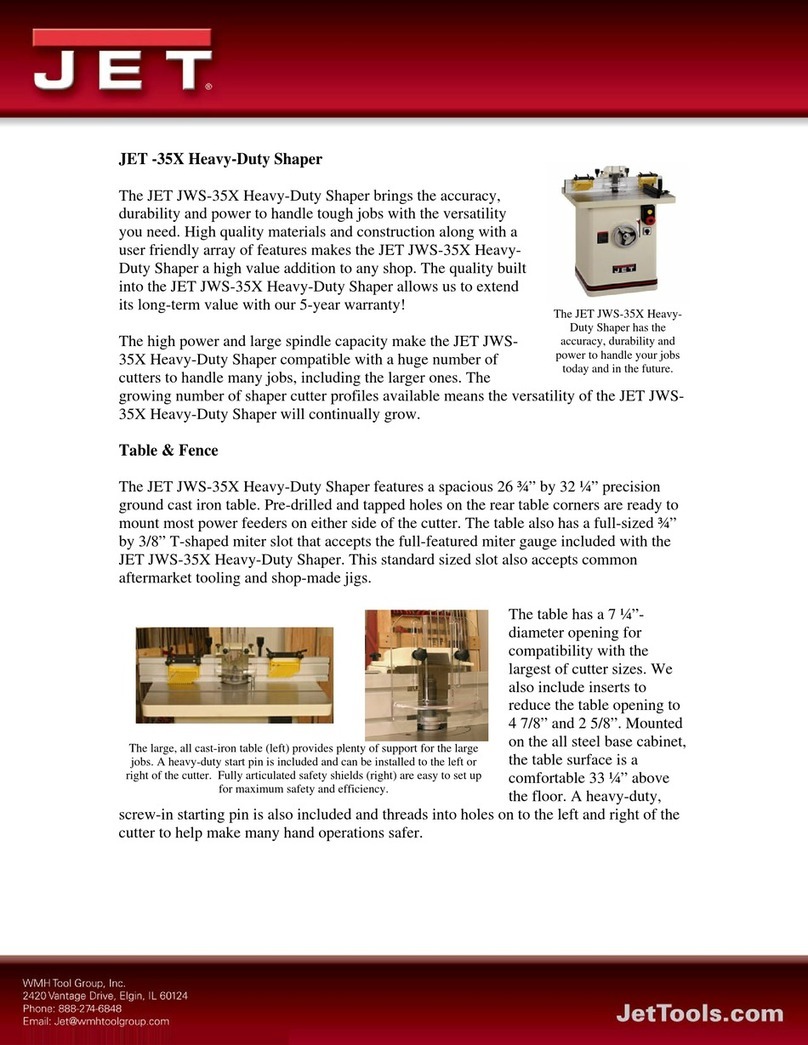
Jet
Jet JWS-35X Series Features
Ryobi
Ryobi LCS-180 user manual

