10 0.043 2.15 1.91 1.72 1.56 1.43 1.32 1.23
20 0.061 3.02 2.69 2.42 2.20 2.02 1.86 1.73
30 0.075 3.72 3.31 2.98 2.71 2.48 2.29 2.13
40 0.087 4.29 3.82 3.43 3.12 2.86 2.64 2.45
50 0.097 4.82 4.28 3.85 3.50 3.21 2.97 2.75
60 0.106 5.26 4.67 4.21 3.82 3.50 3.23 3.00
10 0.070 3.46 3.08 2.77 2.52 2.31 2.13 1.98
20 0.098 4.86 4.32 3.89 3.54 3.24 2.99 2.78
30 0.120 5.96 5.30 4.77 4.33 3.97 3.67 3.40
40 0.139 6.88 6.11 5.50 5.00 4.58 4.23 3.93
50 0.156 7.71 6.85 6.17 5.61 5.14 4.74 4.41
60 0.170 8.41 7.48 6.73 6.12 5.61 5.18 4.81
10 0.090 4.47 3.97 3.57 3.25 2.98 2.75 2.55
20 0.127 6.31 5.61 5.05 4.59 4.21 3.88 3.60
30 0.157 7.75 6.89 6.20 5.64 5.17 4.77 4.43
40 0.181 8.94 7.94 7.15 6.50 5.96 5.50 5.11
50 0.202 9.99 8.88 7.99 7.26 6.66 6.15 5.71
60 0.221 10.95 9.73 8.76 7.96 7.30 6.74 6.26
10 0.119 5.91 5.26 4.73 4.30 3.94 3.64 3.38
20 0.169 8.37 7.44 6.69 6.08 5.58 5.15 4.78
30 0.207 10.25 9.11 8.20 7.45 6.83 6.31 5.86
40 0.239 11.83 10.51 9.46 8.60 7.88 7.28 6.76
50 0.267 13.23 11.76 10.58 9.62 8.82 8.14 7.56
60 0.293 14.50 12.89 11.60 10.55 9.67 8.92 8.29
10 0.149 7.36 6.54 5.89 5.35 4.91 4.53 4.21
20 0.210 10.38 9.23 8.31 7.55 6.92 6.39 5.93
30 0.257 12.70 11.29 10.16 9.24 8.47 7.82 7.26
40 0.296 14.67 13.04 11.74 10.67 9.78 9.03 8.39
50 0.332 16.43 14.60 13.14 11.95 10.95 10.11 9.39
60 0.363 17.96 15.96 14.37 13.06 11.97 11.05 10.26
10 0.218 10.78 9.58 8.62 7.84 7.18 6.63 6.16
20 0.307 15.20 13.51 12.16 11.05 10.13 9.35 8.69
30 0.376 18.62 16.55 14.89 13.54 12.41 11.46 10.64
40 0.435 21.51 19.12 17.21 15.64 14.34 13.24 12.29
50 0.486 24.05 21.38 19.24 17.49 16.03 14.80 13.74
60 0.532 26.33 23.40 21.06 19.15 17.55 16.20 15.04
10 0.341 16.87 14.99 13.49 12.27 11.24 10.38 9.64
20 0.481 23.83 21.18 19.06 17.33 15.89 14.66 13.62
30 0.590 29.22 25.97 23.37 21.25 19.48 17.98 16.70
40 0.681 33.73 29.98 26.98 24.53 22.49 20.76 19.27
50 0.762 37.72 33.53 30.17 27.43 25.14 23.21 21.55
60 0.835 41.31 36.72 33.05 30.04 27.54 25.42 23.60
10 0.553 27.38 24.34 21.90 19.91 18.25 16.85 15.64
20 0.782 38.72 34.42 30.98 28.16 25.82 23.83 22.13
30 0.956 47.31 42.05 37.85 34.41 31.54 29.11 27.03
40 1.106 54.76 48.67 43.81 39.82 36.50 33.70 31.29
50 1.239 61.33 54.51 49.06 44.60 40.88 37.74 35.04
60 1.354 67.02 59.58 53.62 48.74 44.68 41.24 38.30
10 0.649 32.11 28.54 25.69 23.35 21.41 19.76 18.35
20 0.920 45.56 40.50 36.45 33.13 30.37 28.04 26.03
30 1.124 55.63 49.45 44.51 40.46 37.09 34.24 31.79
40 1.301 64.39 57.24 51.52 46.83 42.93 39.63 36.80
50 1.451 71.84 63.86 57.47 52.25 47.89 44.21 41.05
60 1.584 78.41 69.70 62.73 57.03 52.27 48.25 44.81
10 0.938 46.43 41.27 37.15 33.77 30.96 28.57 26.53
20 1.319 65.27 58.02 52.22 47.47 43.51 40.17 37.30
30 1.619 80.16 71.26 64.13 58.30 53.44 49.33 45.81
40 1.867 92.43 82.16 73.94 67.22 61.62 56.88 52.82
50 2.088 103.38 91.89 82.70 75.19 68.92 63.62 59.07
60 2.292 113.46 100.85 90.76 82.51 75.64 69.82 64.83
All application rates (gallons/acres) are estimates based on 0-28-0 (10.65 lbs/gallon) at 70 degrees F.
PumpRight Pressure Recommendations
(with 10 lb check valves):
• Minimum 20 PSI
• Maximum 80 PSI
Tower Electric Pump Pressure
Recommendations (with 4 lb check valves):
• Minimum 10 PSI
• Maximum 30 PSI
Chart is for 28-0-0 Fertilizer @ 70°
• Heavier fertilizers (like 10-34-0) will
have 5-15% less flow than chart
indicates for a certain pressure
• Cold fertilizers will cause system
pressure to increase at a given
application rate.
• Tower Electric Pump Systems will have
reduced flow and increased electrical
current draw due to cold fertilizer
increasing operating pressure. Use the
largest orifice possible for cold
weather operation.
B
Components
Liquid
30” Spacing
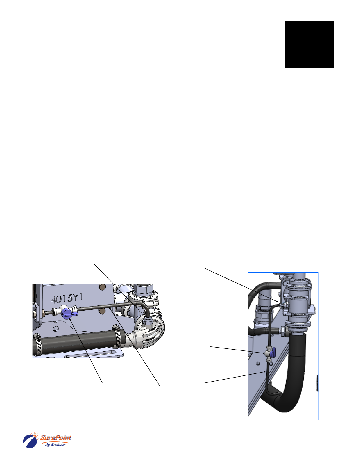
Remove top fitting
of each column.
Then push the
metering orifice into
bottom of each
outlet fitting. (This is
not used very
often.)
If using a metering
orifice in the flow
indicator, the orifice
replaces the ball
retainer. If not using
an orifice here, the
ball retainer must
be in place.
Ball
retainer Orifice
or