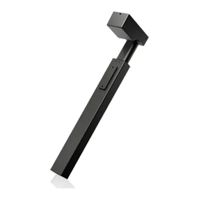
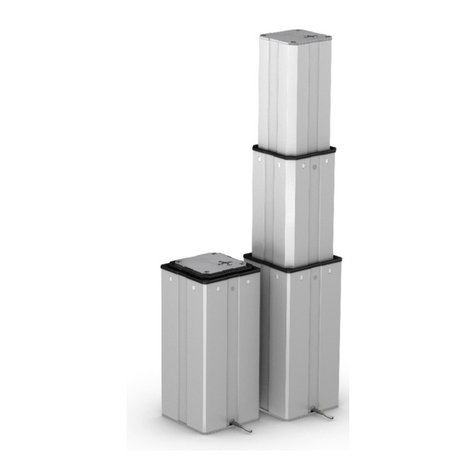
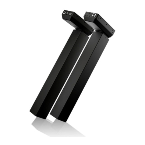
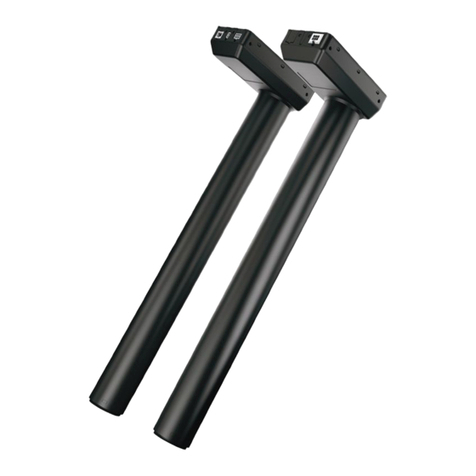
Suspa ELS3 User manual

SUSPA GmbH
Installation Instructions
English
ELS3 Lifting Column System (with Electrial
Components)
Read installation instructions carefully before initial use!
Follow the safety instructions!
This partly completed machinery is intended to be incorporated into
other machinery, other partly completed machinery/equipment or
to be joined with another framework so as to form a complete
machine as specified under the Machinery Directive. The machine
should be put into operation only after a conformity evaluation
procedure in accordance with the Machinery Directive has been
carried out for the complete machine.
No revision service applies to this documentation. The current
installation instructions are available at
http://www.suspa.com/global/downloads/

Information
ELS3 Lifting Column System –Installation Instructions Page 2
These installation instructions are a component of the technical documentation of the
system in accordance with the EC Machinery Directive.
These installation instructions correspond to the “Guideline 2006/42/EC of the European
Parliament and the Council for Adjustment of Legal and Administrative Regulations of
Member States for Machinery” (Machinery Directive).
These installation instructions are addressed to the person in charge who must pass it on
to the personnel responsible for the connection, use, and maintenance of the machine.
The person in charge must ensure that the installation instructions and the information
contained in the accompanying documents have been read and understood.
These installation instructions must be kept in a well-known and easily accessible location
and read in case of any doubt.
The manufacturer is not liable for injuries to people or animals and damage to objects or
to the machine itself arising from the improper/unauthorized use or by ignoring the
safety criteria contained in these installation instructions or by modification of the
machine or use of unsuitable spare parts.
The copyright for these installation instructions is held solely by
SUSPA GmbH
Mühlweg 33
90518 Altdorf
GERMANY
or its legal successor.
The contents of the user information is the intellectual property of SUSPA GmbH.
SUSPA GmbH expressly reserves the ownership of and copyright to the data contained in
the user information.
Reproduction and duplication, even in excerpts, are permitted only upon the written
consent of SUSPA GmbH.
Status: March 2019

Table of Contents
ELS3 Lifting Column System –Installation Instructions Page 3
1Information concerning this document....................................................................... 5
1.1 Structure of the warnings................................................................................................................... 5
1.2 Signal words and signal colors.........................................................................................................5
1.3 Symbols....................................................................................................................................................6
2Identification and notes................................................................................................... 7
2.1 Designation............................................................................................................................................. 7
2.2 Manufacturer.......................................................................................................................................... 7
2.3 Intended use...........................................................................................................................................7
2.4 Reasonably foreseeable misuse ....................................................................................................... 8
2.5 General instructions .............................................................................................................................9
3Safety instructions............................................................................................................. 11
3.1 Obligations..............................................................................................................................................11
3.2 Residual risk............................................................................................................................................12
3.3 Additional instructions ........................................................................................................................13
4Design and function......................................................................................................... 14
4.1 Technical specifications....................................................................................................................... 14
5Transport............................................................................................................................. 25
5.1 Safety instructions for transport....................................................................................................... 25
5.2 Transportation procedure..................................................................................................................25
6Installation .......................................................................................................................... 26
6.1 Safety instructions for installation ...................................................................................................26
6.2 Unpacking ...............................................................................................................................................26
6.3 Operating conditions........................................................................................................................... 30
6.4 Installation of components................................................................................................................31
6.5 Setting up and aligning the table....................................................................................................40
7Commissioning / Operation........................................................................................... 41
7.1 Warning notices for operation .........................................................................................................41
7.2 Tests prior to switching on the machine....................................................................................... 41
7.3 Duty Cycle ............................................................................................................................................... 42
7.4 Operation ................................................................................................................................................42
7.5 Faults and error indications...............................................................................................................45
8Service and maintenance................................................................................................ 46
8.1 General.....................................................................................................................................................46
8.2 Maintenance instructions ...................................................................................................................47
8.3 Maintenance...........................................................................................................................................47
9Decommissioning ............................................................................................................. 49
9.1 Switch off adjustment function.........................................................................................................49
9.2 Storing the lifting columns.................................................................................................................49
9.3 Disposal of components..................................................................................................................... 49

Table of Contents
ELS3 Lifting Column System –Installation Instructions Page 4
10 Spare parts ......................................................................................................................... 50
11 Appendix............................................................................................................................. 51
11.1 Index of Tables.......................................................................................................................................51
11.2 Index of Figures..................................................................................................................................... 52
11.3 Incorporation..........................................................................................................................................53

Information concerning this
document
ELS3 Lifting Column System –Installation Instructions Page 5
1Information concerning this document
1.1 Structure of the warnings
The combination of a signal word in conjunction with a pictogram classifies the respective warning.
The symbol can vary depending on the type of danger.
THE WARNING IS GIVEN BELOW A SIGNAL WORD THAT INDICATES THE
EXTENT OF THE EXISTING DANGER.
The first line after the signal word describes the type and source of the potential danger.
The following section describes the consequences if no measures are adopted to safeguard against
the danger.
The last paragraph describes the measures to avoid the danger.
1.2 Signal words and signal colors
The following signal words are based on DIN EN 82079-1 and ANSI Z 535.4, and are used in this
documentation. The safety colors have been taken from standard
ISO 3864-1.
Signal word
Use
Explanation
DANGER
Warning notice
Indicates a dangerous situation, which, if
ignored, leads to death or severe injuries.
WARNING
Warning notice
Indicates a dangerous situation, which, if
ignored, may lead to injuries and damage
to property.
CAUTION
Warning notice
Indicates a dangerous situation, which, if
ignored, may lead to minor injuries and
damage to property.
IMPORTANT
Note
Refers to ways to facilitate and simplify
operation and to cross-references. It
excludes the danger of damage to
property and the risk of injuries.
SAFETY INSTRUCTION
Safety
instruction
Draws attention to specific safety-relevant
instructions or procedures.
Table 1 Signal words and signal colors

Information concerning this
document
ELS3 Lifting Column System –Installation Instructions Page 6
1.3 Symbols
Some of the following special safety symbols according to DIN EN ISO 7010: 2011 are used in the
corresponding sections of these installation instructions and require particular attention depending on
the signal word and symbol combination:
Symbol
Use
Explanation
Note
Important information for
understanding the device or for
optimized operations.
Table 2 Symbols
1.3.1 Warning notice
Symbol
Explanation
Symbol
Explanation
General warning
sign
Warning against
hazardous electrical
voltage
Warning of hand
injuries
Table 3 Warning notice

Identification and notes
ELS3 Lifting Column System –Installation Instructions Page 7
2Identification and notes
2.1 Designation
ELS3 lifting column system (optionally with double-click function)
Consisting of:
ELS3 lifting column
Electrical controller
Hand switch
Connection cable
2.2 Manufacturer
SUSPA GmbH
Mühlweg 33
90518 Altdorf
GERMANY
2.3 Intended use
The SUSPA ELS3 lifting column system is used to adjust the height of work places in offices meant for
use in seated or standing position. Together with a specifically designed frame from the SUSPA GmbH
product range, the ELS3 lifting column system make up the table base frame for an office workbench.
The lifting column system is designed for load that applies pressure.
IMPORTANT Prior to installation or commissioning, ensure that the appropriate lifting column
system has been selected. Please note in this regard the technical specifications (see section 4.1
Technical specifications), in particular, the maximum load and adjustment range information.
Any other or advanced use of the lifting column system is deemed not to be in the manner intended
and thus improper. In this case, the safety and protective functions of the lifting column system may
be compromised.
This partly completed machinery is intended to be incorporated into other machinery, other partly
completed machinery/equipment or to be joined with another framework so as to form a complete
machine as specified under the Machinery Directive. The machine should be put into operation only

Identification and notes
ELS3 Lifting Column System –Installation Instructions Page 8
after a conformity evaluation procedure in accordance with the Machinery Directive has been carried
out for the complete machine.
SUSPA GmbH assumes no liability for damage resulting from such improper use.
Intended use also includes:
following all instructions in the installation instructions
following all the safety instructions
compliance with the maintenance intervals
2.4 Reasonably foreseeable misuse
Improper use that could result in risks posed to the user, third parties or to the lifting column system
in all operating modes includes the following:
using the lifting column system contrary to its intended use
installation of the lifting column system onto components that have not been
approved by SUSPA GmbH for this system
improper installation, commissioning, operation and maintenance of the system
operating the lifting column system beyond the physical operating limits described in
section "Operating conditions"
any modifications to the lifting column system as well as any add-ons or conversions
without prior consultation with the company, SUSPA GmbH
operating the lifting column system contrary to the instructions in the operating
manual, in particular the instructions on safety, installation, operation and faults
operating the lifting column system with apparent malfunctions and/or defects
WARNING
Risk of sustaining injuries due to unauthorized changes
Unauthorized modifications to the component as well as the use of spare parts from other
manufacturers (not original spare parts) may pose risks.
Do not allow any unauthorized or other modifications to the component without prior approval of
SUSPA GmbH.
IMPORTANT This equipment is not meant to be used by persons (including children) with limited
physical, sensory and mental capabilities or lacking experience and/or knowledge, unless they are
supervised by a person responsible for their safety or have received instructions from them about how
the equipment has to be used. Children must be supervised in order to ensure that they do not play
with the equipment.

Identification and notes
ELS3 Lifting Column System –Installation Instructions Page 9
2.5 General instructions
2.5.1 Warranty and liability
The "General Terms and Conditions" of SUSPA GmbH always apply. They have been made available to
the owner since the contract was signed at the latest.
Warranty claims and liability claims for personal injury and material damage are excluded if they are
attributed to one or more of the following causes:
Improper use of the component
Improper installation, commissioning, operation and maintenance of the component
Disregarding the information in the installation instructions
Unauthorized structural modifications of the lifting column system
Inadequate implementation of the prescribed maintenance operations
Disasters caused by external influence or force majeure
Repairs that have not been carried out by the manufacturer's specialists
Read the installation instructions carefully before using and putting the component into operation.
The installation instructions should familiarize the user with the handling of the components and
instruct the user in the details associated with function and maintenance. The installation instructions
must be made accessible to personnel at all times and must be kept available near the lifting column
system. The notes provided in the installation instructions regarding maintenance and operational
safety must be observed and complied with. SUSPA GmbH would be pleased to answer any questions
extending beyond the scope of these installation instructions.
2.5.2 Objectives of the installation instructions
These installation instructions serve as a support and contain all necessary instructions that must be
observed and complied with for general safety, transport, installation, operation, maintenance,
storage and disposal.
These installation instructions with all safety instructions as well as all additional documents of the
assemblies provided by external suppliers must be:
observed, read and understood by all persons working on the lifting column system;
this applies, in particular, to the safety instructions
easily accessible at all times to all persons
consulted even in case of the slightest doubt (safety)
Objectives:
Prevent accidents
Increase the service life and reliability of the components
IMPORTANT The right to technical modifications in the context of continuous product
improvement is reserved at all times without prior notification!

Identification and notes
ELS3 Lifting Column System –Installation Instructions Page 10
2.5.3 Target audience of the installation instructions
At different life cycle phases of the lifting column system, personnel with varied competences may
come into contact with the lifting column system.
Tasks
Specialized
personnel
Company SUSPA
GmbH
Private
person
Shipping (Delivery)
X
Transport
(Dispatching)
X
X
X
Commissioning /
Installation
X
X
X
Operation
X
X
X
Troubleshooting
X
X
X
Repairs
X
Decommissioning /
Dismantling
X
X
X
Table 4 Target group
Specialized personnel
Persons who can evaluate the work assigned to them and recognize possible dangers on the basis of
their specialized training, knowledge, experience and familiarity with the relevant standards.
External specialized personnel (SUSPA)
External specialized personnel are specifically trained for the manufacturer's products and are familiar
with every life cycle phase of the lifting column system. The life cycle phases from the transport up to
the hand-over to the operating company are usually carried out by external specialized personnel.
Private person
Persons with no previous knowledge in the field of installation of mechanical and electrical
components.
Outside the Federal Republic of Germany, the accident prevention regulations and safety provisions of
the respective country apply.

Safety instructions
ELS3 Lifting Column System –Installation Instructions Page 11
3Safety instructions
WARNING
Risk of sustaining injuries and damage to property
Risks are posed by ignoring the installation instructions and all safety instructions provided therein.
Read the installation instructions carefully before the initial commissioning. Fulfill and follow the
safety conditions required.
Observe and follow both the general safety instructions and also the special safety instructions
provided in the other sections.
The components have been constructed using state-of-the-art technology and in line with established
safety regulations. In order to prevent danger to life and limb of the user, third parties, or to the
component, use the components only for intended purpose and in perfect operating condition in
terms of safety.
The operator of the components or the persons assigned by the same are liable for property damage
and personal injury resulting from non-compliance with the instructions provided in the installation
instructions.
If there are any problems with the ELS3 lifting column system, immediately disconnect the controller
from the power supply and contact your dealer!
3.1 Obligations
WARNING
Risk of sustaining injuries by disregarding the safety symbols
A risk of sustaining injuries is posed by disregarding the warning notices provided in the area of the
component and in the installation instructions.
Heed all the warnings and safety notices in these installation instructions.
The following circumstances could increase the hazard potential of the components:
Hazard posed to persons through mechanical influences
Malfunctions that may impair the safety during operation of the components

Safety instructions
ELS3 Lifting Column System –Installation Instructions Page 12
3.1.1 Responsibilities of the operating company
This partly completed machinery is intended to be incorporated into other machinery, other partly
completed machinery/equipment or to be joined with another framework so as to form a complete
machine as specified under the Machinery Directive. The machine should be put into operation only
after a conformity evaluation procedure in accordance with the Machinery Directive has been carried
out for the complete machine.
3.2 Residual risk
IMPORTANT A residual risk is posed by inadvertent movement of the lifting column system. The
following are determined as potential causes for this matter:
Damaged cable
External influences (EMC)
Defects in the lifting elements, the controller or on the manual switch
Take the residual risk into consideration with the construction and while preparing
the operating instructions of the final product.
Operation with double-click function (with Hand switch Memory, see page 44)
WARNING
Risk of crushing and sustaining injuries to the hands, as well as damage to property.
An increased risk of being crushed or pinched is posed by automatic change of position of the lifting
column system via the double-click function (in particular, without the use of an anti-crushing
device).
Therefore, ensure that no objects or persons are in the danger zone (500 mm around the lifting
column system), and nobody reaches into the danger zone.
WARNING
Risk of sustaining injuries due to unsupervised traversing movements
By double-clicking a position memory key, the lifting column system automatically moves to the
memorized lifting column position. Persons or objects present in the danger zone are subject to an
increased risk of being crushed.
Therefore, keep a safety clearance of at least 500 mm during the automatic traversing movement.
Never leave the lifting column system unattended during automatic traversing movements.
IMPORTANT Observe the manuals and, in particular, the safety instructions and warnings of the
manual switch and the controller manufacturer: http://www.logicdata.net.

Safety instructions
ELS3 Lifting Column System –Installation Instructions Page 13
3.3 Additional instructions
Basically, the provisions of the accident prevention regulations of the professional association also
apply to all work on the lifting column system.
In addition, observe and follow
applicable and binding accident-prevention regulations
applicable and binding regulations at the place of use
recognized technical regulations for safe and professional working methods
existing environmental protection regulations
other applicable regulations

Design and function
ELS3 Lifting Column System –Installation Instructions Page 14
4Design and function
4.1 Technical specifications
Technical specifications –Lifting column system (overview)
Lifting column dimensions
Profile:
Square
Rectangle
Dual
telescopic
Single
telescopic
Dual telescopic
Position of bit tube:
BTU*
BTD**
BTU*
BTD**
BTU*
BTD**
Adjustment range (stroke):
650 mm
500 mm
650 mm
Compressed length:
565 mm
650 mm / 680
mm
565 mm
Extended length:
1215 mm
1150 mm /
1180 mm
1215 mm
Controllers (overview)
Input voltage:
230 V / 50 Hz
Standby use:
≤ 0.3 W
Performance data
Adjustment speed:
38 mm/s
35 mm /s
38 mm/s
35 mm/s
Lifting capacity:
see detailed description of the lifting column (page 15)
Table 5 Technical specifications (overview) * BTU: Big Tube Up
**BTD: Big Tube Down
IMPORTANT The designation of the respective model can be found on the rating plate of the
controller and the lifting column, e. g. “ELS3-650-BTD“ or “ELS3-473S-BTU”, etc.. It must be made sure
that the lifting columns are only operated with controllers with the same designation.

Design and function
ELS3 Lifting Column System –Installation Instructions Page 15
4.1.1 ELS3-650-BTU-Q lifting column (dual telescopic, big tube up, square)
Figure 1 ELS3-650-BTU-Q lifting column
View: Lifting column,
bottom
Technical specifications –ELS3-650-BTU-Q lifting
column
Dimensions:
Tube:
70/65/60 mm
Stroke:
650 mm
Compressed length:
565 mm
Extended length:
1220 mm
Weight:
approx. 7.0 kg
Lifting capacity:
50 kg / leg –SMART
60 kg / leg –
COMPACT
Max. speed:
38 mm/s
Length of motor cable:
1200 mm
Maximum static bending
moment:
150 Nm
Motor:
24 V DC
Table 6 Technical specifications ELS3-650-BTU-Q lifting
column

Design and function
ELS3 Lifting Column System –Installation Instructions Page 16
4.1.2 ELS3-650-BTD-Q lifting column (dual telescopic, big tube down, square)
Figure 2 ELS3-650-BTD-Q lifting column
View: Lifting column,
bottom
Technical specifications –ELS3-650-BTD-Q lifting
column
Dimensions:
Tube:
60/65/70 mm
Stroke:
650 mm
Compressed length:
565 mm
Extended length:
1215 mm
Weight:
approx. 7.0 kg
Lifting capacity:
50 kg / leg –SMART
60 kg / leg –
COMPACT
Max. speed:
38 mm/s
Length of motor cable:
1200 mm
Maximum static bending
moment:
150 Nm
Motor:
24 V DC
Table 7 Technical specifications ELS3-650-BTD-Q lifting
column

Design and function
ELS3 Lifting Column System –Installation Instructions Page 17
4.1.3 ELS3-500-BTU-Q lifting column (single telescopic, big tube up, square)
Figure 3 ELS3-500-BTU-Q lifting column
View: Lifting column,
bottom
Technical specifications –ELS3-500-BTU-Q lifting
column
Dimensions:
Tube:
70/65 mm
Stroke:
500 mm
Compressed length:
650 mm / 680 mm
Extended length:
1150 mm / 1180 mm
Weight:
approx. 6,10 kg
Lifting capacity:
60 kg / leg –SMART
Max. speed:
32-35 mm/s
Length of motor cable:
1200 mm
Maximum static bending
moment:
150 Nm
Motor:
24 V DC
Table 8 Technical specifications ELS3-500-BTU-Q lifting column

Design and function
ELS3 Lifting Column System –Installation Instructions Page 18
4.1.4 ELS3-500-BTD-Q lifting column (single telescopic, big tube down square)
Figure 4 ELS3-500-BTD-Q lifting column
View: Lifting column,
bottom
Technical specifications –ELS3-500-BTD-Q lifting
column
Dimensions:
Tube:
65/70 mm
Stroke:
500 mm
Compressed length:
650 mm / 680 mm
Extended length:
1150 mm / 1180 mm
Weight:
approx. 6,5 kg
Lifting capacity:
60 kg / leg –SMART
Max. speed:
32-35 mm/s
Length of motor cable:
1200 mm
Maximum static bending
moment:
150 Nm
Motor:
24 V DC
Table 9 Technical specifications ELS3-500-BTD-Q
lifting column

Design and function
ELS3 Lifting Column System –Installation Instructions Page 19
4.1.5 ELS3-650-BTU-RE lifting column (dual telescopic, big tube up, rectangular)
Figure 5 ELS3-650-BTU-RE lifting column
View: Lifting column,
bottom
Technical specifications –ELS3-650-BTU-RE lifting
column
Dimensions:
Tube:
67x107/61x101/55x95
mm
Stroke:
650 mm
Compressed length:
565 mm
Extended length:
1215 mm
Weight:
approx. 10 kg
Lifting capacity:
50 kg / leg –SMART
60 kg / leg –
COMPACT
Max. speed:
38 mm/s
Length of motor cable:
1200 mm
Maximum static bending
moment:
150 Nm
Motor:
24 V DC
Table 10 Technical specifications ELS3-650-BTU-RE
lifting column

Design and function
ELS3 Lifting Column System –Installation Instructions Page 20
4.1.6 ELS3-650-BTD-RE lifting column (dual telescopic, big tube down, rectangular)
Figure 6 ELS3-650-BTD-RE lifting column
View: Lifting column,
bottom
Technical specifications –ELS3-650-BTD-RE lifting
column
Dimensions:
Tube:
67x107/61x101/55x95
mm
Stroke:
650 mm
Compressed length:
565 mm
Extended length:
1215 mm
Weight:
approx. 10 kg
Lifting capacity:
50 kg / leg –SMART
60 kg / leg –
COMPACT
Max. speed:
38 mm/s
Length of motor cable:
1200 mm
Maximum static bending
moment:
150 Nm
Motor:
24 V DC
Table 11 Technical specifications ELS3-650-BTD-RE
lifting column
Other manuals for ELS3
2
Table of contents