BLACKHAWK! STL16 User manual

STL16
0
INSSTL16GB
REV: 05/14
JACK LIFT
STL16
INSTRUCTIONS MANUAL
(Original Instructions)

STL16
1
INDEX PAGE
1. WARNINGS – SAFETY INSTRUCTIONS 2
2. GENERAL INSTRUCTIONS 2
3.USE 3
4.IDENTIFICATIONDATA 3
5.PACKAGES 3
6. BACKING GROUND 3
7.MOVEMENT 3
8.OPERATINGAREA 4
9. POWER SUPPLY AND CONNECTION 5
10. INITIAL STARTING 5
11. TROUBLES, CAUSES AND REMEDIES 6
12.SAFETYDEVICES 6
13. TECHNICAL DATA 7
14. INDIVIDUAL PROTECTIONS 7
15.CHECKS AND MAINTENANCE 7
16.CLEANING 7
17. WARRANTY AND SPARE PARTS 8-14
18.SCRAPPING 15
19. MACHINE LOG 15
20. DECLARATION OF CONFORMITY 16

STL16
2
1.WARNINGS – SAFETY INSTRUCTIONS
READ THIS MANUAL CAREFULLY
BEFORE BEGINNING ANY WORKING MANOEUVRE AND COMPLY WITH THE SAFETY RULES
REGARDING THE LOAD MOVEMENT
SAFETY
•STL16 must be used only by personnel of full age, duly trained and authorised, been
provided with this instruction manual.
•The instruction manual must be read carefully and duly applied in any part.
•It is forbidden to use the machine to lift people.
•Before starting the lifting/lowering operations, make sure that the structure is clear of tools,
rags and objects of any kind.
•If there are electric cables in the operating area (because of working lights, portable tools,
etc.), be sure that they do not pass over the structure or rest on it, in order to avoid the risk
of cutting them and thus rendering the metal structure of the lift alive. This operation is
compulsory before using STL16.
•When positioning STL16 under the vehicle wheels, or under the vehicle under body (using
the supplied supports), make sure of the correct position of the lifting fork/support.
•Do not lift the load without being sure of the stability of the fork or the support.
•Do not lift the load before making sure of the efficiency of the inserted parking brake.
•Keep the load under observation, especially during the raise, to avoid incorrect inclinations
or troubles. If so, bring the load down and place the lift in such a way to have a balanced
distribution of the load.
•Comply with STL16 operating area established by the manufacturer.
•Clean the fork/support whenever it is dirtied to avoid the risk of load sliding.
•Never manipulate or unscrew any part of the lift, to avoid dangerous separations of the
parts.
•Always bring the load down to the round at the end of working hours, and avoid leaving the
lift loaded in standing position for a long period.
•Never exceed the maximum capacity of the lift Kg 1500.
•Once positioned the vehicle, always insert the safety pin in the column to hold the load.
2. GENERAL INSTRUCTION
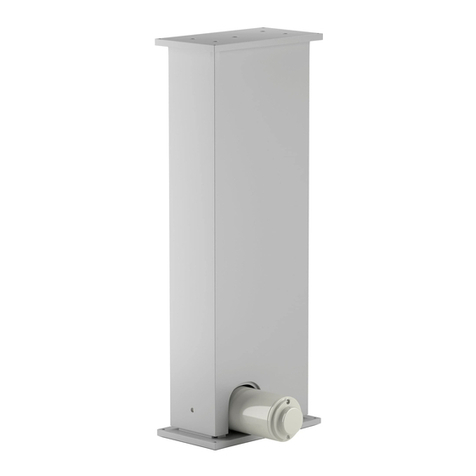
STL16 is a mobile hydraulic crick lift, with a column structure, built and manufactured to work at
wheel.
It offers the warranty of stability of the load both for raising and lowering operations.
The raise and descent are obtained using a sleigh fixed on a hydraulic cylinder that is operated
by a 350 bar hydraulic pump.
STL16 has reduced dimensions (see par.14 technical data) and a remarkable ease of handling,
obtained thanks to four wheels allowing an easy displacement.
The working operations are at man’s height.
The equipment is supplied with the manual and the CE certificate.
The CE certificate and the Manual must follow the equipment also in case of its sale, and must
be kept with the equipment.
STL16
3
3. USE
STL16 is for work-shops, tire-shops and body-shops for maintenances, checks, and car repairing.
It has not been built and it can not therefore be used to raise people.
STL16 must be used inside, protected from the atmospheric events (rain, humidity, wind).
The room temperature, in which the lift is installed, must be between +10° and 40°centigrade.
STL16 has not been thought for people operating under the lifted vehicle.
The non-respect of these rules in the use of STL16 can involve heavy risks for the operator, falling
only on his responsibility.
The user must employ the lift only in conformity with its use and all the instructions of the
manufacturer.
WARNING: The manufacturer and his distributors are not responsible for any possible
damages to people or things caused by an inappropriate and irresponsible use of the lift
different from the one described in this manual.
The first use of STL16 involves the implicit acceptance from the user of all conditions prescribed by
the manufacturer.
4. IDENTIFICATION DATA
The identification data of STL16 - the serial number, the capacity and the connection data - are
written on this manual and on the labels stuck on the structure.
The user must not take away, spoil or damage the labels on the structure.
The warranty automatically declines in case of their tampering.
5. PACKAGES
STL16 is packed with a column separated from the base.
When you open the packages check that the shipped parts correspond to all the STL16 parts and
check their integrity.
You must do this in front of the forwarder because the goods, unless different agreements
subscribed during the contract phase, travel at purchaser’s risk.
Any claim, for transport damages, caused by an incorrect load, unload and un-packaging, can not
be charged to the manufacturer company.
6. BACKING GROUND
The backing ground for this crick lift must be levelled, without depressions and with fit
characteristics to load support.
WARNING
The non-observance of this precise prescription can involve risks of the turnover of the load with
serious risks for people and things.
7. MOVEMENT
The move of the packages will be done according the safety rules and by personnel well trained in
this field. The staff must wear correct protective clothing.
It is forbidden to move the package in which the Lift is contained by hand.
STL16 is partially assembled.
It is possible to connect the feed hoses from the compressed air to the pump and from the pump to
the cylinder only after fixing the column to the base.

STL16
4
8. OPERATING AREA
STL16 must be used, for safety reasons, respecting its minimum area of pertinence, with a correct
distance from other equipment or from the walls of the working place.
We suggest defining this working area with strips on the floor or with special small columns
equipped of chains to avoid the access in the working area to unauthorised persons.
The prescription has the purpose to avoid the transit of people not assigned to the work, in the
safety area, when the load is lifted.
All the manoeuvres of lifting, stopping and lowering must be done at sight with a maximum
attention by the operator. Nobody must stay in the manoeuvre and pertinence area of the
equipment.
During the raising phase of the load STL16 will advance about 30 cm because of its lifting effect,
while during the descending phase there will be a withdrawing of the same distance (see picture
1). The raising and descending operations must be done by an operator who has a free escape.
PICTURE N°1

STL16
5
9. POWER SUPPLY CONNECTION
The connections that follow must be performed with the lift in off position:
•Connect the pump flexible hose to the cylinder verifying that the coupling is correctly
inserted.
•Replace the hermetic plug of the reservoir by the special plug with oil dipstick.
•Connect the flexible hose, coming from the pneumatic supply, to the pump – be sure that
the inlet pressure is between 8 to 10 bars. Check that the pneumatic system has been
prepared with a correct condensate drying system.
10. INITIAL STARTING AND OPERATION
After learning the control functioning, connect the power supply and proceed with the following
actions:
RAISING:
•Be sure of the efficiency of the parking brake before lifting the vehicle.
•Be sure of blocking the vehicle using the parking brake.
•Position the lift in such a way that the fork completely fits to the tire sides. If you use a
clamp to repair the vehicle sheet, be sure of its correct positioning.
•Be always sure of the correct positioning of the lifting arm before lifting the load.
•Press the pump pedal - side A (see picture 2) - to lift the vehicle to the desired height.
•After reaching the desired height, release the pedal and put the load under safety inserting
the supplied pin in the hole in the column.
•Press the pump pedal - side B (see picture 2) - to let the trolley of the lift lean on the safety
pin.
WARNING
Do not raise the jack until the maxi height to avoid going up to the end of cylinder stroke
LOWERING:
•Press the pump pedal – side A (see picture 2) to release the trolley from the safety pin.
•Take the safety pin away from the hole where it was inserted in.
•Press the pump pedal – side B (see picture 2) to lower the vehicle at the desired height or
to the ground.
•Take the lift away from the vehicle.
•Now you can move the vehicle away.
WARNING
After working, or when not used for a longer period, the lift STL16 must be brought to its rest
position.
Never leave the load in upper or in standing position without operator.
PICTURE 2

STL16
6
11. TROUBLES, CAUSES AND REMEDIES
The following is a list of the possible troubles, their causes and remedies.
If the problem is not included in the list, stop the use of the lift and immediately contact the
manufacturer or the authorised dealer to receive appropriate instructions.
It is recommended to employ trained personnel to avoid manipulation of the lift or its controls.
TROUBLES CAUSES REMEDIES
stops while lifting There are obstacles in the
lifting column
Bring the load down, turn off the
power supply and remove the
obstacle
The controls are on but
the crick-lift does not
function
Excessive load
The silencer is blocked
The air supply is not enough.
Check the load weight and follow the
manufacturer instructions.
Clean or replace the silencer
Check that the air supply is between
8 and 10 bars
The crick-lift comes down
without using the pump
controls
Dirt in the pump release valve Contact the manufacturer before
making any reparation
Oil leaking from the
pump
Wearing of the grommets Contact the manufacturer before
making any reparation
Oil leaking from the
flexible hose
Wearing or cutting of the hose Replace the flexible hose
Oil leaking from
couplings
Wearing or defect of the
coupling
Replace the detective coupling
WARNING
In case of breakdown of the hydro pneumatic pump, it is forbidden and dangerous to replace it by
another pump of other type that the one supplied with the equipment. The use of a pump of
another type can be at the origin of serious accidents and/or deterioration of the components of the
jack.
Do not modify the regulations of the maximum pressure of the pump (350 bar)
The reparation of the hydro pneumatic pump and the cylinder requires specify knowledge and must
be made only by a Blackhawk repair centre.
12. SAFETY DEVICES
Safety pin of the lifting trolley: it must be inserted before making any operation with load lifted.
This pin blocks the descent of the trolley in the event of the accidental breaking of the chain.
Descent control valve on the pump: to allow a smoother descent of the crick-lift.
Parachute valve: Prevents the descent of the trolley in case of hydraulic hose breaking.
WARNING
Remember that it is good behaviour to bring the load down in case of a long standing.
When the lift is in use the operative area must be completely free from any obstacle and people not
related to the operation of repairing/maintenance.

STL16
7
13. TECHNICAL DATA
Weight of the lift with pump 85 Kg
Maximum lifting capacity 1.500 Kg
Vehicle max. load 3.000 Kg
Maximum lifting height 995 mm
Lift height 1.330 mm
Lift width 660 mm
Lift length 1.010 mm
Functioning Hydro-pneumatic
Hydropneumatic pump setting 350 Bar
Sound level of pump 72 dB(A)
14. INDIVIDUAL PROTECTIONS
The operator must always use protective work clothing as established by the law and must adopt
all the safety procedures which are compulsory in work places.
When using STL16 the operator must follow the standard law, the company procedures and his
good sense, for his own protection, the protection of people and things according to the
instructions written in this manual.
15. CHECKS AND MAINTENANCE
All the checks must always be when the power supplies are off and the lift not in operation.
The check must be at sight since STL16 does not compel the operator to do a special
maintenance.
Clean the air silencer exhaust of the pump every 6 months with the air pressure. Replace it
if necessary.
Periodically check the flexible hose and the fast couplings.
Periodically check the oil level in the pump.
Replace the hydraulic oil every 12 months, or more in relationship to the frequency of use.
Use BLACKHAWK hydraulic oil LX22X (1 litter) or LX22Y (5 litters)
CAUTION
The worn oil must be eliminated according to the local Environmental
rules.
Grease the internal part of the column (where the trolley slides on) every 3 months.
These simple procedures will preserve the lfit from troubles and defectsduring use.
16. CLEANING
Clean STL16 with care at least one a week, removing dirt, dust and any possible smearing
substances. Use self-cleaning cloths. Do not use water, inflammable or corrosive liquids.

STL16
8
17. WARRANTY AND SPARE PARTS
Every part of STL16 is covered by a 12 month warranty; this warranty will not be applied in case of
tampering or if the serial numbers or any other identifiable data of the machine printed on the label
have been damaged or removed.
With the exception of the cases covered by warranty or of parts subjected to normal wearing and
tearing, the manufacturer reserves the right to satisfy the customers’ request in relation to the
extent of the damage and to the possible restoration of STL16 to its mechanical and operative
safety standard.
The after-sale services under warranty are included by law.
STL16 EXPLODED VIEW

STL16
9
ITEM PART
NUMBER DESCRIPTION Q
1 S885A356 CHAIN PROTECTION 1
2 S061A177 PIN FOR PULLEY 1
3 S044A058 RETAINING RING 4
4 S046A065 SCREW M5X16 7
5 S098A048 TOP COVER 1
6 MBBF415 SCREW M4X10 2
7 S070A067 HANDGRIP 2
8 S066A017 CHAIN 1
9 S885A358 LONG FASTENING FOR CHAIN 1
10 S061A179 SAFETY PIN 1
11 S037A115 CHAIN SUPPORT 1
12 S055A066 NUT 2
13 S046A064 SCREW 6
14 S885A355 STANDOFF 1
15 S108A071 WASHER 3
16 S096A158 NIPPLES 1
17 S190A047 PARACHUTE VALVE 1
18 S108A070 WASHER 8
19 MBEF609 SCREW M6X10 2
20 S037A117 PUMP CONTAINER 1
21 S028A204 SCREW 2
22 S106A054 SWIVEL WHEEL 2
23 S055A065 NUT 2
24 S044A059 RETAINING RING 4
25 S106A055 WHEEL 2
26 S061A178 PIN FOR WHEEL 2
27 S005A024 BASE FRAME 1
28 S037A116 CYLINDER PIN 1
29 S950A791 COLUMN 1
30 S900A915 CYLINDER - COMPLETE 1
31 S019A010 PULLEY 1
32 S107A035 AXLE 1
33 S885A357 SHORT FASTENING FOR CHAIN 1
34 S950A792 COMPLETE TROLLEY 1
35 STL1603 FORK FOR WHEEL 1
36 STL1604 PINCH WELD ADAPTER 1
37 S646A157 OIL HOSE 1

STL16
10
CYLINDER EXPLODED VIEW
ITEM PART
NUMBE
R DESCRIPTION Q
30a S030A038 CYLINDER 1
30b S489A014 SELF-LOCKING RING 1
30c•S076A001 PACKING 1
30d S063A062 PISTON 1
30e•S041A035 O-RING 1
30f S489A015 RING NUT 1
30g S149A094 PISTON ROD 1
30h S410A105 RAM ATTACHMENT 1
NOTE: •In repair kit RKTS900A915
S900A915

STL16
11
TROLLEY EXPLDED VIEW
ITEM PART
NUMBER DESCRIPTION Q
34a S190A048 TROLLEY BODY 1
34b S101A873 UPPER GIB PLATE 2
34c MBBF821 SCREW M8X20 8
34d S101A872 LOWER GIB PLATE 2
34e S107A034 BEARING 4
34f S108A072 WASHER 4
34g S036A008 FERRULE 4
S950A792

STL16
12
PUMP EXPLODED VIEW

STL16
13
ITEM PART
NUMBER DESCRIPTION
0 S028A204 SCREW
1 S885A359 SMALL FOOT
2 S025A009 TANK
3■S076A016 PACKING
4 S044A061 RETAINING RING
5 S018A011 FILTER
6 S885A361 FILTER FASTENING
7 S108A071 WASHER
8 S016A005 BALL
9 S190A049 PUMP BODY
10 S190A051 MAX PRESSION VALVE
11 S885A364 SPRING STOP
12 S110A052 SPRING
13 S013A024 SPRING GUIDE
14 S016A006 BALL
15 S046A066 SCREW M6X10
16 S108A075 WASHER
17■S076A011 PAPER PACKING
18 S108A074 WASHER
19 S051A011 PLUNGER (300 BAR)
20■S076A008 PACKING (300 BAR)
21 S107A036 BRONZE BEARING (500 BAR)
22 S006A024 PLUG (300 BAR)
23■S076A014 PACKING
24 S110A047 SPRING
25 S041A036 CUP (300 BAR)
26 S051A012 PLUNGER
(300 BAR)
27■S076A013 PACKING
28■S076A002 PACKING
29 S006A028 PLUG
30 S051A014 PLUNGER
31■S076A012 PACKING
32 S051A013 REVERSER PISTON
33■S076A015 PACKING
34 S046A067 SCREW M6X25
35 S030A039 CYLINDER
36■S076A009 PAPER PACKING
37■S076A010 PAPER PACKING
38 S110A050 SPRING

STL16
14
39■S076A003 PACKING
40 S046A064 SCREW M4X8
41 S041A037 PACKING CUP
42■S076A007 PACKING
43 S006A027 PLUG
44 S885A365 AIR BLOCK
45■S076A005 PACKING
46 S010A002 NEEDLE
47 S046A068 SCREW M6X35
48 S885A363 RUBBER SILENCER
49 S885A362 NYLON SILENCER
50 S885A360 OIL BLOCK
51 S061A180 OIL UNLOADED PIN
52 S110A051 SPRING
53 S006A023 PLUG
54 S305A010 STUD
55 S006A026 PLUG
56 S010A001 UNLOADED NEEDLE
57 S190A052 NO RETURN VALVE
58 S190A053 RELEASE VALVE
59 S061A183 PIN
60 S016A005 BALL
61 S110A049 SPRING
62 S016A008 BALL
63 S013A025 BALL GUIDE
64■S076A004 PACKING
65 S110A048 SPRING
66 S061A182 AIR BLEEDED PIN
67 S076A006 PACKING
68 S110A053 SPRING
69 S108A073 WASHER
70 S044A060 RETAINING RING
71 S006A029 PLUG WITH GAUGE
72 S098A049 TANK PLATE
73 15G.01 STUD
74 S190A050 PUMP COVER
75 S028A204 SCREW
76 S061A181 PEDAL PIN
77 S044A062 RING
78 S218A002 PEDAL
NOTE:■In repair kit RKTSTL1602

STL16
15
18. SCRAPPING
If the lift or some of its parts are scrapped, respect the laws concerning waste disposal and when
possible recycle part of it.
Each part must be scrapped according to its typology.
19. MACHINE LOG
It is advisable to use the following scheme to note the maintenance of STL16 and any repairs
carried out on the machine.
This will allow the operator to have correct information on the functioning of the machine.
Serial number date of manufacturing
………………….
…………………………
Date Repairs or scheduled
maintenance Spare parts used Operator’s
signature

STL16
16
20. DECLARATION OF CONFORMITY

STL16
17
BLACKHAWK SA (International Sales)
All rights reserved BP 5 – 67026 Strasbourg Cedex -FRANCE
Tel: +33 3 88 65 76 30 – Fax: +33 3 88 65 76 31
E-Mail:[email protected]
BLACKHAWK SA FRANCE – BENELUX
BP 5 – 67026 Strasbourg Cedex – FRANCE
Tel: 03 88 65 76 30 – Fax: 03 88 65 76 31
E-Mail : [email protected] / [email protected]
BLACKHAWK SA DEUTSCHLAND – SCHWEIZ - ÖSTERREICH
BP 5 – 67026 Strasbourg Cedex – FRANCE
Tel: +33 3 88 65 76 30 – Fax: +33 3 88 65 76 31
SNAP-ON EQUIPMENT SRL – BLACKHAWK ITALIA
Via Provinciale Carpi 33 – I-42015 Correggio – RE - ITALY
Tel: 0522 733620 – Fax: 0522 733621
E-Mail: blackhawk-italia@snapon.com
Table of contents
Popular Lifting Column manuals by other brands

progressive automations
progressive automations FLT-03-2-1 user manual

Phoenix Mecano
Phoenix Mecano RK Rose+Krieger Multilift II Assembly instructions

Linak
Linak DL15 user manual

Phoenix Mecano
Phoenix Mecano DewertOkin DC20 installation instructions

stertil-KONI
stertil-KONI ST 1055 Installation, operation & service

Vynckier
Vynckier HB240CF manual