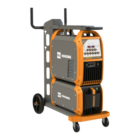
Svarog ARC 160-PFC User manual

ARC 160-PFC Welding Machine
USER MANUAL
REVISION : 2016-03-30


Preface
Thi manual include hardware de cription and operation introduction of ARC 160-PFC equipment.
For your and other people’ afety, plea e read the manual carefully.
Pay attention
Pay attention to the word after the ign below.
Sign Description
The word after thi ign mean there i great potential danger,
which may cau e major accident, damage or even death, if it i not
followed.
The word after thi ign mean there i ome potential danger,
which may cau e hurt or property lo e, if it i not followed.
The word after thi ign mean there i potential ri k, which may
cau e equipment fault or break, if it i not followed.
Version
Ver ion YF-TAE-0001, A0, relea ed at 30th, 03, 2016.
The content of thi manual are updated irregularity for updating of product. The manual i only
u ed a operation guide, except for other promi e . No warrantie of any kind, either expre or
implied are made in relation to the de cription, information or ugge tion or any other content of
the manual.
1

CONTENTS
1 Safety warning
2 Product
2.1 General
2.2 Technical data
3 In tallation
2

1 Safety warning
The afety note li ted in thi manual i to en ure correct u e of the machine and to keep you
and other people from being hurt.
The de ign and manufacture of welding machine con ider afety. Plea e refer to the afety
warning li ted in the manual to avoid accident .
Different damage would be caused by wrong operation of the equipment as follows. Please read the user
manual carefully to reduce such damage.
Sign Description
Any contact of electric parts may cause fatal electric shock or urnt.
Gas and fumes are harmful to health.
Operation in narrow space may cause choke .
Spark and hot workpiece after welding may cause fire.
Bad connected ca le may cause fire.
Uncompleted connection of workpiece side circuit may cause fire.
Never weld on the case of tinder stuff, or it may cause explode.
Never weld airtight containers such as slot, pipe etc., or it may reak.
Arc ray may cause eye inflammation or skin urnt.
Spark and residue will urn your eyes and skin.
Toppling over of the gas cylinder will cause ody hurt.
Wrong use of the gas cylinder will lead to high-pressure gas eruption
and cause human hurt.
Never let fingers, hair, clothes or etc. near the moving parts such as
the fan.
The wire shoot out of the torch may sta eyes, face and other naked
parts.
Never stand in front of the swang equipment or under it, or it may fail
and cause injury.
3

Please follow the rules elow to avoid heavy accidents.
Never u e the equipment to do other thing but welding.
Follow related regulation for the con truction of the input-driven power ource, choice of
place, u age of high-pre ure ga , torage, configuration, afe-keeping of workpiece after
welding and di po al of wa te, etc.
None ential do not enter the welding area.
People u ing heart pacemaker i not allowed to get clo e to the welding machine or area
without doctor’ permi ion. The magneti m created by energizing the welding machine
can have a bad effect to the pacemaker.
In tall, operation, check and maintain the equipment by profe ion per onnel.
Under tanding the content of the u er manual for afety.
Please follow the rules elow to avoid electric shock。
Keep away from any electric part .
Earth the machine and workpiece by profe ional per onnel.
Cut off the power before in tallation or checking, and re tart 5 minute later. The
capacitance i chargeable device. Plea e en ure it ha no voltage before tart again even
if the power ource i cut off.
Do not u e wire with inadequate ection urface or damage in ulation leeve or even
expo ed conductor.
Do en ure well i olation of wire connection.
Never u e the device when the enclo ure i removed.
Never u e broken or wet in ulation glove .
U e firenet when work at high po ition.
Check and maintain regularly, don’t u e it until the broken part are fixed well.
Turn off the power when not in u ed.
Follow the national or local related tandard and regulation when u ing the AC welding
machine at narrow or high po ition.
Please follow the elow notes to avoid fire and explode, etc.
No combu tible in welding area.
Keep off combu tible when welding.
Keep hot workpiece after welding away from flammable ga .
4

Do move away the combu tible around when weld the dooryard, ground and wall,.
The wire connection of ba e metal hould be a clo e to the welding place a po ible.
Never weld tho e facilitie with ga pipe or airtight lot.
Put fire extingui her around the welding area to prevent fire.
The gas and fumes are harmful to health, please wear protective
device according to regulations.
Wear exhau t equipment and breathe preventive facilitie to prevent ga poi oning or
choke.
U e ugge ted part exhau t equipment and breathe preventive facilitie to prevent hurt or
poi oning by ga and other powder, plea e.
To prevent oxygen-deficiency, air out the ga -filled room which i full of CO2 and argon on
the bottom, When operating on trunk , boiler , cabin , etc.
Plea e accept the upervi or’ in pection when operating in narrow pace. Air the room
and wear breathe preventive facilitie .
Never operate in degrea e, wa hing or pray pace.
U ing breathe preventive facilitie when weld hielded teel for it will cau e poi onou du t
and ga .
The arc, spark, residue and noise are harmful to health, please wear
protective appliance.
Eye protection again t arc i recommended when welding or upervi e welding.
Plea e wear preventive pectacle .
Welder’ glove , welder’ goggle , long leeve clothe , leather apron, and other tandard
protection equipment mu t be worn for welding operation.
A creen to protect other people again t the arc mu t be et in the welding place.
Please follow the notes elow to avoid gas cylinder toppling over or
roken.
U e the ga cylinder correctly.
U e the equipped or recommended ga eou regulator.
5

Read the manual of ga eou regulator carefully before u ing it, and pay attention to the
afety note .
Fix the ga cylinder with appropriate holder and other relative part .
Never put the cylinder under high temperature or un hine environment.
Keep your face away from the ga cylinder exit when opening it.
Put on the ga hield when it i not u ed.
Never put the torch on the ga cylinder. The electrode can not meet the ga cylinder.
Any touch of the switch part will cause injury, please note the
following.
Never u e the machine when the enclo ure i off.
In tall, operate, check and maintain the machine by profe ional per on.
Keep your finger , hair, clothe etc. away from the witch part uch a the fan.
The wire end may deal damage, please note the following.
Never look into the electric conduction hole when checking the wire feeding i normal or
not, , or the hooting wire may tab your eye and face.
Keep your eye , face or other naked part away from the end of torch when feeding the
wire manually or pre ing the witch.
For etter work efficiency and power source maintenance, please
note the following.
Precaution again t toppling over.
Never u e the welding equipment for pipe thawing.
Lift the power ource from ide when u e the up-down forklift truck to avoid toppling over.
When u ing the crane for lift, tie the rope to the ear with an angle no more than φ15 to the
vertical direction.
When lifting the welding machine which equipped with ga cylinder and wire feeder,
download them from the power ource and en ure the horizontal of the machine. Do fix the
ga cylinder with belt or chain when moving it to avoid body hurt.
En ure fa tne and in ulation when lifting the wire feeder through the wing ring for
6

welding.
Electromagnetic interference needing attention:
It may need extra preventive mea ure when the equipment i u ed in particular location.
Before the in tallation, plea e e timate the potential electromagneti m problem of the
environment a follow .
a) Upper and lower part of the welding equipment and other nearby power cable, control
cable, ignal cable and phone cable.
b) Wirele electric a well a TV radiation and reception equipment.
c) Computer and other control equipment .
d) Safety-recognition equipment etc. Such a upervi e of indu trial equipment .
e) Health of people around. Such a per onnel u ing the heart pacemaker or audiphone.
f) Equipment for adju tment and mea urement.
g) Anti-di turb capability of other u ed equipment .U er hould en ure the e equipment
and the environment are compatible, which may need extra preventive mea ure .
h) Practical tate of the welding and other activitie .
U er hould ob erve the following do and don’t to decrea e radiation interference.
a) Connect the welding equipment to the power upply line .
b) Maintain the welding equipment regularly.
c) The cable hould be hort enough to be clo e to each other and the ground.
d) En ure the afety of all the welding metal part and other part nearby.
e) The workpiece hould be well earth.
f) Shield or protect the other cable and equipment to decrea e the effect of di turbance .
The welding equipment can be complete hielded in ome pecial condition .
U er are re pon ible for interference due to welding.
7

2 Product
2.1 General
The welding machine applie the mo t advanced inver ion technology in the world.
The principle of inver ion i to tran form the power frequency of 50Hz/60Hz into direct current
and invert it into high frequency (25KHz) through high-power device IGBT, then perform
voltage-drop and commutation with the output high-power D.C power upply via Pul e Width
Modulation (PWM). Since the witch power inver ion technology i adopted, the weight and
volume decrea e greatly while the conver ion efficiency increa e of more than 30%
The machine ha the function of STICK and TIG. It adopt full digital panel di play, which can
realize ynergic adju tment and welding voltage a well to regulate the welding parameter
ea ily.
Thank your for choo ing our product . Plea e feel free to propo e your valuable ugge tion ;
we will make effort to perfect our product and ervice.
The machine is mainly used in industrial fields. It will cause radion interference if used
indoors. Please take through precaution measures.
8

2.2 Technical data
Mode
Parameters
Arc 160-PFC
Power voltage (V) 1 pha e AC95V~265V
Frequency (Hz) 50/60
Rated input current (A) 28
No-load voltage(V) 71
Output current adju tment (A) 95-180V 20-110(MMA)
5-110(TIG)
180-265V 20-160(MMA)
5-160(TIG)
Rated Output voltage (V) 20.8-26.4(MMA)
10.2-16.4(TIG)
Duty cycle (%) 20
Power factor More than 0.95
Efficiency (%) More than 84
In ulation grade F
Hou ing protection grade IP23S
Weight (kg) 6
Welding thickne (mm) More than 0.8
Overall dimen ion (mm) 351*145*253
9

3 Installation
The welding equipment i equipped with power voltage compen ation device. It keep the
machine work normally when power voltage fluctuating at AC95V~AC256V of rated voltage.
When u ing long cable, in order to reduce voltage drop, big ection cable i ugge ted. If the
cable i too long, it will affect the performance of arcing and other y tem function, it i
ugge ted to u e the recommend length.
Make ure the intake of the machine i not covered or blocked to avoid the malfunction of
the cooling y tem.
U e ground cable who e ection no le than 6mm2 to connect the hou ing and earth. The
method i to connect the grounded interface in the back to the earth device, or make ure
the earth end of power interface ha been reliably and independently grounded. Both way
can be u ed together for better ecurity.
Arc 160-PFC Installation Procedures:
Correct Installation of LIFT TIG
a) Connect the hielded-ga ource correctly. The ga upplying route hall include ga
cylinder, argon decompre ion flow meter and ga pipe. The connecting part of the ga
pipe hould be fa tened by ho e clamp or other object , in order to prevent leakage and air-
in.
) Connect the plug of TIG torch to “-“of the front panel, and fa ten it clockwi e.
c) Connect the plug of TIG torch to the relative interface of panel and fa ten the crew.
d) Connect one end of the earth clamp cable to “+” of the front panel, and fa ten it clockwi e,
the other end clamp the workpiece.
Correct Installation of STICK
a) Make ure cable with electrode holder and quick plug connected well. Connect the quick
plug to the ocket “-” of the machine, and fa ten it clockwi e tightly.
b) Connect the quick plug at one end of the cable into the ocket “+” of the machine, and
fa ten it clockwi e, the other end clamp the workpiece.
c) Plea e pay attention to the connecting terminal, DC welding machine ha two connecting
way : po itive connection and negative connection. Po itive connection: holder connect
with “-” terminal, while work piece with the “+” terminal. Negative connection: work piece with
the“-” terminal, holder with the “+” terminal. Choo e uitable way according to the working
ituation. If un uitable choice i made, it will cau e un table arc, more patter and
conglutination. If uch problem occur, plea e change the polarity of the fa tened plug. It
10

hould adopt negative connection when welding with alkaline electrode, while po itive
connection when welding with acid electrode.
This procedure shall e operated y electrician!
Connect proper power cable to the di tribution box with corre ponding capacity according to
the input voltage and current (See technical parameter table). Do not connect to the
inappropriate voltage and make ure that the difference of power upply i within permitted
range.
Installation drawing of Arc 160-PFC (LIFT TIG)。
Installation drawing of Arc 160-PFC (STICK)。
11

4 Operation
4.1 Front panel layout
1 -STICK/LIFT TIG witch key
2 -Multifunctional data di play
3 -Multifunctional data adju ting knob(coar e adju tment by pre ing the knob and turning it:
big regulating rate and high peed; fine adju tment only by turning the knob: mall
regulating rate and low peed)
4.2 Operation Instruction
The starting up display
Switch on the welding power ource, the front panel di play a Chart 1. After
the
【Multifunctional data di play】
(or any key or knob on front panel) fla he for 5 econd , the
machine enter into the welding mode that aved in the la t hutdown.
Chart 1: the tarting-up di play interface
12

Operation instruction under STICK mode.
a) When welding top , Pre the【STICK/LIFT TIG witch key】,the STICK indicator light
up,and it turn into STICK mode.
) under STICK mode ,Adju ting the 【Multifunctional data adju ting knob 】can change the
welding current during welding proce , and di played in 【multifunctional data di play】.
【multifunctional data di play】how the pre et current“080A”, it unit i ampere(A).
Chart 2: under STICK mode, pre et current di play with VRD enabled
c) 5 econd later after etting the welding parameter , the 【multifunctional data di play】
would fla he for one time, which mean the data ha been aved. Moreover, the panel
would di play the e data when re tart the machine next time if the parameter keep
unchanged.
d) When the input voltage i 95V~180V ,then current adju tment range i 20A~110A.And
when the input voltage i 180V~265V ,the current adju tment range i 20A~160A.
Operation instruction under LIFT TIG mode.
a) When welding top , pre the
【STICK/LIFT TIG witch key】,the LIFT TIG indicator light
up,and it turn into LIFT TIG mode. LIFT TIG mean the tung ten contact the workpiece
fir t, then the arc i ignited by lifting the torch.
b) Under LIFT TIG mode, Adju ting the 【Multifunctional data adju ting knob】can change the
welding current during welding proce , and di played in 【multifunctional data di play】.
【multifunctional data di play】how the pre et current“080A”, it unit i ampere(A).
13

Chart3: The pre et current under LIFT TIG mode
c) 5 econd later after etting the welding parameter , the 【multifunctional data di play】
would fla he for one time, which mean the data ha been aved. Moreover, the panel
would di play the e data when re tart the machine next time if the parameter keep
unchanged.
d) When the input voltage i 95V~180V, the current adju tment range i 5A~110A.And when
the input voltage i 180V~265V, the current adju tment range i 5A~160A.
Note :The machine adopt touched ignition way when perform welding under TIG mode.
Fir tly make ure the tung ten contact the workpiece completely, then pre the torch
witch, lifting up the torch to ignite arc ucce fully.
Malfunction display
a) Malfunction di play of over-current
The panel di play a Chart 4 when over-current, and the
【multifunctional data di play】
fla he
continuou ly, the machine can not work normally. Re tart the machine, the panel would di play
the parameter that were et before malfunction occurrence.
Chart 4: Malfunction di play of over current
14

b) Malfunction di play of overheating protection
The panel di play a Chart 5 when overheating, and the
【multifunctional data di play】
fla he
continuou ly, the machine can not work normally. Only when the temperature of the welding
machine fall below 60 , the overheating malfunction would di appear, and the machine work℃
normally without re tarting.
Chart 5:Malfunction di play of overheating protection
c) Malfunction di play of over-voltage and le -voltage protection
The panel di play a Chart 6 when over-voltage or le -voltage, the 【multifunctional data
di play】fla he continuou ly, the panel would di play the parameter a ame a before and
the machine can not work normally.
Chart 6:Malfunction di play of over-voltage and le -voltage protection
15

4.3 Welding environment and safety
Environment
a) The machine work in environment where air condition are dry with a dampne level of
max 90%.
) Ambient temperature hould be between -10 to 40 degree centigrade.
c) Avoid welding in un hine or raining. Avoid water entering the machine
d) Avoid welding in du t area or the environment with corro ive ga .
e) Avoid ga welding in the environment with trong airflow.
Safety Checkpoint
Our welding machine ha a protection circuit of over voltage, over current and over heat. When
voltage, output current and temperature of machine are exceeding the rated tandard, welding
machine will top working automatically. Exce ive operation under over voltage, over current
or over heat may damage the machine; operator mu t pay attention to following .
a) The working area is adequately ventilated!
The welding machine i medium and mall model. But the running of the machine will al o
generate high current , which natural wind circulation cannot ati fy it cooling demand .
Therefore, each machine ha an internal fan to en ure it table performance. Make ure the
intake i not blocked or covered, there hould be 0.3 meter di tance from welding machine to
object of environment. U er hould make ure the working area i adequately ventilated. It i
important for the performance and the longevity of the machine.
) Do not over load!
The operator hould keep an eye on max duty current (Compared to the elected duty cycle) to
make ure that the machine working current doe not exceed max duty cycle current. Over-
load current will damage and even burn the machine.
If machine exceed tandard duty cycle, it may top working and witch to protection tatu .
The temperature control witch i activated by over heat relea ed under thi circum tance.
Meanwhile, the over heat indicator light up. Under thi ituation, you do not need to pull out
the power plug ince the internal fan can work to cool down the machine. When the over heat
indicator top , the temperature ha been lowed down to tandard range, operator i able to
tarting working again.
c) No over voltage!
Power voltage can be found in diagram of parameter . Automatic compen ation circuit of
voltage will a ure that welding current keep i in allowable range. If power voltage i
16

exceeding allowable range limit , it can damage the component of machine. The operator
hould under tand thi ituation and take preventive mea ure .
d) There i a grounding cable behind welding machine with a mark. Before operation, welding
cru t mu t be grounded reliably with cable, in order to prevent tatic electricity, and
accident for electricity leaking.
4.4 Welding pro lems and resolution
The phenomenon li ted below may happen due to relevant acce orie u ed, welding material,
urrounding and power upply. Plea improve urrounding and avoid the e problem ..
Arc starting difficulty. Arc interruption happens easily
a) Examine whether grounding wire clamp contact with the work piece well.
) Examine whether each joint ha improper contact.
The output current fails to reach rated value
The deviation of power voltage from rated value may cau e that the output current doe no
accord with adju ted value. When the power voltage i lower than rated value, the maximum
output current may be lower than rated value.
The current can not keep sta le during operation
Thi ituation may relate to the following factor :
a) The voltage of electric power network change ;
) Seriou interference from electric power network or other electric facilitie .
Gas vent in welds
a) Examine whether the ga upply circuit ha leakage.
b) Examine whether there i undrie uch a oil, dirt, ru t, paint etc. on the urface.
17

5 Daily maintenance and checking
Daily maintenance
a) Remove du t regularly with dry compre ed air. If the welding machine i u ed in
urrounding with heavy moke and polluted air, it i nece ary to remove du t at lea t
one time one month.
b) The pre ure of compre ed air hall fall to required level to prevent damage to mall
component in the machine.
c) Examine in ide electric joint and en ure perfect contact (E pecially plug and ocket ).
Fa ten the loo ing joint . In ca e of oxidation, remove oxide film with and paper and
connect again.
d) Prevent water from entering into the machine and prevent the machine from getting moi t.
If any, blow and dry. Mea ure the in ulation with megohmmeter to make ure it i qualified
to u e.
e) If the welding machine i not u ed for a long time, pack the machine in original package
and tore in dry urrounding .
f) Every time the wire feeder operate for 300hour , grind the electrical carbon bru h and
clear up the armature commutator. Rin e peed reducer, apply 2# Molybdenum Di ulfide
lubricant to the turbine, whirlpool rod and bearing.
The power shall e cut off completely efore all maintenance, repairing works. Make
sure to pull out power plug efore opening the case.
18
Table of contents
Other Svarog Welding System manuals