Winyuan WY-725 User manual

1.Warnings andCautionsforSafe Operation
TheWY-725isusedindifferent outdoorenvironmentforfiber
splicing field splicing”,Usermustbeawarethat arc fusionsplicing
maybebringssome dangers. Therefore,areincludedinthisinstruction
manual safetyrequirements.
·Readthismanualcarefullyandcompletelybefore operating the
splicer.
·Adhere toall safety instructionsand warningscontainedinthis
instruction manual.
·Retain thismanualfor future reference.
WARNING
1.Neveroperate thesplicerin an environmentwhereflammable liquids
orvapors exist.Riskof dangerousfireor explosionmayresult from
the electrical arc insuch an environment.
2.DOnot use the splicernear any hot equipment or in anyplaceof
high temperature.Possibleequipmentfailureor firemayresult.
3.Do nottouch thesplicer,AC powercord andAC plug if your hand
iswet. Possible electric shockmay occur.
4.Do not operate the splicer if watercondensationispresent on
surfaceofsplicer. Possibleelectricshockor equipment failure
mayresult.
5.Thesplicerisprecision adjustedandaligned.Donoe allow the unit
toreceiveastrongshockorimpact.Possibleequipmentfailure may
result. Usecarryingcase totransport andstorethe splicer.The
carryingcaseprotects the splicerfromdamage,moisture,vibration
and shock during storageand transportation.
6.Donotplace the splicer inan unstableor unbalanced position.The
splicer mayshift andlosebalance,causing theunittofall.Possible
personal injuryor equipment damage may result.
7.Keep the splicer freefromsand,dust,lubricantsandother
contaminants.Thepresenceofsuch substancesmay degrade the
splicingperformanceandcause equijpmentfailure or damage.
8.Donotuseanychemicalother thanalcohol tocleantheobjective
lens,V-groove,mirror,LCDmonitor,etc.,ofthesplicer.Otherwise,blur
ring,discoloration,damage or deteriorationmay result.
9.The splicer requiresno lubricatimn.Oilor grease maydegrade the
splicingperformanceanddamagethe splicer.
10.Do notuse compressed gasorcannedair tocleanthesplicer.They
maycontain flammablematerialsthat may igniteduringthe
electrical discharge.
11.Do notstore thesplicerinanyareawhere temperatureandhumidity
are extremely high. Possible equipment failure mayresult.
12.Beforeusingtheshoulderbeltof carryingcase,inspectthebelt
and hook forexcessivewearordamage.Carryingthe casewithadamaged
beltmay causeitto fall andmayresult inpersonalinjuryor
equijpment damage.
13.Do not touchthe electrodeswhenthe splicer is on and power is
supplied totheunit,theelectrodesgenerate highvoltageandhigh
temperaturesthat may causeasevereshockor burn. Turnthesplicer
Page1 Page2

off,and disconnect theAC powercord,orremove thebatterypackwhen
replacingthe electrodes.(Note:Opening thewindprotector stopsarc
discharge.)
14.Donotdisassemble ormodifythe splicer,ACadapter,batterypack,or
DCadapter.In particular,donorremove orbypass anyelectricalor
mechanicalsafetydevice(e.g.,fuseorsafety switch)incorporated
inthisequipment.Modificationcould causedamagethat may result
inpersonal injury,deathor electricshockorfire.
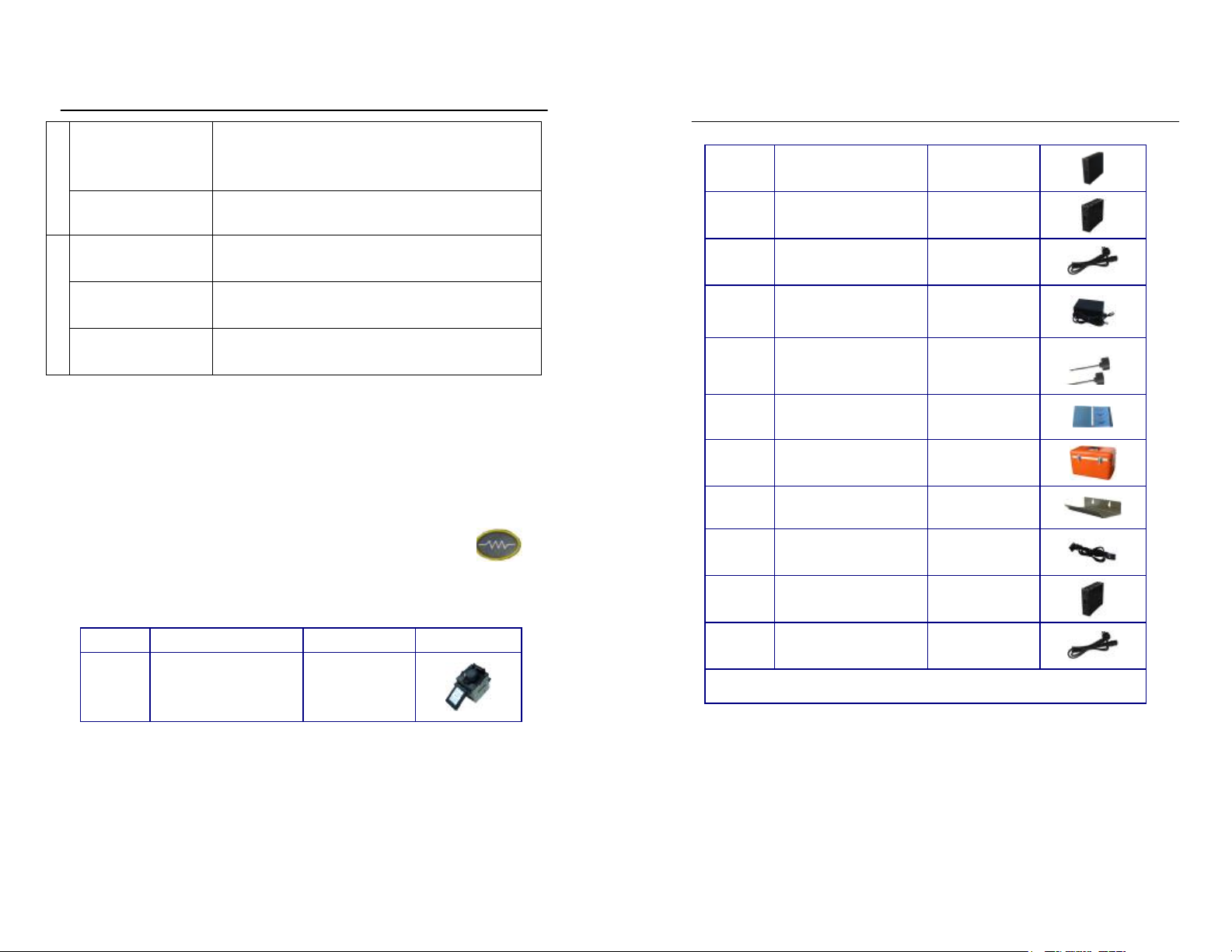
15.Useonlythe 85-264VAC,47-63Hz/12VDC,14Ah with WY-725.
.Theproper supply voltage source is85-264VAC,47-63Hz,Check theAC Power
sourcebeforeuse.Usingan improperAC powersourcemay causefuming,
electric shockorequipment damage andmay result in personal injury, death
orfire.
16.Use the suppliedACpower cord.Donotplace heavyobjects onthe
ACpower cord.Donotpull,heatup ormodifytheAC powercord. Use
ofanimproper cordor adamaged cordmaycausefuming,electricshock
orequipment damageand may resultinpersonal injury, deathorfire.
17.ConnecttheACpowercord properlytothesplicerandwallsocket.
When inserting theAC plug, make surethereisnodustordirt on
theterminals.Incomplete engagementmay causefuming, electric
shockor equipment damage and may result inpersonal Ijury,death
orfire.
18.The WY-725usesathree-prong(core) ACcordthat containsanearthed
groundsafetymechanism.Thesplicer MUST beGrounded/Earthed. Use
only the supplied three-prong(core)ACpowercord. NEVER usea
two-prong(core) power cord, extension cableorplug.
19.Use only theapproved batterypack with the WY-725. Only the
WY-725-01 batterypackcan be usedastheapprovedbatterypack.
20.Use the specifiedchargercord(WY-725-09) torecharge the battery
pack (WY-725-01).Usingother battery chargersandchargercords may
causefuming orequipmentdamageand resultin personalinjury,death
orfire.
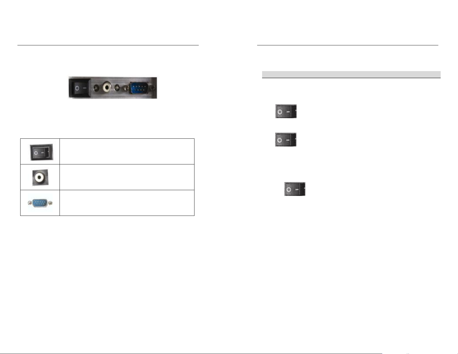
21.The splicerinletis used to disconnect thepowercordintheevent
ofafault. Besure topositionthesplicer sothatthe powercord
can be disconnected easily and quickly.
22.Disconnect theAC or DCpowercord fromthesplicer inletorthe
wall socket(outlet)immediatelyif the splicerortheexternal
battery emitsfumesor bad smell, or becomes noisyor hot.Leaving
theabnormalcondition unattendedwillcauseequipment
failure,electricshockorfireand mayresultinpersonal
injury,death orfire.
23. DisconnecttheAC orDC powercord fromthesplicerinletorthe
wall socket(outlet) ifthe splicer becomesdamaged(e.g., by
dropping).Leaving thesplicerin adamaged statemay cause equipment
failure,electricshockorfireand mayresultinpersonal
injury,death orfire.
24.DisconnecttheAC or DCpowercordfrom the splicerinlet orthe
wall socket(outlet)immediately if liquid(e.g.,water)or foreign
matter (e.g.,screw) enters the splicer. Leaving the splicer in a
damaged statemaycause equipmentfailure,electric shockor fire and
may result in personal injury,death or fire.
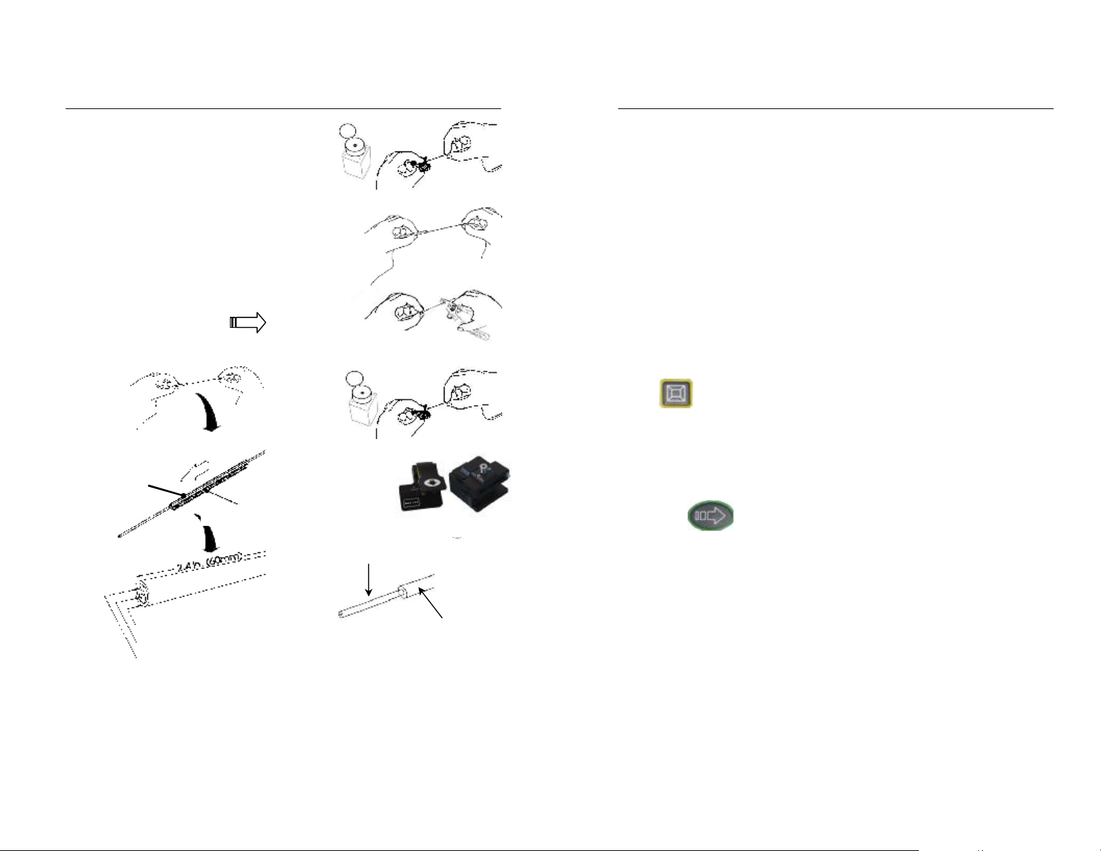
25.Cautionshould betakenwhenremoving the fiberprotectionsleeve
fromthetube heaterafterthe heatshrink cycleiscompleted.The
Page3 Page4

tube heater andfiberprotection sleeve arehot and should
not be touched.Possibleburn may result.
26.Replace the electrodes properly.
·Useonly specified electrodes.
·Setthe newelectrodes in the correct position.
·Replace theelectrodes as apair.
Disregard ofthe aboveinstructions maycauseabnormal arcdischargeand
result inequipmentdamageordegradation in splicing performance.
27.The equipmentmust berepaired or adjustedbyaqualified technician
orengineer. Incorrect repairsmay causefire or electric shock.
Shouldany problemarise,pleasecontactyour nearestsalesagency.
2.Description
2.1.Specification
ApplicableFiber
Singlemode andmultimode silicabased
opticalglassfiber
·Cladding diameter :100 –150um
·Coatingdiameter :0.1-1.0mm
1
Cleave LengthStandardspec :16mm
MeanSpliceLoss
(Note1)
·Singlemodefiber :Typ.0.02dB
·Dispersion shifted fiber :Typ.0.04dB
·Multimode fiber :Typ.0.01dB
MeanSpliceTime
(Note2) Typ. 8seconds
2
FiberProtection
Sleeve Shrinking
Time (Note 3)
40mm/60mm sleeve:Typ.40seconds
Dimensions170mm(W)/170mm(D)/145mm(H)
3
Weight 4.1 kg
4
Battery/Charger
WY-725-01withbatterychargefunction
·Inputpower :85~264V(47~63HZ)
·Outputpower:9~3V,10Ah
5
ProofTestForce ·Standard spec. :Approx.1.96N(200gf)
Page5 Page6

Program test
Atmospheric pressure(maximum altitude :5000m)、
temperature and humidity.Automaticcalibrationby
observingdistanceoftheGAPduringarc discharge
6
Wind ResistanceMaximum permissible wind velocity: 15m/s
Type of
Splice Mode AUTO,MANUAL
Programof
Splice Mode SM、MM、DS、NZDS、EDF
7
Storageof
Splice Results 8000 splice results in internal memory
Note 1:Mean splice loss:
Data based onsplicingsame-typefibers having an averagequality
according to the ITU-T standard.
Note 2:Mean splicingtime
·Lengthoftimefromthe startofoperation by pressingSTARTtill the
end of loss estimation.
Note 3:fiberprotection sleeve shrinking time
·Lengthof timefromthestart of heating bypressing <>till
the end of cooling.
2.2.Components
No. Name Model Fig.
(1)
Arc FusionSplicer
WY-725
(2)Li-Battery WY-725-01
(3)AC adaptor WY-725-02
(4)AC Power Cord WY-725-03
(5)Charger WY-725-04
(6)Spare Electrodes WY-725-05
(7)InstructionManual
WY-725-06
(8)CarryingCase WY-725-07
(9)Cooling salverWY-725-08
(10) Charger cordWY-725-09
(11)★
DC adapter WY-725-10
(12)★
DC Power Cord WY-725-11
Notes: ★optional
Page 8
Page7 Page8

2.3.Accessory for Operation
Fiber
Protection
Sleeve
Coat
Stripper
Fiber
Cleaving
Tool
Fiber
Cleaning
Tool
2.4.DescriptionandFunctionof Splicer
§2.4.1.MainBodyofSplicer:
WindProtector
TubeHeater
Handle
Powerswith
Fig.
2
-
3
SpliceMainEngine
Page9 Page 10
Lint-
freetissue
orGauze
ThinCotton
Swab
WY-105
Cleave Length:φ0.25:6-20mm
φ0.9:10-20mm
Fig.2-2OtherNecessaryItems
FiberProtectionSleeve
Fiber/PigtailCoatStripper
Dispenser
(Purity:morethan
99%
)
LCDMonitor
PanelKeyboard
Lock
RS232
Videooutput
Battery/DCadaptor/ACadaptor
OppositeAuto
Heat

§2.4.2.PanelKeyboard
(1)RightKeyboard
KeyName Function
Alternate
Manual: left/right,up/down
Menu 1.EnterMainMenu
2.ConfirmMenu
ExitExitMenu
Down 1.Menu:movecursordown
2.Manual:movefiberdown
Up 1.Menu:move cursor
2.Manual:movefiberup
Right 1.Menu: modifyparameter
2.Manual:movefiberright
Left 1.Menu: modifyparameter
2.Manual:movefiberleft
Fig.2-4RightKeyboard
Page 11 Page 12
KeyName Function
HeatStart/stoptube heater
StartStartsplice operation
ResetSplicerReset
Fig2-5Leftkeyboard

§2.4.3.PowerSupplySwitchandPlugs
PowerON/OFF
Videooutput
RS-232interface
3.Powerof Splicing Operation
STEP1:Connectthe splicer
Three supply:ACpower supply/internal battery/externalbattery.
(1)AC powersupply for fusionsplicer.
①PlugACadapter(WY-725-02),plug one endof ACpower cord
(WY-725-03) into AC adapter,an otherendintoAC power supply.
Press< >toturn on splicer;
(2)Internalbattery forsplicer
Plug internal battery(WY-725-01)intosplicer.
Press< >,turnonsplicer;
(3)Externalbattery forfusion splicer.
①Plug DC adapter into splicer.
②Plug one endofDCadapter(WY-725-12)into DCadapter,an other
end into external battery
③Press< >,Turn onsplicer;
STEP2:Fiberstripping
(l)Cleanthefiber outercoatingapprox. 100mminlengthfromthe
fiber endwithalcohol-impregnated lint-freetissueorgauze.
(2)Pass thefiberthroughthefiberprotectionsleeve.(Fig.3-1)
(3)Remove thefibercoating 30-40mmwith astrippingtool.
]Check:Afterthisoperation, handle the fiberso asnot todamage
its bare glass
Fig.2-6PowerSupplySwitchandPlugs
Page13 Page 14

(4)Clean the bare part With
anotheralcohol tissue.
]Check:Afterthisoperation,handle
the fibersoasnottodamage
its bare glass.
]Check:Use ahigh-quality
alcohol,greater than99%
pure.
]Check:Changelint-freetissue or
gauze eachtime
(5)Cleave the fiber with a fibercleaver,Refer to page21 §4.4.4
]Note:Cleavelength:16mm。
]Note:Donotcleanthe fiber aftercleaving.
STEP3:Setthefiberinthe splicer.
(l)Gently set thestrippedfiber in the V-groove.
]Check:Setthefiberend-facebetweenthe V-groovetipand
electrodecenterline.
(2)Gently close the sheath clamp.
(3)Close the windprotector.
STEP4:SelectSuitedSplicer Mode
Press< > intothesetupprogrammenu, SelectProgram ”be
selectedsuitedsplicer programof3column.Refer page 50§6.4
Select Program
STEP5:Splicingoperation
Press< > tostart splicing.Refer topage26§4.6
Splicing operation
STEP6:Fiber removal
(1)Open the wind protector
(2)Openthe leftandright sheath clamp ,Removethefiber.
Page 15
Fibe
PassFiber
TensionMember
Fiber protectionsleeve
Fig.3-1Pass Fiber
Full operation refer
rightFig.3-2
①CleanFiber
③Remove Coating
④CleanBareglass
⑤CleavingFiber
BareFiber
②Pass Fiber
Fiber protectionsleeve
Fiber melt sleeve
TensionMember
Coating
Fig.3-2 FiberStripping
Page 16

STEP7:Reinforce the splice.
(l)Slidethe fiberprotectionsleevetothe center ofthe splice
and moveit to the tube heater.
]Check:Make surethesplicepoint andfiberprotection sleeve
areinthe center of the tubeheater.
]Check:Make surethe reinforcing material is placed dow.
]Check:Makesurethe fiber isnot twisted.
(2)Whileapplyingtensionto thefiber,lowerthefiber into
thetube heater, thelefttubeheaterclampwillclose
automatically.
(3)Withtensionstill applied tofiber,closetheright tube
heater clamp with your left hand.
(4)Press< > tostarttube-heating cycle.
4.DetailofSplicing Operation
4.1.Preparationsbefore Splicing Operation
Prepare necessaryitems ,referringtopage7§2.3Other
Necessary Items forSplice Operation
4.2.Power Supply
Three supplying powertotheWY-725:ACPowersupply 、internal
battery、external battery .
aWarning:Followsafety instructions,refer tothe page1 to5
§1WarningsandCautionsforSafe Operation
4.2.1.Using AC Power supply
Tooperate the splicerfrom anACpowersupply176~264VAC,47~63Hz
(l)Confirmationbefore operation
aCheck:Make surethe powersourceis176~264VAC,47~63Hz.When
connecting to anACgenerator, always check the output voltage
of thegenerator withacircuittester before connecting the AC
power cord.
aCheck:Makesure theACpowercordis free from damage,etc.
(2)PlugAC adapterintosplicer.
(3)Plug theACpowercord(WY-725-03)intotheACadapterinlet ,
Makesure plugisfullyseatedandin the correctposition.
(4)Plugthe AC powercord into thewallsocket. Makesureplugisfully
seated and in the correct position.
(5)Press< >,turn onsplice.
Page 17 Page18

4.2.2.Using internal batterypack.
Power supply with internalbattery(WY-725-01).
(l)Plug internal battery (WY-725-01)into splicer.
aCheck:Check thebatteryifallright,Connectif preciseness.
(2)Press< >,turn on splicer.
4.2.3.Usingexternal battery.
①PlugDCadapter intosplicer.
②PlugDCCord(oneend)intoDCadapter ,another endintoexternal
battery
③Press< >,turnon splicer;
4.3.Turning On SplicerPower
aCheck:Toobtainagood splicingquality, perform the cleaning
andchecking proceduresbeforebeginning splicing
operation. Refer topage35.
§4.3.1.Power-On
Pressing< >turnson thepoweranddisplaysPower-On Menu
Page 19 Page20

1AUTO
MANUAL
M
MMMMM
§4.3.2. Ready Screen
①Currently selected mode
◇AUTO:[Working Mode]
Optional mode:
◇SM :[FiberType]
Optional mode:SM
MM
DS
NZDS
EDF
EXF
◇16:14:04 :[TIME]
②information
aNote:If change workingmodeorfibertype, Press< > setupmenu.
4.4.FiberStripping Operation
§4.4.1.Cleaning the Outer Coating
Cleanthefiber outercoatingapprox.100mmin lengthfromthefiber
end withalcohol-impregnatedgauze orlint-freetissue. Ifdust
orotherimpuritiesontheouter coating enter the fiber
protectionsleeve,burnoutorbreaking of fibermayresultafter
completion of installation.
§4.4.2.Passing through Fiber ProtectionSleeve
Pass onefiber through thefiber protection sleeve. RefertoFig.4-2
Fig.4-2 SettingFiber Protection Sleeve
Page22
Fiber
PassFiber
TensionMember
Sleeve
Fiberprotectionsleeve
Fibermeltsleeve
Tension Member
Page 21
①
º
②
º
1AutoSM08:20:19
1X1
―1PleasePlaceFiber ―
1Y1
MenuAuto
Fig.4-1 READYScreen

§4.4.3.Stripping and Cleaning
(1)Remove the fiber coating30-40mm witha stripping tool.
aCheck:Afterthisoperation, handle thefibersoasnot todamage
itsbare glass.
(2)Cleanthebare part ofthefiberwithanotheralcohol-impregnated
gauze or lint-freetissue.
aCheck:After thisoperation,handle thefiber soasnot todamage
itsbare glass.
aCheck:Use a highquality alcohol,greater than 99% pure.
aCheck:Changegauzeor lint-free tissue eachtime.
§4.4.4.FiberCleaving
aNote:Thecleave length is16mm
Notes: detailsteps ,Please refer to the fiber cleaver instruction
4.5.Setting Fiber in Splicer
(1)Open thewind protector.
(2)Open theleft and right sheath clamps.
(3)Placefiber in the V-groove.
aCheck:Make surethefiber isnot twisted whensettingitinto
the splicer.
aCheck:Ifthe fibercoatinghas curlmemory,or bend memory,Load
thefiberin suchamannerthat the crown(curve)ofthe
memory is turn upward.
aCheck:Care should betakentopreventdamage orcontamination
ofthe fiberend-face.Fiberend-facecontact onANYitem
includingV-groovebottommay resultin poor quality
splices.
Fig.4-3Setting Fibers I
(4)Gently closethe sheath clampwhile holding thefiber.
Page 23
Page24

aCheck:Observe fibersettingin theV-groove.Thefibershould
restin thebottomoftheV-groove,Reloadfiberif it
doesnot rest properly.
aCheck:Fiberend-faceshouldrestbetweenthe V-groovetip and
electrode centerline.Itis unnecessary thatthefiber
end-facebeexactly at the midpoint.
Fig.4-4Setting FibersII
(5)Repeat steps(3)and(4)for second fiber.
(6)Gently close the left and right fiberclamps.
(7)Close the wind protector.
4.6.Splicing Operation
The WY-725 usesimage processingtoidentify abnormalconditions
thatsometimesoccur duringthesplicingprocess.Asmallportion
of these defectssometimes goesundetectedand apoor quality
spliceoccurs.Visuallyinspectthefiber imageon the monitor to
confirmacceptance orrejection duringthevarious stageof the
splicing process.
(1)Startof splicing
Pressing< > moves the leftand rightfibersforward. After
completionofcleaning arc discharge,thefibersstopatthe
predetermined position.
aNote:Whenthe fiberaremovingforwardandtheyappeartohop up
and down,contaminationmaybepresentintheV-grooves or
the fibersurface,Cleanthe V-groovesandredofiber
preparation.
(2)Cleave anglemeasurement andalignmentoperation
Visuallyexaminetheconditionofthefiberend-face while the
splicer is in operation or at apause.
aCheck:Evenifnocleaveangleerroris displayed, press< >and
redo fiberpreparationifthefollowing cases occur.
Page 26
Crack Lip
Incline
Fig.4-5 State of Fiber End-face
Page 25
Left Fiber
Right Fiber
LeftSheath Clamp Right SheathClamp

When thethreshold ofcleave angleerrorisexceededanerror message
isdisplayed : LeftFiberEnd-facebadness ”or RightFiberEnd-face
badness”, Then redo cleave fiber.
Fig.4-10 调芯状态
Fig.4-10 State of alignfiber
aNote:Tochangethresholdofcleaveangleerror,refer topage
51§6.5perfect program
(3)Heatingwith arc discharge
After aligning the fibers,thesplicerwillproduceahighvoltage
arc dischargeto fusethe fiberstogether. Duringarc discharge,
observethefiberimageon the monitorscreen. Ifsomepartof the image
exhibits an extremely brightglow (hot spot),which is
createdbyburning contaminantslocatedonthe surfaceorend-face of
the glass, thereis apossibilityofthefibercore willbedeformed.
Althoughdeformationcan bedetectedbythe loss estimation function,a
re-splice is recommended.
Fig.4-11 Fibers Being Spliced
(4)Splice Inspection
Whenthespliced stateis abnormal,thesplicer displaysan
errormessage Splice Lost”.are-spliceisrecommended.
aNote:Best to programtest beforesplicing, selectanappropriate
state ,Avoidance appearthis phenomenon.Afresh splicertest
if appearthis phenomenon.
Page 27
LeftFiber
Left/Right fiber inciseEnd-face
A
Auto
O
SM
0
9
:
12
:
23
AlignFiber
1X
1Y
RightFiber
1Auto SM11 09:10:19 1
Arc
…
1X
1Y
Page28

Fig.4-8 Examplesofbad Splicing
aNote:Aslightlyfat spliceisnormal.Thereis no problemwith
the splice loss and reliability.
aNote:White line orblackline willappearonfiber’sjointwith
fluorineandtitanium,Becauseof optics,There’snoeffect
to joint.
(5)Spliceloss estimating
Theestimated splice lossis displayedon thescreen.
Fig.4-14 Result of Fiber Splicing
Insome casesthe splice losscanbe improved withthere-arc
feature.Press the < >.Afterre-arc discharge,Notdisplayedof
splice loss.
aNote:Thereare cases whenthe splice loss willdeteriorate after
re-arcdischarge.
Bubble
Flange
ThickBlack line
Shadow
WhiteLine
Faintness filament
Claddingoff
Core off
Dust
Page29
Fig.4-9 Examples of goodSplicing
Page 30
Estimatingvalue
º
Auto
SM
0
9
:
10
:
1
9
Loss 0.00dB
1X
1Y
Pleaseopenthecover
andtakeoutthefiber

(6)Storing splice resultPress< >or openthewind
protector andthe splicer
Willautomatically performtheproof testand storesthe splicing
result.InthememoryCMOSchipof thesplice result. WY-725canstorage
4000item splice result, Refer page 54§6.7.4 Splice register if
transfer thesplice result。
4.7.FiberRemoval
(1)Open the wind protector
aCheck:Heaterclampsshouldbe open,ready toreceivefiber and
splice protector sleeve.
(2)Openthe leftsheath clamp,holdingthe left fiberinyourhand.
(3)Opentherightsheathclamp,holdingthe right fiber inyour
hand.
(4)Remove the fiber fromthe splicer.
4.8.Reinforcingthe Splice
(l)Slidethefiberprotection sleevetothecenterofthesplice
and move ittothetubeheater.
aCheck:Make surethesplice point and fiber protection sleeve
are in thecenter ofthe tube heater.
aCheck:Makesurethereinforcingmaterial is placed downward.
aCheck:Make sure the fiber is not twisted.
(2)Whileapplying tensionto the fiber, lower thefiberintothe
tube heater. The leftheater clamp will closeautomatically.
(3)Tension fiber, closetheright heater clampwithyour left hand.
Fig.4-11 Setting in Tube Heater
aCheck:Checkagaintosee thatthe splicepointandfiber
protection sleeveare inthecenterofthe tube heater.
(4)Press< >tostart atube-heatingcycle.Uponcompletion
of heating, The heater LED turnsoff.
aNote:To abort the tube heatingcycle,press< >
(5)Open the leftandrightheaterclamps.Whileapplyingtension
to thefiber, gently remove thesplicereinforcement.
Page 31
Page 32
Center the splicepoint andthe sleeve
40mmSleeve
60mmSleeve

aNote:On occasions the fiberprotection sleevemay adherethebottom
ofthetube heater.Simplyuse acottonswaborsimilarsoft
tipobjecttogentlypushthefiberprotectionsleeve to
dislodge.
(6)Visuallycheck thesplice reinforcement forbubblesand impurities.
Shown in Fig.4-16,Three fordisqualificationneeded rework;
Twain foreligibility.
Fig.4-12 Possible result
4.9.Storing the fusionsplicer
Fusion splicerisan exact instrument. Its carrying caseWY-725-06
is especially design, With guarantee the fusion spliceernot
influence of bump、dust、hydrosphere.Put incarryingcase in time
of thefusion
splicer afterfusion.
aCheck:Cutoff the power before storing.
aCheck:Cleaning thecrucial partsin time:Pickupcamera、
Lamp-houselens、FiberpressandV-groove, Wipeoff the
dust anddunghill.
aCheck:Would theLCDsurveillancescreenvertical vail,
Entireness cling to thefusionsplicer
aCheck:Unchain the having line put in the carrying case.
aCheck:Liftthe fusionsplicer cased the carrying case.
aCheck:Casedtheotherfittings andexpendable, Lidandbutton
the carrying case.
aNote:Eliminate cleanlily theliquidinthebottle in time if
the alcohol bottlein thecarryingcase .Forfearspill
influence thefacility.
Page 33
P
<6mm
Bubbleonfiber
Bent of fiber
Uniform ofsleeve
Bubbleon cladding
Least 6mm
Page 34

5.MaintenanceofSplicing Quality
5.1Cleaning and CheckingbeforeSplicing
Critical cleaning pointsand maintenance checks aredescribed below.
5.1.1 Cleaning V-grooves
If contaminantsin theV-grooves, correctclamping maynot occur,
resultingin highersplice loss.TheV-grooves shouldbe frequently
inspected andperiodically cleaned during normal operation.
(l)Openthe wind protectorand fiberclamps.
(2)Cleanthe bottomoftheV-groove withanalcohol-impregnated
thin cottonswab asshown inFig.5- l. Remove excessalcohol
from theV-groove with aclean dry swab.
Fig.5-l. Cleaning V-grooves with CottonSwab
han99% pure.
]Check:Use carenot to contact theelectrode tips.
]Check:Donotuse excessiveforcewhencleaning theV-grooveThe
V-groovearmmaybe damaged.
(3)Ifthe contaminants in V-groove cannot beremoved withan
alcohol-impregnatedthincottonswab, useacleavedfiber end-face to
dislodgecontaminants from V-groove bottom. Repeat step(2)afterthis
procedure.
Fig.5-2Cleaning V-grooves with Cleaved Fiber
§5.1.2. CleaningFiberClamp Chips
Ifcontaminantsare present ontheclamp chips,correct
clamping maynotoccur,resultinginpoor quality splices. Thefiber
clampchipsshouldbe frequentlyinspectedandperiodically cleaned
V-grooves
Cotton Swab
Page 35
V-groove
CleavedFiber
Page 36
Table of contents
Popular Welding System manuals by other brands

Miller
Miller Trailblazer 302 Diesel owner's manual

ESAB
ESAB AristoMig 320 instruction manual

Mosa
Mosa DSP 2x400 PS-PL Use and maintenance manual

Lincoln Electric
Lincoln Electric INVERTEC POWER WAVE 450 SVM112-B Service manual

Hypertherm
Hypertherm POWERMAX 45 Field Service Bulletin

Miller
Miller XMT 350 MPa owner's manual