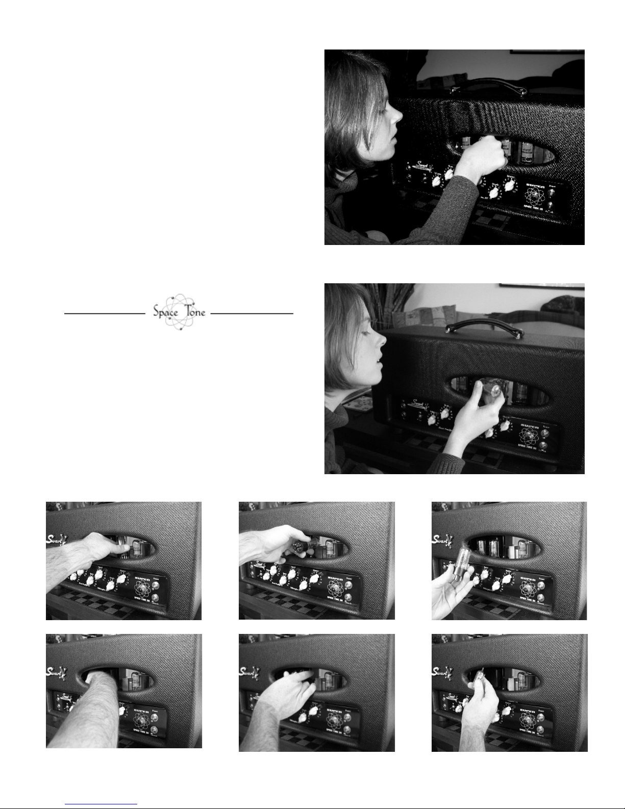
Once the panel is carefully removed, access to the
line of tubes is relatively easy, only involving
minimal Houdini-esque contortion. Interestingly,
shaping your hand into a virtual “pick grip” does
a good job in preparation for this duty.
See Audrey again at right, tube extraction
accomplished even with blinding flash going off
midway through move. True, it’s doubtful she’ll
ever do this again, but it’s not because it was all
that difficult.
Notice the mild look of disgust when eyeing that
6V6GT, this only because I had just said, “OK,
better put it back in.”
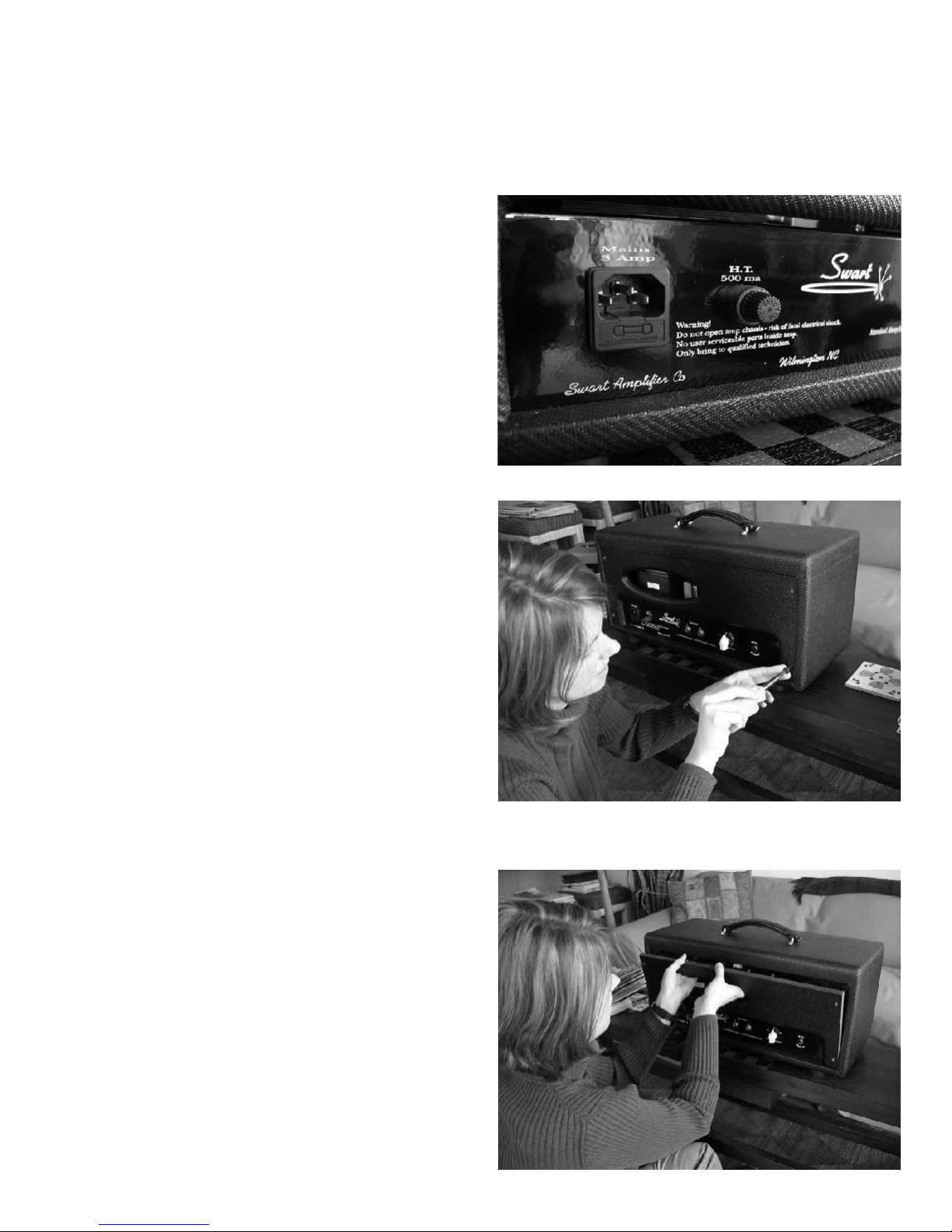
But many will be wondering if bypassing the rear
panel removal is at all possible. Swart seems to
prefer the panel option, but with my characteristic
laziness. I’m looking to the path of least resistance
solution..
Panel Removed
–
Clos
e Up view of Preamp tubes,
Output Trans, and Reverb tank output/input
Step 4: Witness Audrey carefully moving to
the tubes fr
om right to left for extraction.
Step
5
:
Now, Stare at tube.
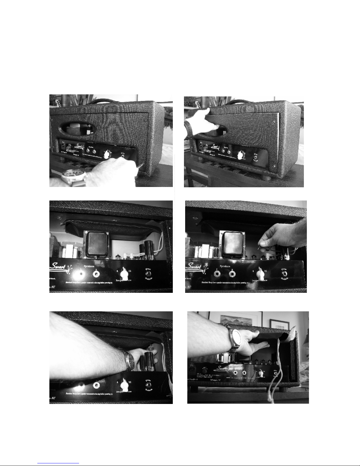
IMPORTANT REMINDER:
this goes for ALL tube components,
whether guitar or audio related -
Always, gently extract the tubes by
grabbing them at the base, carefully
easing them out with only subtle
movements back and forth, while
pulling straight up. If careful, you will
never hear that sickening snap of thy
tube pin or center key guide, a sound
that surely brings the deepest of groans
with horror sigh, closely followed by
the head in hands. Older sockets need
less movement to and fro, but new,
tight sockets will sometimes grip with
force. On the Super 30, you’ll notice
the guide keys for V5 thru V9 ALL
face at 2 o’clock if looking from the
rear (8 if replacing from front). This is
a big help when aligning the pins for
replacement. The preamp tubes have
the pin “C” opening facing 3 o’clock
from the rear, 9 from the front. Never
FORCE a tube into the socket. - kh