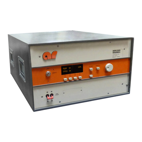
Amplifier Research 1000L User manual

160 School House Road, Souderton, PA 18964-9990 USA
Phone 215-723-8181•FAX 215-723-5688
MODEL 1000L
1200 WATTS CW
2500 WATTS PULSE
10kHz-220 MHz
The Model 1000L is an economical, self-contained, air-cooled broadband amplifier designed for
laboratory applications that require instantaneous bandwidth, high gain and high power output. Housed
in a stylish contemporary enclosure, the Model 1000L is smaller than competitive units with similar
power levels. All operating controls are functionally grouped on the front panel for simplicity of
operation. These include modern, lighted push-button switches for the command functions, POWER,
STANDBY, OPERATE and PULSE, a control for setting the output level of the amplifier, and a meter
for monitoring critical operating voltages and currents. Remote control is provided through a rear panel
mounted connector. Isolated TTL level remote control can be accomplished using our CP2001
interface. Isolated IEEE-488 compatible control can be provided with our CP3000. A highly versatile
unit, the Model 1000L features rugged circuitry and a quick-acting, solid state crowbar circuit to
protect the final amplifier tubes from damage due to internal arcing. An electronic circuit is provided
to enable rapid gating or blanking of the amplifier.
0
500
1000
1500
2000
2500
3000
3500
WATTS
1 10 100 1000
FREQUENCY (MHz)
1000L TYPICAL POWER OUTPUT
PULSE
CW
LINEAR @ 1dB COMPRESSION
0.10.010.001
REV060396
Advanced Test Equipment Rentals
www.atecorp.com 800-404-ATEC (2832)
®
E
s
t
a
b
l
i
s
h
e
d
1
9
8
1

SPECIFICATIONS
Model 1000L
POWER OUTPUT
High Range
Pulse
Minimum ..................................................................2500 watts to 150MHz
1750 watts to 220MHz
Duty Cycle ................................................................15%
Pulse Width...............................................................8 milliseconds
CW
Minimum ..................................................................1200 watts
Low Range .......................................................................100 watts nominal
FLATNESS, high range................................................... ±± 1.5 dB
FREQUENCY RESPONSE..............................................10 kHz - 220 MHz instantaneously
INPUT FOR RATED OUTPUT .......................................1.0 milliwatt maximum
GAIN (at maximum setting)
High Range.............................................................61 dB minimum
Low Range..............................................................47 dB minimum
GAIN ADJUSTMENT (continuous range).......................18 dB minimum
INPUT IMPEDANCE......................................................50 ohms, VSWR 1.5:1 maximum
OUTPUT IMPEDANCE...................................................50 ohms, nominal
MISMATCH TOLERANCE* ........................................... 100% of rated power without foldback. Will
operate without damage, or oscillation with any
magnitude and phase of source and load
impedance.
MODULATION CAPABILITY ........................................Linear amplitude and phase response to over 80 MHz
allows faithful reproduction of AM, FM, Pulse, or phase
modulation appearing on the input signal
HARMONIC DISTORTION AT 750 WATTS
Above 120 MHz.......................................................Minus 30 dBc maximum
Below 120 MHz.......................................................Minus 15 dBc maximum
Minus 18 dBc nominal
THIRD ORDER INTERCEPT POINT.............................66dBm Typical
GATING CHARACTERISTICS
Pulse Mode Pedestal/CW Mode Blanking
Signal (into 180 ohms)........................................Plus or minus 2.5 to 6.0 VDC
Rise time.............................................................20 microseconds maximum
Fall time............................................................. 4 microseconds maximum
RF Rise/Fall Time...................................................10 nanoseconds maximum
RF Pulse Droop ......................................................1.0% maximum at 8 milliseconds
PRIMARY POWER (specify one).....................................200/208 ±± 5% VAC, 3 phase, 50/60 Hz
380/415 ±± 5% VAC, 3 phase, 50/60 Hz
400/415 ±5% VAC, 3 phase, 50/60Hz
15.2 kVA nominal
CONNECTORS
RF Input.................................................................Type BNC female
RF Output, high range............................................Type C female
RF Output, low range..............................................Type N female
Gating/Blanking .....................................................Type BNC female
Remote Control .......................................................25 pin female subminiature D
COOLING........................................................................Forced air (self contained fans)
WEIGHT..........................................................................239 kg (525 lb)
SIZE (WxHxD) ................................................................56.1 x 149.9 x 58.4 cm
22.1 x 59.0 x 23.0 in
* See Application Note #27

Model 10WD1000 Manual Text
1-1
REV -
TABLE OF CONTENTS
SECTION I: GENERAL INFORMATION
1.1 General Description...................................................................1-1
1.2 Power Supplies.........................................................................1-1
1.3 Specifications............................................................................1-1
SECTION II: OPERATING INSTRUCTIONS
2.1 General............................................................................2-1
2.2 Amplifier Operation...........................................................2-2
2.2.1 Local Operation ........................................................................2-3
2.2.2 Remote Operation.....................................................................2-3
SECTION III: THEORY OF OPERATION
3.1 Introduction..............................................................................3-1
3.2 Frequency Discriminator............................................................3-1
3.3 DC to 0.5 MHz Amplifier ..........................................................3-2
3.4 0.5 to 1000MHz Amplifier.........................................................3-2
3.5 Power Supply ...........................................................................3-3
3.6 A4 Operate/Control Board .........................................................3-3
3.7 A5 Interface Board....................................................................3-3
SECTION IV: MAINTENANCE
4.1 General Maintenance Information...............................................4-1
4.2 Disassembly Procedures ....................................................4-1
4.3 Troubleshooting........................................................................4-2
4.3.1 Front Panel Vacuum Fluorescent Display (VFD) Doesn’t Indicate
“Power On”.............................................................................4-2
4.3.2 Unit Cannot be Operated Remotely.............................................4-3
4.3.3 Thermal Fault ...........................................................................4-3
4.3.4 Interlock Fault...........................................................................4-3
4.3.5 Voltage/Amplifier Faults.............................................................4-4
4.3.6 Low or No Power Output (DC Tests).........................................4-5
4.3.7 Low or No Power Output (RF Tests)..........................................4-6
4.4 Lo/No RF Output......................................................................4-7
4.5 Frequency Discriminator............................................................4-7
4.6 DC to 0.5MHz Amplifier Research.............................................4-7
SECTION V: REPLACEABLE PARTS
5.1 Introduction..............................................................................5-1
5.2 Ordering Information.................................................................5-1
5.3 Non-Listed Parts.......................................................................5-1
TABLE OF CONTENTS (CONTINUED)iii

Model 10WD1000 Manual Text
1-2
REV -
SECTION V: REPLACEABLE PARTS (CONTINUED)
5.4 Circuit Designators............................................................................................5-1
5.5 Manufacturers’ Abbreviation Listing...........................................5-2
5.6 Master List...............................................................................5-3
5.7 Schematics and Bills of Material (BOMs)....................................5-3
APPENDIX A: STANDARD ABBREVIATIONS FOR MANUFACTURERS..................A-1
SECTION VI: RECOMMENDED SPARE PARTS
6.1 Level of Maintenance................................................................6-1
WARRANTIES: LIMITATION OF LIABILITIES
LIST OF FIGURES
2-1 Model 10WD1000 Front Panel.................................................. 2-2
2-2 Model 10WD1000 Rear Panel................................................... 2-2
LIST OF TABLES
2-1 IEEE-488 Device Address Selection........................................... 2-5
2-2 Remote Error Codes/Messages.................................................. 2-6
2-3 RS-232 Connector Pin-Outs...................................................... 2-7

Model 10WD1000 Manual Text
1-1
REV -
SECTION I
GENERAL INFORMATION
1.1 GENERAL DESCRIPTION
The Amplifier Research (AR) Model 10WD1000 is a self-contained, broadband Radio Frequency (RF)
amplifier designed for laboratory applications where instantaneous bandwidth, high gain, and moderate
power output are required. Solid state technology is used exclusively to offer significant advantages in
reliability and cost. When used with a frequency-swept signal source, the AR Model 10WD1000 will
provide 10 watts of swept power output from DC–1000 megahertz (MHz). Typical applications include
antenna and component testing, wattmeter calibration, electromagnetic interference (EMI) susceptibility
testing, use as a driver for frequency multipliers and higher power amplifiers, and use as an RF energy
source for Magnetic Resonance Imaging (MRI) studies. The Model 10WD1000 can be operated locally by
using the unit’s front panel controls, or remotely by using its built-in IEEE-488 or RS-232 interfaces.
1.2 POWER SUPPLIES
The Model 10WD1000 contains two switching power supplies. The input voltage range to these power
supplies is 90–132 Volts Alternating Current (VAC) and 180–264 VAC, 50/60Hz, universal or automatically
selected. The user does not have to switch or change anything on the Model 10WD1000 when changing
the unit’s AC input voltage. The unit’s AC power consumption is 350 watts nominal. A built-in circuit
breaker provides primary AC circuit protection.
1.3 SPECIFICATIONS
Refer to the “Amplifier Research Data Sheet” on the following pages for detailed specifications.
All voltage measurements referenced in this manual are Direct Current (DC) unless stated otherwise.

Model 10WD1000 Manual Text
2-1
REV -
SECTION II
OPERATING INSTRUCTIONS
2.1 GENERAL
Operation of the Model 10WD1000 broadband RF amplifier is simple. The amplifier’s input signal, whether
swept or fixed in frequency, is fed into the jack labeled INPUT, and the amplifier’s output signal is taken
from the jack labeled RF OUTPUT. The unit is turned on by activating the POWER switch. A circuit
breaker in the AC power line provides protection in the event of a unit malfunction. A polarized, three-wire
AC power cord is also included with the unit to provide cabinet and chassis grounding to the power mains.
CAUTION:
OPERATION OF THE MODEL 10WD1000 BROADBAND RF AMPLIFIER IS NOT CRITICAL IN
REGARD TO SOURCE AND LOAD VOLTAGE STANDING-WAVE RATIO (VSWR), AND IT WILL
REMAIN UNCONDITIONALLY STABLE UNDER ANY MAGNITUDE AND PHASE CONDITIONS OF
SOURCE AND LOAD. IT HAS ALSO BEEN DESIGNED TO WITHSTAND INPUT POWER LEVELS UP
TO TWENTY (20) TIMES ITS RATED INPUT OF 1MW WITHOUT SUSTAINING DAMAGE.
HOWEVER, SIGNAL LEVELS >>20MW OR TRANSIENTS WITH HIGH PEAK VOLTAGES CAN
DAMAGE THE AMPLIFIER. ALSO, ACCIDENTAL CONNECTION OF THE AMPLIFIER’S OUTPUT
TO ITS INPUT CAN CAUSE OSCILLATIONS THAT WILL PERMANENTLY DAMAGE ITS INPUT
CIRCUITRY.
NOTE:
ALTHOUGH THE MODEL 10WD1000 HAS BEEN DESIGNED FOR THE OVERDRIVE AND LOAD
TOLERANCE CONDITIONS DESCRIBED ABOVE, SUBJECTING THE AMPLIFIER TO THESE
CONDITIONS SIMULTANEOUSLY CAN CAUSE FAILURE OF THE UNIT’S OUTPUT TRANSISTORS.
REPEATED FAILURES OF THIS NATURE WILL NOT BE COVERED UNDER THE UNIT’S
WARRANTY.
The Model 10WD1000 DC to 0.5 MHz Amplifier is protected from input overdrive by a diode limiter on
the RF input.
The 0.5 to 1000 MHz Amplifier is protected from input overdrive by limiting diodes across the RF input and
an Automatic Level Control (ALC) circuit that will limit the maximum RF level to the first gain stage (U1) of
the RF amplifier to approximately 0dBm.
The Model 10WD1000 power transistors are protected from over-temperature by a sensor that senses the
heat sink temperature near the RF output transistors. In the event of a cooling fan failure or an air flow
blockage, the DC voltage will be removed from the RF stages; if and when the heat sink temperature
reaches approximately 70°C, the unit’s front panel vacuum fluorescent display (VFD) will read
THERMAL FAULT. Normal operation can be resumed by resetting the Model 10WD1000 after the heat
sink temperature drops below 70°C.

Model 10WD1000 Manual Text
2-2
REV -
2.2 AMPLIFIER OPERATION
Figure 2-1 shows the front panel of the Model 10WD1000 broadband RF amplifier.
RF INPUT POWER 0-0.5
AUTO REMOTE
0.5-1000
RESET
FAULT
VOLTAGE
HAZARDOUS
RF OUTPUT
1-1000MHz
10 Watts
Model10WD1000
Figure 2-1
Model 10WD1000 Front Panel
Figure 2-2 shows the rear panel of the Model 10WD1000 broadband RF amplifier.
REFER SERVICING TO QUALIFIED PERSONNELOUTPUT
VOLTAGE
HAZARDOUS
F1 F2 F3
F1-6A, F2, F3-1.5A, 250V
600 WATTS
INTERLOCK
SAFETY IEEE-488 ADDRESS
6 1
RS-232
0
1
180-264V~
47-63Hz
90-132V~
LINE
RF NO OPERATOR SERVICEABLE PARTS INSIDE INPUT
MAINOPOWER
0
N
OF
F
1
RF
Figure 2-2
Model 10WD1000 Rear Panel

Model 10WD1000 Manual Text
2-3
REV -
2.2 AMPLIFIER OPERATION (CONTINUED)
2.2.1 Local Operation
Power-up Sequence:
1. Connect the input signal to the unit’s RF INPUT connector. The input signal level should be
0dBm maximum.
2. Connect the load to the unit’s RF OUTPUT connector.
3. Set the Function Switch to the applicable position.
4. Check to see that the MAIN POWER switch (circuit breaker) on the unit’s rear panel is set to the 1
(“on”) position.
5. Press the POWER switch: the front panel vacuum fluorescent display (VFD) should read
POWER ON, STATUS OK when power is applied.
(NOTE: The amplifier changes state each time the POWER switch is depressed—if the unit is
on when the POWER switch is depressed, it will turn off; if the unit is off when the POWER
switch is depressed, it will turn on.)
6. In the event of a fault, press the FAULT/RESET switch; if the fault does not clear, refer to
subsection 4.3 (“Troubleshooting”) of this manual.
NOTE: For applications with very short RF pulses or signals which contain many frequency components it may
be necessary to select the correct frequency range either on the front panel or remotely.
2.2.2 Remote Operation
2.2.2.1 Introduction
This subsection describes remote operation of the Model 10WD1000 amplifier by utilizing either the
IEEE-488 parallel interface or the RS-232 serial interface and a controlling device, such as a bus
controller or a personal computer (PC).

Model 10WD1000 Manual Text
2-4
REV -
2.2.2.2 Selecting Remote Operation
The Model10WD1000 can be placed in the remote operation mode at any time by
switching the FUNCTION switch on the front panel to the REMOTE position. In this
mode, control is transferred to the selected remote interface and all front panel
controls are inoperative with the exception of the FUNCTION switch. The amplifier’s
initial state will be Power Off. The front panel VFD will indicateREMOTE until the
unit is returned to the local operation mode.
2.2.2.3 Interface Selection
The Model 10WD1000 can be controlled via either the IEEE-488 or RS-232 interface; which
interface is active is determined by the position of Switch 6 of the rear panel Dual In-Line Package
(DIP) switch located between the two interface connectors. If Switch 6 is in the “on” (1) position,
the RS-232 interface will be active; if Switch 6 is in the “off” (0) position, the IEEE-488 interface
will be active.
2.2.2.4 Interface Set-up
Switches 1–5 of the rear panel DIP switch are used to select either the RS-232 communication
(BAUD) rate or the IEEE-488 device address, depending upon which interface is active. (Note:
These switches are only read at device power-up. In order for changes made in these switch
settings to take place, AC power must be removed and then re-applied to the Model 10WD1000.)
2.2.2.4.1 RS-232 BAUD rate selection
The serial communication (BAUD) rate can be set to five different levels. Selections are made by
the positions of Switches 1–5 of the rear panel DIP switch. The following is a list of the available
BAUD rates and the corresponding DIP switch positions:
BAUD Rate Switch On (1)
1200 1 only
2400 2 only
9600 3 only
19,600 4 only
76,800 5 only
(Note: Any other combination of switch settings will result in a BAUD rate equal to 1200.)
2.2.2.4.2 IEEE-488 device address selection
The IEEE-488 device address can be set to any number between 1 and 30. This selection is made
by setting Switches 1–5 of the rear panel DIP switch to the binary equivalent of the number.
Table 2-1 illustrates this switch selection.

Model 10WD1000 Manual Text
2-5
REV -
2.2.2 Remote Operation (continued)
2.2.2.4.2 IEEE-488 device address selection (continued)
Table 2-1
IEEE-488 Device Address Selection
Device Address Switch 5 Switch 4 Switch 3 Switch 2 Switch 1
1off (0) off (0) off (0) off (0) on (1)
2off (0) off (0) off (0) on (1) off (0)
3off (0) off (0) off (0) on (1) on (1)
4off (0) off (0) on (1) off (0) off (0)
5off (0) off (0) on (1) off (0) on (1)
:
:
30 on (1) on (1) on (1) on (1) off (0)
2.2.2.5 Command Set Format
Each command is composed of one alpha character, up to four numeric parameters, and a
command termination character. The command termination character is the “line feed” command,
which is denoted and entered as <LF>. Commands are case-sensitive and must be entered in upper
case only in order to be recognized.
2.2.2.6 IEEE-488 Communications
For IEEE-488 communications, the “End or Identify” (EOI) control line may also be used for
command termination. When sending commands to the Model 10WD1000 via the IEEE-488 bus,
terminate each command with a <LF>, an EOI, or both. No characters are permitted after the
<LF> or EOI; the 10WD1000interprets characters following the <LF> or EOI as the start of the
next command. When an error condition is present at the Model 10WD1000, the
“Service Request” (SRQ) line is asserted; the operator can then perform a serial poll operation.
The Model 10WD1000 error code (in binary) is contained in the returned serial poll status byte
(STB). These error codes are defined in Table 2-2.

Model 10WD1000 Manual Text
2-6
REV -
2.2.2 Remote Operation (continued)
2.2.2.6 IEEE-488 Communications (continued)
Table 2-2
Remote Error Codes/Messages
IEEE-488 Serial Poll Model 25W1000B Error Condition RS-232
Response (STB) Error
(binary/decimal) Message
(01000001) 65 INTERLOCK FAULT E1
(01000010) 66 THERMAL FAULT E2
(01000011) 67 POSITIVE 20 VOLT FAULT E3
(01000100) 68 POSITIVE 60 VOLT FAULT E4
(01000101) 69 NEGATIVE 60 VOLT FAULT E5
2.2.2.7 RS-232 Communications
If the RS-232 interface is active, the Model 10WD1000 will test for a properly connected RS-232
interface when it is switched into the remote operation mode. In order for the Model 10WD1000 to
recognize an RS-232 connection, the “Data Carrier Detect” (DCD) line must be asserted. This line
is sampled continuously to determine if the RS-232 connection is broken; therefore, it must remain
asserted in order for the RS-232 interface to function. The “Clear To Send” (CTS) line is also used
to gate information from the Model 10WD1000. This line must be asserted in order to receive
information from the Model 10WD1000. The CTS line can be used as a “handshake” line to
inform the Model 10WD1000 when it is permissible to send information. If the CTS line is de-
asserted in the middle of a transmission, the character in the process of being transmitted will be
completed and further transmission will halt until the CTS line is re-asserted. The
Model 10WD1000 itself asserts two lines: “Data Terminal Ready” (DTR) and “Request To Send”
(RTS). The DTR line is continuously asserted, while the RTS line is used to gate information into
the Model 10WD1000. Connector pin-out information is given in Table 2-3.

Model 10WD1000 Manual Text
2-7
REV -
2.2.2 Remote Operation (continued)
2.2.2.7 RS-232 Communications (continued)
Table 2-3
RS-232 Connector Pin-Outs
Pin No. Signal Data Direction* Description
1 DCD <Device Carrier Detect
2 RD <Receive Data
3TD >Transmit Data
4DTR >Data Terminal Ready
5GND N/A Ground
6 NC N/A No Connection
7RTS >Ready To Send
8CTS <Clear To Send
9 NC N/A No Connection
*Note:
> = Output from Model 10WD1000
< = Input to Model 10WD1000
Special Note:A null modem cable or adapter is required in order to properly interface the
Model 25W1000B to a standard serial port on a computer.
Once the RS-232 interface is established, commands are processed in the same manner as that of
the IEEE-488 interface. The command structure is identical, except that there is no EOI line.
Therefore, all commands are terminated with a line feed (<LF>). Since this is a full-duplex
asynchronous interface, if the Model 10WD1000 detects an error, the error message is immediately
transmitted to the host controller. These error messages are defined in Table 2-2.
2.2.2.7.1 RS-232 port settings
The RS-232 port settings used for communication with the Model 25W1000B are as follows.
Word Length: 8 bits
Stop Bits: 1
Baud Rate: 1200–76,800 (switch-selectable)
Parity: None
2.2.2.8 Remote Commands
The following commands are available to the user for remote communication and operation of the
Model 10WD1000. In the descriptions of these commands, a lower-case “x” is used to signify a
numeric value or parameter.

Model 10WD1000 Manual Text
2-8
REV -
2.2.2 Remote Operation (continued)
2.2.2.8 Remote Commands (continued)
2.2.2.8.1 Power On/Off
Controls the power on/off state of the Model 10WD1000.
Syntax: Px
Parameters: 0 = power off
1 = power on
Example: To turn the power on, send the following command:
P1<LF>
2.2.2.8.2 Function
Selects frequency band or remote operation.
Syntax:Bx
Parameters: BA = Auto
BL = Lo Band
BH = Hi Band
:
:
Example: To set the Model 10WD1000 to Auto, send the following command:
GBA<LF>
2.2.2.8.3 Reset
Resets the Model 10W1000, clearing all faults, if possible.
Syntax: R
Parameters: None
Example: To clear a fault, send the following command:
R<LF>

Model 10WD1000 Manual Text
3-1
REV -
3.1 INTRODUCTION
The Model 10WD1000 Amplifier consists of a DC to 0.5MHz and a 0.5MHz to 1000MHz Amplifier and a
frequency discriminator on the heatsink, two power supplies and a operate/control circuit are located on the
bottom side of the unit.
The RF input signal is connected from the front panel of the 10WD1000 to the input of the Frequency
Discriminator. The correct frequency band can be selected automatically by the Frequency Discriminator or
selected manually from the front panel or remotely. The Frequency Discriminator also controls relay K3 on
the RF output to select either the DC-0.5MHz or the 0.5-1000MHz band.
The DC-1MHz amplifier consists of low level opamps, complimentary drivers, the output stages, the input
signal limiter and an output protection circuit. The overall gain is typically 40dB.
The 1-1000MHz amplifier consists of four stages of low level gain, and a two stage output amplifier The
overall amplifier gain is typically 40dB.
The Frequency Discriminator consists of one active low pass filter and amplifier, a high pass filter and
amplifier, detectors and a comparator. The output is used to control RF relays on the input and the output
of the 10WD1000.
The Power supply consists of a ±12V. +5V supply (PS1) a ±60 volt supply, at 1.5 amps and 20V at 10
amps (PS1) and associated relays, fuses and line filters. The operate/control board is also in the Power
supply.
3.2 FREQUENCY DISCRIMINATOR
The RF input connector on the front panel of the 10WD1000 is connected to J1 of the Frequency
Discriminator. A sample of the RF input is fed to a low pass filter and a high pass filter. The low pass filter
has a 3dB point of approximately 1MHz. Integrated circuit U1A, C4, C5, R3, R4 and R5 form an active
low pass filter. I.C. U1B amplifies the signal from U1A and drives a detector CR1 and a phase inverter U2A
which drives detector diode CR2. The outputs from the low band detector diodes are sensed across R20 on
the inverting input of comparator U3A.
Capacitors C10, C11 and inductor L1 form a high pass filter with a 3dB point of approximately 1MHz. I.C.
U4 is a monolithic RF amplifier with approximately 25dB gain to over 1000MHz.
The output from detector diode CR3 is sensed across R22 at the non-inverting input of comparator U3A.
Diodes CR4, CR5 CR7 and CR8 along with the resistors in series with them help to lower the maximum
voltage developed across the input of the comparator during large signal conditions, for improved
comparator operation.
The output of the comparator U3A drives Q5 which drives Relay K1, on the frequency discriminator to
select either the Low band or the High band amplifier. Q5 also drives K3 to connect either the high or low
band amplifier to the RF output connector of the front panel.
I.C. U5A and U5B are one shot multi-vibrators which turn off the RF for approximately 20msec. during the
time the RF relays are switching, by switching the monolithic switch U6 to the terminated (off) position.
Voltage regulators U7 and U8 supply regulated ±15 VDC to the frequency discriminator board.
3.3 DC to 0.5MHz AMPLIFIER OPERATION

Model 10WD1000 Manual Text
3-2
REV -
The DC to 0.5MHz module is a direct coupled amplifier capable of 10 watts saturated power. The amplifier
operated class B with a quiescent current of approximately 150ma. Current feedback is used to provide
wide amplifier bandwidth. Positive and negative 60 volt power supplies allow for direct coupling throughout
the amplifier. The power supplies are current limited to approximately 1.7 amps to protect the amplifier
from input overdrive and short circuits on the amplifier output.
The input signal is fed to a Diode Bridge type of limiter. This circuit begins to limit at an input signal of
approximately 0dBm, to protect the amplifier from input overdrive. The signal is then fed to the first stage
U1. This stage is a preamplifier with a voltage gain of approximately 15dB. The amplified signal is then fed
to the second stage (U2, Q1 and Q2). This stage provides the level shifting to the high voltage levels
required. Q1 and Q2 supply the drive to the third stage (Q3 and Q4) which supplies a majority of the
voltage gain and sets up the quiescent current thru diodes CR1, CR2 and CR3. Transistor Q5 with Q9 and
Q6 with Q10 are compound source followers, which supply the power gain of the circuit. Zener diodes VR5
and VR6 protect the gates of the MOSFET output transistors against overvoltage. Transistors Q7 and Q8
with their associated circuitry provide fast overcurrent protection by limiting the drive signal to the output
stages.
3.4 0.5-1000MHz RF AMPLIFIER OPERATION
The RF Low Level stage is schematic number 1010543.
The RF input signal is fed to the first gain stage U1 thru the input attenuator, diodes CR1, CR2 and CR3.
Diodes CR4 and CR5 are the RF input limiter diodes. The output of U1 is fed to gain stage U2 and the
detector diode CR6 thru a fixed RF attenuator R27, R28 and R40. Diode CR6 detects the RF output level
of U1.
The detected signal is fed to U3A which amplifies the detected signal. The output of U3A is fed to U3B
which is used as a voltage comparator. The output of the voltage comparator is fed to the variable RF input
attenuator. When the RF input level to U1 reaches approximately 0dBm the current thru the series diodes
CR2 and CR3 decreases maintaining the RF level to U1 at approximately 0dBm. This helps to protect the
RF stage from damage which could result from RF overdrive on the input.
Integrated circuit U2 further amplifiers the RF signal from U1 and provides RF input to Q4 which amplifies
the RF signal and provides RF input to Q3. The output of Q3 is fed to gain equalizer (C10, R22, R23, L9,
R24) which helps to reduce the low frequency gain. The output of the gain equalizer is fed to the first driver
stage. Transistor Q1 and Q2 are used to maintain the collector current thru RF stages Q4 and Q3 at a
constant value.
3.4 0.5-1000MHz RF AMPLIFIER OPERATION (Continued)
The output stage, Schematic Number 1006556, consists of push-pull RF stages Q3 and Q4. T4 is a phase
splitter which provides signals of the correct phase to the base of Q3. T1 is a matching transformer between
the output of Q3 and the input of Q4. Resistor/capacitor network C14, R14 and R15, C29, R25 and R26
help to reduce the excess low frequency gain of the amplifier. Transformer T2 and T3 match the collector
of Q4 to 50 ohms. Transistors Q1, Q2, Q5 and Q6 sense the collector current of Q3 and Q4 and help to

Model 10WD1000 Manual Text
3-3
REV -
maintain constant collector currents. Q3 is set to 0.9 amps per side, Q4 is set to 1.5 amps per side. The
output of Q4 is fed to RF relay K3 which is connected to the RF output connectors on the front panel.
The RF amplifier stages A4, A5, A6 and A7, Schematic Number 1006773 are push-pull gain stages
.Transformer T1 is a phase splitter providing signals of the correct phase to the inputs of Q2. Transformer
T2 and T3 match the collectors of Q2 to 50 ohms. Transistors Q1 and Q3 sense and regulate the collector
currents of Q2 at 1.5 amps per side.
3.5 POWER SUPPLY ASSEMBLY (SCHEMATIC DIAGRAM NO. 1009777)
The Power Supply Assembly consists of two switching power supplies: PS1 and PS2. PS1 is a 25-watt,
triple-output power supply with three regulated outputs: +5V, +12V, and -12V. PS1 has a universal input
range of 85–264VAC, 50/60Hz. PS1 supplies +12V to supply power to the Operate/Control Board and to
operate relay K1, which switches the AC input power to PS2 for both local and remote operation. PS1 also
supplies +5V and -12V to power the Operate/Control Board. PS2 is a 20V, 10A, +60V, 1A supply with a
Power Factor Corrected front end; it will operate over an input voltage range of 85–264VAC, 50/60Hz.
PS2 supplies +20V, which is fused through fuse F1 and +60V which are fused through F2 and F3. The
outputs of these fuses supply DC power to all of the RF Amplifier gain stages. PS2 also supplies +20V to
operate Blower B1, which supplies air flow to cool the heat sink and the power supplies.
3.6 A4 Operate/Control Board (Schematic Diagram No. 1008597)
The A4 Operate/Control Board is a microcontroller-based printed wiring board (PWB) assembly that allows
sensing and control of internal signals as well as remote personal computer (PC) control via on-board RS-
232 and IEEE-488 data communications ports. The A4 Operate/Control Board utilizes a state-of-the-art,
Reduced Instruction Set Computing (RISC) microcontroller that can quickly and reliably perform all front
panel control and monitoring tasks, thereby allowing real-time control of the Model 25W1000B via either
remote bus. Besides being reported remotely, all amplifier faults are continuously monitored and indicated
via the unit’s front panel VFD.
3.7 Interface Board (Schematic Diagram No. 1009951)
The A5 Interface Board is composed of resistive networks and an I.C. switch.
The resistive networks condition the various voltage levels for use by the operate/control board. The I.C.
switch U1 decodes the outputs of the operate/control board to provide the band switching signals.

Model 10WD1000 Manual Text
4-1
REV -
SECTION IV
MAINTENANCE
4.1 General Maintenance Information
The Model 10WD1000 is a relatively simple instrument that should require very little maintenance. It is
built with printed wiring boards (PWBs) and solid state components in order to ensure long, trouble-free life.
However, should a malfunction occur, special care must be taken when servicing the unit in order to avoid
damaging the solid state components or the PWBs.
Since the unit’s solid state components are soldered in place, substitution of components should not be
resorted to unless there is some indication that they are faulty. In addition, care must be taken when
troubleshooting to avoid shorting amplifier voltages. Small bias changes may cause excessive dissipation or
transients that could ruin the amplifier.
All components utilized in Amplifier Research instruments are conservatively operated to ensure maximum
instrument reliability. Despite this, parts within an instrument may fail. In most cases, the instrument may
be repaired immediately with a minimum of “down time.” A systematic approach to troubleshooting can
greatly simplify and thereby speed up the required repairs.
However, due to the critical importance of maintaining the amplifier’s alignment, it is recommended that the
unit be returned to the factory for part replacement and amplifier realignment whenever failure is caused by
a breakdown of any of the components in the amplifier’s RF signal circuits. Shipping instructions are as
follows.
Please ship the unit PREPAID via United Parcel Service (UPS) to:
Amplifier Research Corporation
160 School House Road
Souderton, PA 18964-9990 USA
4.2 Disassembly Procedures
CAUTION:
EXTREME CAUTION SHOULD BE UTILIZED WHEN TROUBLESHOOTING THIS UNIT,
PARTICULARLY WHEN MEASURING VOLTAGES IN THE POWER SUPPLY SECTION, SINCE
HAZARDOUS VOLTAGES EXIST IN THE UNIT THAT COULD CAUSE SERIOUS INJURY TO ANY
PERSONNEL PERFORMING THE MEASUREMENTS.
The amplifier can be removed from its housing by removing four (4) screws from the front panel and four
(4) screws from the back panel. The amplifier can then be slid from its housing. The top cover can be
removed to gain access to the RF assemblies; the bottom cover can be removed to gain access to the power
supplies.

Model 10WD1000 Manual Text
4-2
REV -
4.3 Troubleshooting
Troubleshooting the Model 10WD1000 in a logical manner can speed the solution to a problem. The
settings of potentiometers (“pots”), capacitors (“caps”), or other variables should not be disturbed until other
problems have been eliminated. Comparing the measured DC voltages to those shown on the schematics
can solve many problems. Before measuring circuit voltages, first verify that the voltages to the circuits are
correct.
Model 10WD1000 Troubleshooting Categories:
Subsection 4.3.1—Front Panel Vacuum Fluorescent Display (VFD) Doesn’t Indicate “Power On” when
the POWER Switch is Depressed
Subsection 4.3.2—The Unit Cannot be Operated Remotely
Subsection 4.3.3—Thermal Fault
Subsection 4.3.4—Interlock Fault
Subsection 4.3.5—Voltage Faults
Subsection 4.3.6—Low or No Power Output (DC Tests)
Subsection 4.3.7—Low or No Power Output (RF Tests)
4.3.1 Front Panel Vacuum Fluorescent Display (VFD) Doesn’t Indicate “PowerOn” when the
POWER Switch is Depressed (Schematic Diagram No. 1009777)
4.3.1.1 If the Model 10WD1000 is operating in an otherwise normal fashion, the unit’s front panel
vacuum fluorescent display (VFD) or the wiring to it could be defective.
4.3.1.2 Check the FUNCTION switch on the unit’s front panel; it must be set to the LOCAL
position in order to operate the front panel POWER switch. Check the circuit breaker on the
unit’s rear panel; it must be set to the “1” (“ON”) position.
4.3.1.3 If the “Power On” indication is not displayed and the cooling fan (Blower B1) is not
running, check to see that the unit is plugged into a live outlet and that the AC line cord is
plugged securely into the unit.
4.3.1.4 Check the output voltages from PS1; these voltages should be as follows:
PS1 J2, Pin 1 +12.0 ± 0.3VDC
PS1 J2, Pin 2 + 5.0 ± 0.2VDC
PS1 J2, Pin 6 -12.0 ± 0.3VDC
If output voltages are not present on PS1, check the AC input to PS1.
4.3.1.5 Check the voltages to the A4 Operate/Control Board on connector A4 J2; the voltages
should be as follows:
A4 J1, Pin 16 -12.0 ±0.3VDC
A4 J1, Pin 29 + 5.0 ±0.2VDC
A4 J1, Pin 31 +12.0 ±0.3VDC

Model 10WD1000 Manual Text
4-3
REV -
4.3 Troubleshooting (continued)
4.3.1 Front Panel Vacuum Fluorescent Display (VFD) Doesn’t Indicate “PowerOn” when the
POWER Switch is Depressed (Schematic Diagram No. 1009777) (continued)
4.3.1.6 Check the voltage on A4 J1, Pin 6; it should be ≥4V when the POWER switch (S3) is in
the normal position and <0.1V when S3 is depressed. S3 is normally open; it is closed only
when it is depressed. The amplifier should change state every time the POWER switch is
depressed.
4.3.1.7 If all voltages are correct and the unit still does not operate, contact Amplifier Research to
arrange for repair or replacement of the A4 Operate/Control Board.
4.3.2 The Unit Cannot be Operated Remotely
4.3.2.1 Verify that the front panel FUNCTION switch is set to the REMOTE position.
4.3.2.2 Verify that the unit operates locally by resetting the FUNCTION switch to the LOCAL
position; if the unit does not operate locally, see subsection 4.3.1 of this manual.
4.3.2.3 Check the position of the “ADDRESS” switch assembly (SW1) on the A4 Operate/Control
Board; this assembly can be accessed through the unit’s rear panel. Check to see that these
switches are properly set for either RS-232 or IEEE-488 operation, as desired.
(See subsection 2.2.2 of this manual for the proper “ADDRESS” switch settings.)
(Note: Address switches are only read at unit power-up; remove and re-apply AC power (i.e.,
reset the circuit breaker) after changes are made.)
4.3.3 Thermal Fault (Schematic Diagram No 1009777)
During a Thermal Fault, the front panel VFD should read “THERMAL FAULT.”
4.3.3.1 Try to reset the unit; if the unit resets and operates normally, check to see that the cooling
fan (B1) is operating normally and that the air inlet on the bottom of the unit and the air outlets
on the rear of the unit are not blocked.
4.3.3.2 If the unit does not reset and the cooling fan is operating normally, check the voltage at the
A4 Operate/Control Board, J1, Pin 43; it should be ≤0.1V.
4.3.3.3 If the voltage on A4 J1, Pin 43 is high, check the thermal daisy chain through S2 and S1 to
ground.
4.3.4 Interlock Fault (Schematic Diagram No. 1009777)
The Model 10WD1000 is equipped with an interlock connector, which is located on the rear panel. The
interlock circuit can be used to sense the openings of doors to screen rooms, test chambers, and so forth,
and to turn off RF energy when these doors are opened.

Model 10WD1000 Manual Text
4-4
REV -
4.3 Troubleshooting (continued)
4.3.4 Interlock Fault (Schematic Diagram No. 1009777) (continued)
Note: The Model 10WD1000 is shipped with a mating connector, which has a jumper between Pins
1 and 8, installed in the rear panel interlock connector. The unit will not operate unless the
interlock circuit is closed.
4.3.4.1 In the event of an Interlock Fault, the unit’s front panel VFD should indicate
“INTERLOCK FAULT.”
4.3.4.2 Check to see if it is safe to power up the unit—are there personnel present in the screen
room, or are doors to the screen room open?
4.3.4.3 After checking for safety, try to clear the Interlock Fault from the front panel by using the
RESET switch.
4.3.4.4 If the Interlock Fault will not clear, check for continuity in the External Interlock Circuit
(Pin 1 to Pin 8 in the connector, which mates with J2 in the rear panel).
4.3.4.5 Check the voltage on A5 J1, Pin 11; it should be ≥4.0V.
4.3.4.6 Check the voltage on A4 J1, Pin 44; it should be ≥4.0V.
4.3.4.7 If all of the above voltages are correct and the unit still will not reset, check for defective
wiring and/or PWB connections, then try the RESET switch again. If the unit still will not
reset, the A4 Operate/Control Board is defective. Contact Amplifier Research to arrange for
repair or replacement of the A4 Operate/Control Board.
4.3.5 Voltage/Amplifier Faults (Schematic Diagram Nos. 1009777)
The Model 10WD1000 fault circuits sense a +20V fused fault and +60 fused faults. The fuse fault
circuits are located on the A5 Interface Board.
Fuse faults: Fuse faults are sensed by voltage dividers located on the A5 Interface Board; the outputs of
the voltage dividers are then fed to the A4 Operate/Control Board via the following pins on A4J1:
Pin 40—Fuse F1
Pin 41—Fuse F2
Pin 42—Fuse F3
The output voltage should normally be +5.0VDC.
This manual suits for next models
1
Table of contents
Other Amplifier Research Amplifier manuals

Amplifier Research
Amplifier Research 10W1000 Service manual

Amplifier Research
Amplifier Research 500A100A User manual

Amplifier Research
Amplifier Research 200T4G18 Service manual

Amplifier Research
Amplifier Research Amplifier Research User manual

Amplifier Research
Amplifier Research 100A250 series User manual

Amplifier Research
Amplifier Research 75A250A User manual