SYRIUS TS-INOX STT User manual

VERSION 07.22
INSTALLATION GUIDE
Solar water heater Thermosiphon INOX
TS-INOX STTFlat Roof - Systems TS-202INOX, TS-304INOXS–INOX
Thermosiphon Solar Water Heater

Page 2of 20 V07.22
Welcome
Thank you for choosing our thermosiphon solar water heater from the TS-INOX range. The TS-INOX system is a
high quality product. The solar energy is transmitted through by an absorber with a highly selective coating. The
robustness of the system is ensured by the tempered safety glass pane, the enameling of the hot water tank and
the Magnelis® steel of the supports.
System
TS-202INOX
TS-304INOX
Type of system
Thermosiphon, direct circulation, without heat exchanger
Net volume
195 l
279 l
Weight empty
104 kg
150 kg
Weight of full system
299 kg
429 kg
Roof installation
Flat roof
Collectors
1x C2000 D12c
2x C2000 D12c
Type
Flat plate collector
Gross surface area
2.06 m²
4.12 m²
Type of absorber
Absorber made of selective aluminum laser welded on Cu tubes
with 8 harp tubes Ø12mm and two manifolds Ø22mm
Absorber coating
Highly selective coating (absorptance 95%, emittance 5%)
Dimensions
2033 x 1015 x 98 mm
2033 x 2076 x 98 mm
Net weight
31 kg
62 kg
Liquid content
2.13 l
4.26 l
Cover
Tempered structural glass, 3.2mm, transmission 91%.
Stagnation temperature
180°C
Tank
BHX200
BHX300
Tank type
Stainless steel 316L
Dimensions
1480 mm, Ø 550 mm
1975 mm, Ø 550 mm
Net weight
44 kg
55 kg
Heat transfer
Direct circuit, without heat exchanger
Insulation
50mm PU
Max. pressure
10 bar
Corrosion protection
INOX 316L
Cold Water inlet
¾” M
Hot Water outlet
¾” M
Hydraulic kit
Solar circuit fluid
Water
Water
Tube
Copper pipe, Ø 18mm
Copper pipe, Ø 18mm
Pipe mass
1,6 kg
1,8 kg
Max. pressure
10 bar
10 bar
Support
Material
Magnelis steel
Magnelis steel
Mass
29 kg
33 kg
Permissible load
Max. snow load (pressure) 3 kN/m², Max. wind speed 245 km/h
No
TS–INOX Thermosiphon Solar Water heater

V07.22 Page 3of 20
Nomenclature
N°.
Description
TS-202INOX
TS-304INOX
1
BHX200 tank, net volume 195 l
1
2
BHX300 tank, net volume 279 l
1
3
C2000 D12c, collector, harp 2x manifolds Ø22 mm,
8x tubes Ø12 mm
1
2
4
Basic support -STT TS
1
1
4.1
Right spar TS
1
1
4.2
Lefts spar TS
1
1
4.3
Collector crossarm TS 202
2
4.4
Collector crossarm TS 304
2
4.5
Tank crossarm TS 202
2
4.6
Tank crossarm TS 304
2
4.7
Right sole TS
1
1
4.8
Left sole TS
1
1
4.9
Rear foot TS
2
2
4.10
Brace TS
2
2
4.11
TS Cross-brace
2
2
5
Basic support, Screws
1
1
5.1
Hexagon head screw M8x16
39
45
5.2
M8 nut
29
29
5.3
Flat washer M8
39
45
5.4
Grower washer M8
29
29
5.5
Anchor bolt M8
4
4
6
Hydraulics
1
1
6.1
Hydraulic tube infeed
1
1
6.2
Hydraulic return pipe (with insulation)
1
1
6.3
Elbowed brass compression fitting 22x18
1
2
6.4
Elbowed compression brass fitting F3/4''x18
2
2
6.5
Straight brass compression fitting 22x18
1
6.6
Straight brass compression fitting 22x22
2
6.7
Compression brass plug 22
2
2
6.8
Brass free nut 18x3/4".
2
6.9
3/4'' HT fibre gasket
2
4
6.10
Safety group
1
1
7
Optional
7.1
Thermostatic mixer
1
1
7.2
Pressure balancing valve
1
1
7.3
Electric backup
1
1

Page 4of 20 V07.22
Hydraulic diagram
Systems dimensions
TS-202INOX
STT
TS-304INOX
STT
1570 mm 2270 mm
DHW Tank
Collector Solar
Solar
outlet
Solar
inlet
Safety group
CW inlet
DHW output
Thermostatic
mixer
Valves
Pressure
reducing valve
Filter
DHW
Power supply
CW
1540 mm for 25°
2300 mm
1200 mm for 15°
2300 mm

V07.22 Page 5of 20
Performance
The performance of TS-INOX water heaters has been determined by the Institute for Building
Energetics, Thermotechnology and Energy Storage (IGTE) at the University of Stuttgart in Germany
according to EN 12976-2:2006.
The following table summarises the annual performance of TS-INOX, according to location.
Qd: heat demand in MJ/a, QL: solar energy yield in MJ/a, f-sol: solar fraction
TS-202INOX
Qd
QL
f-sol
Qd
QL
f-sol
Qd
QL
f-sol
MJ/a
MJ/a
%
MJ/a
MJ/a
%
MJ/a
MJ/a
%
litres/day
80
110
140
Stockholm
4441
2509
56.5
6107
3120
51.1
7772
3590
46.2
Würzburg
4257
2549
59.9
5854
3202
54.7
7450
3717
49.9
Davos
4820
3778
78.4
6628
4646
70.1
8435
5280
62.6
Athens
3305
2977
90.1
4545
3849
84.7
5784
4580
79.2
Qd
QL
f-sol
Qd
QL
f-sol
Qd
QL
f-sol
MJ/a
MJ/a
%
MJ/a
MJ/a
%
MJ/a
MJ/a
%
litres/day
170
200
250
Stockholm
9437
3925
41.6
11103
4130
37.2
13878
4302
31.0
Würzburg
9047
4116
45.5
10643
4374
41.1
13304
4563
34.3
Davos
10243
5695
55.6
12050
5940
49.3
15063
6145
40.8
Athens
7023
5197
74.0
8263
5701
69.0
10328
6289
60.9
TS-304INOX
Qd
QL
f-sol
Qd
QL
f-sol
Qd
QL
f-sol
MJ/a
MJ/a
%
MJ/a
MJ/a
%
MJ/a
MJ/a
%
litres/day
140
170
200
Stockholm
7820
4698
60.1
9492
5392
56.8
11163
5960
53.4
Würzburg
7442
4698
63.1
9113
5487
60.2
10627
6054
57.0
Davos
8483
7127
84.0
10280
8104
78.8
12109
8924
73.7
Athens
5834
5424
93.0
7064
6370
90.2
8325
7221
86.7
Qd
QL
f-sol
Qd
QL
f-sol
Qd
QL
f-sol
MJ/a
MJ/a
%
MJ/a
MJ/a
%
MJ/a
MJ/a
%
litres/day
250
300
400
Stockholm
13938
6717
48.2
16745
7158
42.7
22327
7379
33.0
Würzburg
13276
6906
52.0
15925
7474
46.9
21223
7820
36.8
Davos
15137
9870
65.2
18164
10375
57.1
24219
10596
43.6
Athens
10406
8420
80.9
12488
9334
74.7
16651
10596
63.6

Page 6of 20 V07.22
General
The following instructions enable authorised personnel to install the systems efficiently and safely. The
installation and safety instructions must be followed. The accident prevention regulations of the professional
associations must be observed, especially when working on the roof. If there is a risk of falling, precautions
must be taken. The entire solar energy system must be installed and operated in accordance with recognised
technical regulations. Errors and omissions excepted.
General specifications
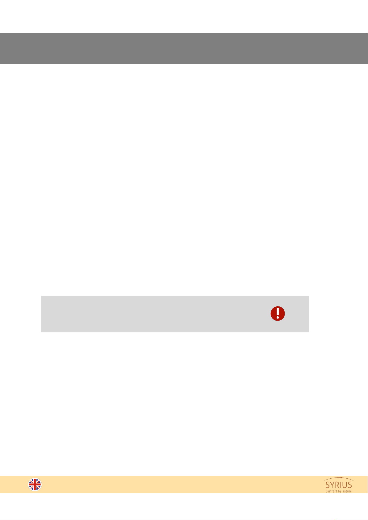
These installation instructions describe the installation of the TS-INOX solar water heater for a flating roof.
The main components of the system are as follows:
- Solar storage tank
- Solar collector(s)
- Mounting bracket
- Hydraulic kit
Detailed information can be found in the product nomenclature.
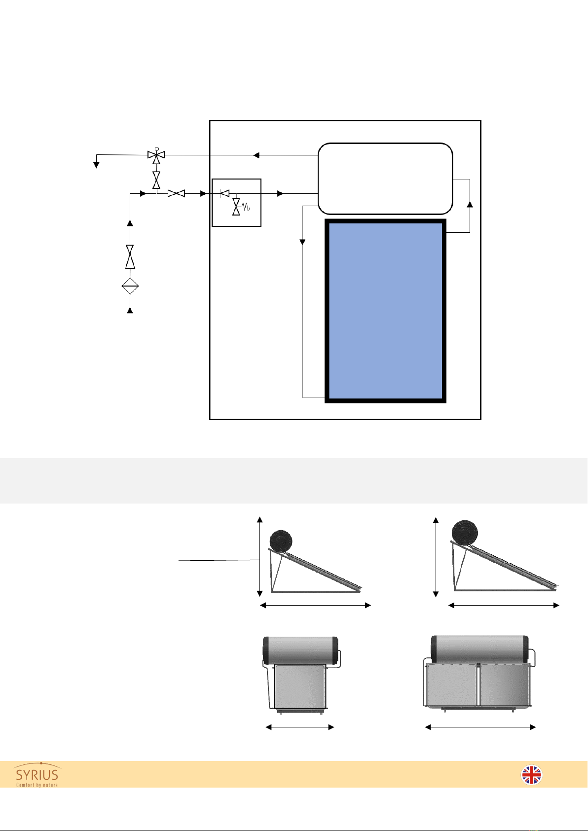
TS-INOX thermosiphon water heaters operate in direct circulation. The storage tank is protected against
corrosion (Inox 316L).
The hot water temperature in the storage tank can reach more than 100°C. The maximum operating pressure
is 7 bar. If the mains pressure is higher than 4 bar, it is necessary to use a pressure reducer.
For optimum performance, the solar collectors must face south in the northern hemisphere and north in the
southern hemisphere. To ensure the production of hot water all year round, it is possible to install an electric
back-up. To avoid burns and for greater comfort, it is necessary to install a solar thermostatic mixer.
How does a thermosiphon work?
The water, circulating inside the collectors heats up, expands and becomes lighter than cold water. It rises
naturally in the storage tank located above the collectors for the thermosiphon technology. This hot water
then replaces the cold water which goes back down to the collectors to be reheated, and so on.
It is a phenomenon of natural circulation of a liquid that uses the variation of its density with temperature.
Packaging, handling and storage
The collector is packaged in two cardboard covered, reinforced by honeycombed wedges on the corners.
The tank is wrapped in a protective foam, filmed with stretch plastic film. The supports are wrapped with
stretch film, as well as the tubes of the hydraulic kit. The products must be stored indoors. Do not handle the
collectors or the tank by the inlet/ outlet tubes. Protect the glass and the back of the collector during transport.
Maintenance
In order to ensure that the system functions properly over time, it is important to carry out all the maintenance
steps mentioned in the user manual. If these steps are not carried out, the longevity of the product and its
warranty may be affected.

V07.22 Page 7of 20
Safety instructions
Roof
Before installation, make sure
- that the roof can withstand the load of a TS-INOX water heater once filled.
- that the inclination is sufficient for the thermosiphon’s function (see page 6)
Local climatic conditions, such as snow and wind, must be taken into consideration. Please contact your
seller for more information.
Location
Make sure that there is enough space available for the correct installation of the system. Please observe
the distance to the roof edge of 1.5m. This is necessary with regard to roof statics, snow and wind loads,
as well as to facilitate maintenance of the system. If the roof does not allow this, please consult a structural
engineer.
Roof waterproofing
In order to avoid moisture and water infiltration problems on the roof, pipes that penetrate the roof must be
well sealed. The fixing of the supports is carried out by means of anchor bolts with sealing gasket.
Additional comments
The connecting pipes must be very well insulated to avoid heat loss and UV damage.
We recommend that you declare the TS-INOX water heater to your insurance company as an added value
to the building and take out insurance against lightning and glass breakage.
Be careful:On very sunny days, the collectors can become very hot. There is a risk
of burning. Therefore, the collectors must be covered during installation. Prefer an
installation in the early morning.

Page 8of 20 V07.22
Technical instructions
Installation guide
The installation of the water heater is described in detail on the following pages. These installation
instructions are divided into three parts:
1. Installation of collectors and storage tank
2. Hydraulics
3. Maintenance
Before starting the installation, please consider the following points:
The thermosiphon solar water heater must be installed with a minimum inclination of 15°, corresponding to the
limit of use.
Antifreeze corrosion protection
The TS-INOX thermosiphon water heater must not be installed in areas at risk of frost.

V07.22 Page 9of 20
Safety group
The safety groups protect the water heaters when the internal pressure reaches 7 bar. This also allows the
opening and closing of the water supply to the water heater and the emptying of the water heater by
operating the valve cap. The safety group must be connected to the gutter by means of a drain pipe. The
drain pipe must be free of obstructions so that the excess water can drain off normally.
Electric connection
Where a booster resistor is required, a circuit breaker must be installed. This installation must be carried
out by a certified electrician.
Lightning protection
The load-bearing structure of the collectors must be earthed. If a lightning protection device is already
provided for the building, the metal piping of the solar system must be connected to this device with a
green/yellow conductor cable with a minimum cross-section of 6 mm² Cu (H07 V-U or R). If this is not the
case, an earth spike can also be used for earthing.
Decommissioning and dismantling
The system must be dismantled early in the morning to avoid the risk of burning. Be aware of the system
temperatures before starting dismantling. Cover the collectors the day before if possible, to prevent the
passage of solar radiation.
Pictograms
Important instructions Possible danger or damage to the product
Necessary tools
Drilling / screwing machine Flat spanner
Multi-handling pliers
Flat and Phillips screwdriver Meter

Page 10 of 20 V07.22
Collectors and storage tank installation
View of flat roof support (STT) (4) for TS-202INOX
View of flat roof support (STT) (4) for TS-304INOX

V07.22 Page 11 of 20
Collectors and storage tank installation
Positioning the cement blocks:
Observe the dimensions given above for the positioning of the cement blocks.
Drill the blocks with an 8mm drill bit.
Tighten the soles (4.7) and (4.8) with the M8 anchor bolts
(5.5).
Assemble the spars (4.1) and (4.2), the rear feet (4.9) and
the braces (4.10) to the corresponding soles (4.7) and (4.8).
Use the screws (5.1) (5.2) (5.3) (5.4) to make the assembly.
STT TS INOX 202
STT TS INOX 304
Cement blocks
Minimum
dimensions :
200 x 200 x 200
4.7
4.8
4.9
4.10
4.2
4.1
5.1
5.3
5.4
5.2
LAYING METHOD

Page 12 of 20 V07.22
Collectors and storage tank installation
Put together the cross braces (4.11) to the rear feet (4.9).
Use the screws (5.1) (5.2) (5.3) (5.4) to assemble them.
Put together the collector crossarm (4.3 or 4.4) to the spares
(4.1) and (4.2).
Use the screws (5.1) (5.2) (5.3) (5.4) to assemble them.
4.11
4.3

V07.22 Page 13 of 20
Collectors and storage tank installation
Lift the collectors (3) on the roof. For lifting, attach two
sturdy ropes as shown opposite. During handling,
check that the rope doesn’t cover the copper inlet/
outlet tubes. It is recommended to use a crane for
lifting. If necessary, carefully use, a ladder to mount
the collectors on the roof. Work in pairs: one installer
secures the collectors, the other guides them.
Raise the tank on the roof. For assembly, attach two
sturdy ropes as shown opposite. We recommend
using a crane for lifting. Work in pairs: one installer
secures the tank, the second one guides the thank.
Observe the safety instructions! Don’t walk under
suspended loads.
Secure the collectors and the tank to prevent falls.
202INOX
Place the collector (3) on the mounting system.
202INOX
Screw the collector on the collector crossarm (4.3)
with M8 screws (5.1) and flat washers (5.3).
UP
Rear view of the
collector
3
5.3
5.1
5.3
5.1
5.3

Page 14 of 20 V07.22
Collectors and storage tank installation
304INOX
Place the collectors (3) on the mounting system.
304INOX
Connect the collectors with 22x22 fittings (6.6)
Be careful not to overtighten the connections. The
collectors tappings are fragile.
It is necessary to use 2 flat spanners, one to hold the
central nut to prevent rotation of the fitting, and another to
tighten the nut on each side. Failure to follow this protocol
will result in damage to the welds and the collector.
3
6.6

V07.22 Page 15 of 20
Collectors and storage tank installation
Remove the protective film from the bottom sheet of the tank
and fix the storage tank crossarms (4.5 or 4.6) to the storage
tank with the M8 screws (5.1) and flat washers (5.3).
The cold water inlet and hot water outlet must be on the left
side of the tank when standing in front of the water heater.
Place the tank (1) on the spares (4.1).
Screw the tank crossarms (4.5 or 4.6) to the spares with the
screws (5.1) (5.2) (5.3) (5.4).
Tighten all screw assemblies.
5.1
5.2
5.3
5.4
1
4.5
5.1
5.3
5.1
5.3
The tank must be positioned
horizontally

Page 16 of 20 V07.22
Hydraulics
Overview of the hydraulic connections of the TS-INOX 202:
(Refer to the page 3)
Overview of the hydraulic connections of the TS-INOX 304:
DHW
output
G3/4".
Solar starter
G3/4''
Solar inlet
G3/4''
Tube Ø22
Solar
return
Solar
inlet
Tank DHW
Arrival CW
G3/4''
Tube Ø22
Solar collector
6.7
6.2
6.10
6.7
6.1
6.9
6.3
6.4
6.4
6.5
6.2
6.9
Tube Ø22
Tube Ø22
6.7
Tube Ø22
Arrival CW
G3/4''
Ballon ECS
Solar
Inlet
DHW output
G3/4".
6.9
6.3
6.3
6.7
6.6
6.1
6.10
6.9
Solar collector
Solar starter
G3/4''
Tube Ø22
Tube Ø22
Solar collector
Tank DHW
Solar inlet
G3/4''
6.8
6.8

V07.22 Page 17 of 20
Hydraulics
Model 200L
Connect the hydraulic kits according to the following considerations:
Connect the flow pipe (6.1) between the storage tank and collector using the compression fittings (6.3) and (6.7).
The connection (6.7) at the tank connection must be sealed with sealing compound and thread (NO TEFLON).
Do the same with the coupling (6.4), then connect the return hose (6.2) using the compression fittings (6.4) and
(6.5).
Place the compression caps on the 2 remaining collector inlet/ outlet tubes.
Assemble the safety group (6.10) to the flask using a high-temperature fibre gasket or joint compound and thread.
Model 300L
Connect the hydraulic kits according to the following considerations :
Connect the flow pipe (6.1) between the storage tank and collector using the compression fittings (6.3) and the
loose nut (6.8) with the high-temperature fibre seal (6.9).
Likewise, connect the return pipe (6.2) using the compression fitting (6.3) and the loose nut (6.8) with the high-
temperature fibre seal (6.9).
Place the compression caps on the 2 remaining collector inlet/ outlet tubes.
Assemble the safety group (6.10) to the flask using a high-temperature fibre gasket or joint compound and thread.
Remove the remaining protective film from the storage tank before commissioning.
Filling the water heater :
-
Turn on a hot water tap in the dwelling.
-
Open the water supply, at the safety group level
-
Allow the air in the water heater to bleed through the hot water tap
open for this purpose.
-
When water flows out of the hot water tap, turn it off. This means
that the water heater is full.
Do not use Teflon
Be sure to use a thread to allow the system to be watertight.
Each screwed connection must be sealed with a wire rope.

Page 18 of 20 V07.22
Installation Checklist
System
Installation date
Customer's name
Customer's address
Tank serial number
Collector serial number
Installer name
INSTALLATION Checklist
Was the installation carried out in accordance with the rules on health and safety at work?
Has the system been installed according to this installation manual?
Is the minimum distance from the edges of the roof 1.5 m?
Have the pipe connections through the roof been properly sealed?
Are all screws and mechanical connections properly tightened and double checked?
Have the safety group, the pressure reducer and the thermostatic mixer been installed and their
use checked?
Are all hydraulic connections securely tightened and has the system been checked for leaks?
Has the cover on the collector been removed after installation?
Has the protective film on the storage tank removed before commissioning?
Does the system produce domestic hot water during sunny periods?
Has the customer been informed about the use of this system and have they been given to this manual?

V07.22 Page 19 of 20
Maintenance Checklist
System
Maintenance date
Customer’s name
Customer's address
Tank serial number
Collector serial number
Installer name
MAINTENANCE Checklist
Is the support in good condition? Are all the screws tight?
Is the tank in good condition and free of leaks or other damage?
Is the collector in good condition and free of leaks or other damage?
Is the pipe insulation in good condition?
Has the functionality of the valves and safety components been checked?
Are all hydraulic connections securely tightened and has the system been checked for leaks?
Does the system produce domestic hot water during sunny periods?

Page 20 of 20 V07.22
TECHNICAL DATASHEETS
(products, accessories...)
available on
www.syrius-solar.com
SYRIUS SOLAR INDUSTRY
15 rue du Perpignan - ZAC Descartes
34880 Lavérune – France
Tél. +33 (0) 4 67 82 00 18
contact@syrius-solar.fr
This manual suits for next models
2
Table of contents
Other SYRIUS Water Heater manuals
Popular Water Heater manuals by other brands

sylber
sylber DEVYL Bx 11 MTN Installation and user manual

Toyotomi
Toyotomi Oil Miser OM-148 (Type D) installation manual

Dewhot
Dewhot OD20DH manual

clage
clage German Pool DBN user manual

Heatrae Sadia
Heatrae Sadia Multipoint Instantaneous Fitting instructions

Watts
Watts Aerco SmartPlate EV Installation, operation & maintenance manual

Noritz
Noritz NRC111-SV installation manual

Thermann
Thermann TIHP300 owner's manual

A.O. Smith
A.O. Smith GPS-75 instruction manual

State Water Heaters
State Water Heaters 184671-000 instruction manual

Gorenje
Gorenje GWH12NFEAC User manual and installation instructions

AIC
AIC TEXAS 99 Installation and maintenance manual