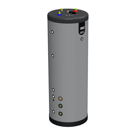
ACV LCA HP 2000 mh User manual

EN 1Document ref.: 428016 03
TECHNICAL MANUAL
INSTRUCTIONS FOR INSTALLATION AND USE
OF ELECTRIC WATER HEATERS AND
ENAMELLED HEATER TANKS
FROM 300 to 3000L

EN 2Document ref.: 428016 03

EN 3Document ref.: 428016 03
DATASHEET
Name of
supplier
Standing
losses
[W/H] 93,23 112,09 145,57 168,2 205,92 246,25 277,52 302,05
Storage
capacity
1550
1726
2550
2746
[l]
333
516
747
917
D
D
E
E
E
ErP class
Model
ACV
LCA P 300
LCA P 500
LCA P 750
LCA P 1000
LCA P 1500
LCA P 2000
LCA P 2500
LCA P 3000
-
C
C
D
Name of
supplier
Standing
losses
[W/H] 95,13 114,38 148,54 171,63 210,12 251,28 283,18 308,21
Storage
capacity
ErP Class
Model
ACV
LCA 300 hh
LCA 500 hh
LCA 750 hh
LCA 1000 hh
LCA 1500 hh
LCA 2000 hh
LCA 2500 hh
LCA 3000 hh
-
C
C
D
D
D
E
E
E
1551
1727
2551
2747
[l]
333
515
744
914
Name of
supplier
Standing
losses
[W/H] 163,54 186,63 225,12 266,28 298,18 323,21
Storage
capacity
1555
1731
2552
2748
[l]
748
918
E
E
E
E
E
ErP Class
-
D
ACV
Model
LCA 750 mh
LCA 1000
mh
LCA 1500
mh
LCA 2000
mh
LCA 2500
mh
LCA 3000
mh
Name of
supplier
Standing
losses
[W/H] 97,03 116,67 151,51 175,06 214,32 256,31 288,84 314,37
[l]
317
489
709
Model
LCA 1CO
300 hh
LCA 1CO
500 hh
LCA 1CO
750 hh
ErP Class
-
C
C
D
Storage
capacity
865
1508
1684
D
ACV
LCA 1CO
2500 hh
LCA 1CO
3000 hh
E
E
E
E
2485
2681
LCA 1CO
1000 hh
LCA 1CO
1500 hh
LCA 1CO
2000 hh
Name of
supplier
Standing
losses
[W/H] 166,81 190,36 229,62 271,61 304,14 329,67
869
1512
1688
E
ACV
LCA 1CO
2500 mh
LCA 1CO
3000 mh
E
E
E
E
2486
2682
LCA 1CO
1000 mh
LCA 1CO
1500 mh
LCA 1CO
2000 mh
[l]
713
Model
LCA 1CO
750 mh
ErP Class
-
D
Storage
capacity

EN 4Document ref.: 428016 03
DATASHEET
Name of
supplier
Standing
losses
[W/H] 98,94 118,96 154,48 178,5 218,52 261,33 294,51 320,54
Storage
capacity
ErP Class
Model
ACV
LCA 300
2CO hh
LCA 500
2CO hh
LCA 750
2CO hh
LCA 1000
2CO hh
LCA 1500
2CO hh
LCA 2000
2CO hh
LCA 2500
2CO hh
LCA 3000
2CO hh
-
D
D
D
D
E
E
E
E
1501
1657
2476
2672
[l]
317
489
711
870
Name of
supplier
Standing
losses
[W/H] 170,08 194,1 234,12 276,93 310,11 336,14
Storage
capacity
ErP Class
Model
ACV
LCA 750
2CO mh
LCA 1000
2CO mh
LCA 1500
2CO mh
LCA 2000
2CO mh
LCA 2500
2CO mh
LCA 3000
2CO mh
-
E
E
E
E
E
E
1505
1674
2486
2682
[l]
715
883
supplier
Standing
losses
[W/H] 121,24 157,45 181,93 222,73 266,36
[l]
480
676
Model
LCA HP 500
hh
LCA HP 750
hh
ErP Class
-
D
D
Storage
capacity
838
1467
1631
D
ACV
E
E
LCA HP
1000 hh
LCA HP
1500 hh
LCA HP
2000 hh
Name of
supplier
Standing
losses
[W/H] 173,35 197,83 238,63 282,26
842
1471
1635
E
ACV
E
E
LCA HP
1000 mh
LCA HP
1500 mh
LCA HP
2000 mh
[l]
680
Model
LCA HP 750
mh
ErP Class
-
D
Storage
capacity

EN 5Document ref.: 428016 03
CONTENTS
1. RECOMMENDATIONS 7
2. INSTALLATION 10
3. HYDRAULIC CONNECTION 11
4. HYDRAULIC TESTS 13
5. ELECTRICAL CONNECTION 14
6. INSTALLATION OF HEATING COMPONENTS 15
7. ELECTRICAL SPECIFICATIONS AND CABLING DIAGRAMS 17
8. PUFFER RANGE 24
9. DOMESTIC HOT WATER STORAGE RANGE 25
10. SINGLE COIL RANGE 26
11. HEAT PUMP COIL RANGE 27
12. DOUBLE COIL RANGE 28
13. INSTALLATION OF HYDRAULIC ACCESSORIES 29
14. INSTALLATION OF THE INSULATION 30
15. COMMISSIONING 31
16. SHUTDOWN OF THE SYSTEM 31
17. USER RECOMMENDATIONS 32
18. MAINTENANCE AND CLEANING 33
19. TROUBLESHOOTING 34
20. WARRANTY 35

EN 6Document ref.: 428016 03

EN 7Document ref.: 428016 03
1. RECOMMENDATIONS
1-1 General recommendations
1. This very important manual is an indispensable part of
the appliance.
The manual must be kept in a safe place and must be
passed onto any subsequent owners or users of the
appliance and/or in the event that the boiler is
transferred to another site.
2. Read the instructions and advice provided carefully, as
this will help you to ensure your appliance is safely
installed, used and maintained.
3. The purchaser is responsible for installation, which
must be carried out by an industry professional in
accordance with the instructions in the manual.
4. Any use of the appliance other than that stipulated
herein is prohibited.
The manufacturer shall in no way be held liable for any
damages arising from the improper, incorrect or
unreasonable use of the appliance or failure to follow
the instructions contained in this manual.
5. Installation, maintenance and all other operations
must be carried out by industry professionals according
to the applicable regulations and the indications
provided by the manufacturer.
6. The manufacturer accepts no liability for any personal
injuries, injuries to animals or damage to goods as a
result of any incorrect installation
of the appliance.
7. The packaging (clips, plastic bags, expanded
polystyrene, etc.) must be kept out of the reach of
children.
8. This appliance is not designed for use by persons
(including children) with reduced physical, sensory or
mental capacities, or who do not have sufficient
knowledge or experience, unless they have benefited
from supervision and instruction concerning the use of
the appliance by the person responsible for their safety.
9. Children must be supervised to ensure they do not
play with the appliance
10. Do not touch the appliance with your bare hands or
any wet body parts.
11. For all repairs, call an accredited technician and insist
that genuine spare parts are used. Failure to comply with
these instructions could compromise safety and shall
exempt the manufacturer from all liability. Before
carrying out any repair and/or maintenance operation
on the unit, it is important to isolate all supply sources.
In case of a malfunction in the unit, switch it off and
phone technical assistance.
12. No inflammable objects must be kept near the
appliance.
13. Correct usage also includes following the instructions
for use and installation, and adhering to any additional
documentation, as well as
the inspection and maintenance conditions.
14. Any use outside these conditions is forbidden.
1-2 User recommendation
Before installing the appliance, please read the
instructions in this manual carefully. Failure to comply
with them will invalidate the warranty.
The purchaser is responsible for installing the product.
Installation, start-up, maintenance and repairs must only
be carried
out by a qualified professional in accordance with
industry practice and applicable national standards. It is
essential to comply with all prescriptions relating to
domestic hot water tanks, as well as the instructions
supplied by the manufacturer.
To prevent burns, use suitable mixing devices to avoid
exceeding a temperature of 50°C at the catchment
points.
If the appliance is inactive for a prolonged period (e.g.
during winter holidays) in an unheated area, water may
freeze in the appliance and the pipes. Ensure that the
installation is protected from freezing.
If any accessories are installed on the unit, they must
only be original parts from the manufacturer.
To clean the exterior of the unit, it is recommended to
use a damp cloth and cleaning products intended for this
purpose.
The use of abrasive products or solvents is strongly
discouraged.
No inflammable objects must be kept near the
appliance.
GENERAL SAFETY STANDARDS
Failure to respect the warnings could result in injury and
may even lead to death.
Failure to comply with warnings could result in serious
damage to objects, plants or animals.
The general and specific safety standards relating to the
product must be observed.
Do not carry out any operation which requires the
appliance to be opened.
Burn injuries from hot components or injuries caused by
parts that protrude or by sharp edges.
Do not carry out any operation which requires the
appliance to be moved.
Contact with live components can cause electrocution.
Flooding caused by water escaping from disconnected
pipes.
Do not use the connector plug on the main supply cable
to connect or shut down the appliance.
Electrocution can be caused by a damaged cable, socket
or connector plug.
Do not damage the main supply cable.
Electrocution caused by stripped live wires.
Never place any objects on the appliance.
Injuries can be caused by the item falling due to
vibrations.
Damage to the appliance or items below it caused by
items that fall because of vibrations.
Do not climb on the appliance.
Injury can be caused by the appliance falling over.
Damage to the appliance or items below it due to the
appliance becoming detached from its supports and
falling over.
Do not climb on chairs, step stools, ladders or unstable
supports to clean the appliance.
Injury due to falling or folding of the ladder (double
ladder).
Do not carry out any cleaning operations on the
appliance without having switched it off, disconnected
the connector plug or deactivated the relevant switch.
Contact with live components can cause electrocution.
Install the appliance on a solid wall that will not be
subject to vibrations.
Noise during operation.
When drilling the wall, take care not to damage the
electrical cables or pipes.

EN 8Document ref.: 428016 03
Contact with live conductors can cause electrical arcing.
Explosions, fires or poisoning in the event of gas leaking
from a damaged duct.
Damage to existing installations. Flooding in the event of
water leaking from damaged ducts.
Protect connection cables to prevent them from being
damaged.
Contact with live conductors can cause electrocution
Flooding caused by water escaping from damaged pipes
Check that the part and the installations to which the
appliance will be connected comply with the current
applicable regulations.
Contact with incorrectly installed live conductors can
cause electrocution.
Damage to the appliance due to unsuitable operating
conditions.
Use accessories and manual equipment suitable for the
usage (ensure that the tool is not damaged and the
handle is securely attached and in good condition), use
this equipment correctly, protect it against being
accidentally dropped and store it after use.
Injury may be caused by flying debris or fragments, dust
inhalation, impacts, cuts, pricks and abrasions.
Damage to the appliance or to nearby objects caused by
flying debris or fragments, impacts or incisions
Use suitable electrical equipment (in particular, check
that the supply cable and connector plug are in good
condition and that rotating or alternating parts are
properly secured).
Use the equipment correctly, do not allow a trailing
supply cable to obstruct access, secure it to prevent
falling, and disconnect and store it after use
Injury can be caused by electrocution, projected shards
or fragments, inhaling dust, being hit, or cuts, pricks,
abrasions, noise or vibrations.
Damage to the appliance or to objects nearby caused by
projected debris or fragments, cuts, incisions.
Ensure that portable ladders are stable and sturdy and
will not slip, and that the rungs are in good condition.
Ensure that someone is present to ensure that ladders
cannot move when someone else is using them.
Injury due to falling or folding of the ladder (double
ladder).
Ensure that materials, components or equipment used
during installation cannot fall from height.
Injury or death due to collapsing and/or falling parts.
Ensure that mobile ladders are correctly supported and
sufficiently sturdy, that the rungs are in good condition
and not slippery, and that the rungs and platforms are
fitted with rails.
Injury due to falling.
When working at height (generally during use with
height differences of more than 2 m), ensure that there
is a safety rail surrounding the working area or that
personal equipment is used to prevent falling, that the
route of any potential fall is not obstructed by
dangerous objects and that any possible impact would
be cushioned by semi-rigid or deformable supports.
Injury due to falling.
Ensure that the health and safety conditions are
adequate in terms of lighting, ventilation, structural
soundness and emergency exits.
Injury caused by being hit, tripping, etc.
During work, wear personal protective equipment and
clothing.
Injury can be caused by electrocution, projected shards
or fragments,
inhaling dust, being hit, or cuts, pricks, abrasions, noise
or vibrations.
The utmost care must be taken during operations
inside the appliance, and contact with sharp edges
avoided.
Injury caused by cuts, pricks and abrasions.
Do not use insecticides, solvents or harsh cleaning
products for maintenance of the appliance.
Painted or plastic parts can be damaged.
Do not use the appliance for any use other than
standard household use.
The appliance may be damaged by operation overload.
Damage to incorrectly treated objects.
Do not allow children or inexperienced persons to use
the appliance.
Damage to the appliance may be caused by improper
use.
Electrical connections must be made using conductors
with a suitable cross section.
Fire due to overheating caused by current passing
through cables which are too small.
Protect appliances and nearby areas using suitable
equipment.
Damage to the appliance or to objects nearby caused by
projected debris or fragments, cuts, incisions.
Move the appliance using the necessary protective
equipment and with the utmost care.
Damage to appliances or nearby objects caused by
impacts, incisions or crushing.
Ensure that all equipment is stored in a way that makes
it simple and safe to handle; avoid creating piles which
are in danger of collapsing.
Damage to appliances or nearby objects caused by
impacts, incisions or crushing.
Reset any safety and control functions affected by an
operation on the appliance, and make sure that they
are operating correctly before it is put back in service.
Damage to or stoppage of the appliance due to
uncontrolled operating conditions.
Before working on roofs, structures, surfaces, etc.,
ensure that they are stable and suitable for the work to
be carried out.
Injury or death due to collapsing and/or falling from
height.
SAFETY STANDARDS SPECIFIC TO THE PRODUCT
Drain any components which contain hot water by
activating the drain before using them.
Injury caused by burns
Descale components in accordance with the
instructions in the safety sheet for the product in
question. Carry out the operation in a well-ventilated
area and wear protective clothing.
Avoid mixing different products and protect the
appliance and nearby objects.
Personal injury through skin and eyes coming into
contact with acidic substances, inhalation of ingestion of
harmful chemical agents.
Damage to the appliance or objects nearby due to
corrosion caused by acidic substances.
Do not carry out work on the product in strong
sunlight.
Injury caused by burns

EN 9Document ref.: 428016 03
TRANSPORT, STORAGE AND RECYCLING
INSTRUCTIONS
The appliance must be transported in accordance with
the pictograms hereunder on the packaging.
The appliance must be transported and stored in dry
conditions and freezing conditions must be avoided.
EU directive 2002/96/EC requires selective collection
and recycling of used electrical and electronic devices.
The "crossed-out wheeled bin" symbol on the appliance
indicates that the product must be disposed of
separately from standard household waste at the end of
its useful life, and must be brought to a waste sorting
centre for electrical and electronic devices or returned
to the seller when a replacement appliance is purchased.
DECLARATION OF CONFORMITY
Conformity of design and production
This product conforms to EU directive 97/23EC, article 3,
paragraph 3 concerning pressure equipment and
93/69/CEE relating to standard EN12897-2006 specific to
indirectly heated, unvented water heaters.
If the addition of a resistance is recommended by the
manufacturer (kit specified in the manual), this product
complies with the following European directives and
standards: LVD Directive (electrical safety) 2006/95/EC
EMC Directive 2004/108/EC.
DESCRIPTION OF APPLIANCES
Enameled tanks are designed for both the production
and storage of domestic hot water.
These tanks can be combined with both solar energy
systems and more common energy systems such as gas-
or oil-fired boilers.
The tanks are protected by an enamel covering applied
at 850°C, in accordance with the requirements of DIN
4753/3.

EN 10 Document ref.: 428016 03
B
A
D
C
2. INSTALLATION
IMPORTANT:
The appliance must be installed in accordance with professional good practice and in
compliance with the national regulations in force for hydraulic and electrical
connections, under the entire responsibility of the installer.
This appliance must be installed in covered premises, sheltered from frost and
having sufficient upper and lower ventilation.
Installation of the water heater with its raising feet (label A)
Installation of heating components (label B)
Installation of hydraulic accessories (Option)
Installation of safety unit + drain (Option)
Installation of M1 or M0 insulation (label D)
Hydraulic connection (label C)
Principle with 1 water heater
Principle with two water heaters in series
Hydraulic tests
Electrical connection
Assembly test
INSTALLATION OF THE APPLIANCE

EN 11 Document ref.: 428016 03
RECOMMENDATIONS
The appliance must be as close as possible to the supply stations.
For operations of maintenance or replacement of heating components, easy
access must be provided. (Fig 1)
Installation of raising feet (using the bolts provided) (Fig 2)
Either use of the lifting rings of the appliance (at the top of the appliance),
Or possibility of tilting the appliance (without lying it down), taking care not to
put stress on the cylinder of the tank and of course without impact.
For information any external marking may entail internal damage to the
appliance and will therefore invalidate the warranty.
Position the water heater in its final position.
Check the stability of the water heater.
3. HYDRAULIC CONNECTION
To enable optimal use of the water heater, we recommend that you carry out the
hydraulic connection as follows:
IMPORTANT NOTE
Not all appliances labelled on these installation diagrams are supplied by us.
However, the correct installation of the appliance in accordance with the national
regulations in force is under the entire responsibility of the installer.
SCHEMA DE PRINCIPE AVEC UN CHAUFFE-EAU
DE PRINCIPE AVEC UN CHAUFFE-EAU
DIAGRAM OF PRINCIPLE WITH ONE WATER HEATER
Capot électrique
Sleeves de raccordement
1.20m
0.30 m
0.30 m
0,15m
Figure 1
Figure 2
Key:
1 - Cold water inlet
2 - Stop valve
3 - Water filter
4 - Check valve
5 - Safety valve
6 - Degassing bottle with bleeder
7 - Supply points (with
thermostatic mixers).
8 - Homogenisation pump
(mandatory against
Legionnaire’s Disease)
9 - Connection sleeves
For special fitting
10 - Funnel to the drain
11 - Example special fitting
(plate exchanger)
12 - Loop pump
13 - Loop reheater
12
11
10
2
10
5
2
4
2
13
6
2
43
1
7
4
8
9
Electrical cover
Connecting sleeves

EN 12 Document ref.: 428016 03
13
10
7
4
2
12
2
8
2
4
8
2
4
10
10
2
4
5
2
2
10
2
23
54
2
6262
1
9 9
DIAGRAM OF PRINCIPLE WITH TWO WATER HEATERS CONNECTED IN SERIES/PARALLEL
IMPORTANT:
In the event of installation of battery appliances, it is imperative to install a safety valve specific to
each appliance.
Safety units for the whole of the range (as option) to be installed on each appliance.
These valves must be calibrated at 7 bar maximum and comply with NF.
NB:
Generally, with regard to combating the proliferation of Legionnaire’s Disease, it is
necessary to comply with the recommendations of the Conseil Supérieur d’Hygiène
Publique de France, and more particularly the conformity of materials and equipment
implemented in respect of the compatibilities defined on pages 59 & 61 of the risk
management guide linked to Legionella of November 2001
The quality of the water distribution pipes is very important.
Beware of connections between different metals; we advise you to comply with the
instructions of DTU 60-1.
Provide a dielectric insulating connection near to the appliance on each pipe connecting to
the water network.
Verify that the pressure of the distribution network does not exceed 5 bars.
Otherwise, install a pressure reducer upstream of the appliance and its safety
systems.

EN 13 Document ref.: 428016 03
To enable the expansion of the water in the water heater, the safety valve must be
fitted with a pipe which will allow this expansion to overflow into a funnel connected
to the drain. Under no circumstances must you reduce its diameter or close this pipe
with a plug or a stop valve. Plugging will invalidate the warranty of the appliance.
Fitting of a filter on the cold water inlet is strongly recommended in order to
eliminate foreign matter such as sand, gravel, sludge, etc.
It is imperative to install a T-square on the low pipe of the appliance enabling a direct
transition valve to be fitted in order to carr out shunts ad eliiate sludge
stagnating at the bottom of the tank.
Provide a degasser with air drain on the hot water outlet (evacuation of dissolved
gas).
Equip the water heater with a domestic circulating system for proper
homogenisation of the water volume
For the purposes of combating Legionella, it is imperative that any thermostatic
mixer is installed as close as possible to the supply points, in order to minimise the
water circuit to 40°, temperature for maximum proliferation of Legionella
There must be no cutout or regulation system between the tank and the safety valve
4. HYDRAULIC TESTS
Upon first filling with water, it is down to the installer to verify the seal of the upper flange
and the manhole, and to tighten the bolts if necessary.
After hydraulic connection of all pipes, and before carrying out the electrical cabling,
completely fill the appliance and pressurise it.
Check and rectify the watertightness of each connection.
After each intervention on the hydraulic installation, it is imperative to carry out a
hydraulic seal test

EN 14 Document ref.: 428016 03
5. ELECTRICAL CONNECTION
Before connecting the appliance, check that the power is off, that the appliance is full of
water and that it is watertight.
Recommendations for installation:
The electrical installation must comply with national regulations in force in the
country of installation. For France, see standards NF C 732OO and NFC 15100.
Install a general circuit breaker and calibrated protection upstream on the electrical
supply.
Use correctly sized ires refer to the aufacturers’ alues ad esure all
connections are fully tightened.
The components mentioned on the electrical diagrams are provided with the
electrical kits.
Each component and the tank must be connected to earth (via the sleeves situated
on the flange of the tank).
The resistances must be supplied using an electromagnetic switch (not provided).
Connect its electrical circuit and the loop pump using terminals C1 and C3 of the
terminal block.
Never block it manually.
Do not install manual override switches.
It must be sufficiently sized.

EN 15 Document ref.: 428016 03
6. INSTALLATION OF HEATING COMPONENTS
A) Single resistance platinum shielded (9Kw - 15Kw - 30Kw)
ASSEMBLY DIAGRAM
___________________________________________________________________________
B) Multi-resistance platinum shielded (45Kw - 60Kw)
ASSEMBLY DIAGRAM
5 4 3 2 54 3 2
Recommended order of assembly
0 - Assembly of the flange
with tightening to 3dN
1 - Installation of M10Pins
2 - Installation of the seal
3 - Installation of the
resistance (NB loop
downwards for 15 & 30
Kw model)
4 - 1 backflange (model 15 &
30 Kw)
5 - 6 M10 bolts
4 3 2
5
Duct for
thermostat
centre
1
Duct for
thermostat
sensor
1
Recommended order of assembly
0 - Assembly of the flange
with tightening to 3dN
1 - Installation of Pins M10
2 - Installation of seal
3 - Installation of resistance
(NB loop downwards for
15 & 30 Kw model)
4 - 1 backflange (Model 15
& 30 Kw)
5 - 6 M10 bolts
0
0

EN 16 Document ref.: 428016 03
C –Multi-resistance steatite
ASSEMBLY DIAGRAM
___________________________________________________________________________
D - Multi resistance screwed shielded
ASSEMBLY DIAGRAM
Duct for
thermostat
sensor
1
0
3
4
Recommended order of assembly
0Assembly of the flange with
tightening to 3dN
1Installation of seals, abutting
the head of the sheaths
2The sheaths must be
assembled by hand, using a
tube giving counterweight to
facilitate the engagement of
the thread of the sheath into
the sleeve
3Tightening of the sheaths
using a key.
4Installation of steatite
resistances.
Duct for
thermostat
sensor
1
0
3
Recommended order of assembly
0Assembly of the flange with
tightening to 3dN
1Installation of joints, abutting
the head of the resistances
2The resistances must be
assembled by hand, to
facilitate engagement of the
threads in the sleeve
3Tightening of the resistances
using a key.
2
2

EN 17 Document ref.: 428016 03
E - Coil with flange 1m² or 3m²
ASSEMBLY DIAGRAM
7. ELECTRICAL SPECIFICATIONS AND CABLING DIAGRAMS
A –Shielded platinum resistance (9 Kw - 15 Kw - 30 Kw)
Enamelled tank of 300 to 3000 litres with lateral flange DN110.
Enamelled tank of 750 to 3000 litres with lateral flange DN400.
Flange equipped with immersion resistance, straight (9 kW), bent (15 to
30 kW), directed towards the bottom of the tank, thus avoiding cold zones
and the proliferation of bacteria.
Resistance supply voltage 230 TRI, 400 V TRI without neutral.
Dual thermostat, regulation from 30 to 80°C and overheating safety device
at 95°C with manual reset.
Soft jacket cover, M1 fire classification, or steel cover, M0 fire
classification.
These appliances are delivered on a wooden pallet; the tank, insulation (if
M0 jacket, separate parcel) and the electrical kit are fixed to this.
Capacity in
litres
Power in
kW
Heating
time Delta
T 60K
Weight with jacket
Electrical diagram
Fig N°
In h,mn
M1
M0
Star
Triangle
In Kg
In Kg
300
9
2h20mm
109
117
1
2
500
9
3h55mm
135
143
1
2
750
9
5h40mn
235
243
1
2
15
3h30mn
235
243
3
30
1h44mn
235
243
4
45
1h19mm
238
246
5
60
0h50mm
238
246
5
1000
9
7h27mm
265
273
1
2
15
4h39mn
265
273
3
30
2h20mn
265
273
4
1000
45
1h43mm
268
276
5
60
1h09mm
268
276
5
1500
9
11h12mm
245
254
1
2
Duct for
thermostat
sensor
0
2
Recommended order of assembly
0 Installation of joint on the
flange.
1 Assembly of the flange fitted
with its coil on the tank and
tighten the bolts at 3dN.
2 Installation of cap.
1

EN 18 Document ref.: 428016 03
15
6h59mn
345
354
3
30
3h29mn
345
354
4
45
2h41mm
348
357
5
60
1h45mm
348
357
5
2000
9
14h56mm
374
383
1
2
15
9h20mm
374
383
3
30
4h39mn
374
383
4
45
3h27mm
377
386
5
60
2h21mm
377
386
5
2500
9
18h42mm
503
513
1
2
15
11h40mm
503
513
3
30
5h49mn
503
513
4
45
4h25mm
506
516
5
60
2h57mm
506
516
5
3000
9
22h25mm
541
552
1
2
15
14h00mm
541
552
3
30
7h00mn
541
552
4
45
5h15mm
544
555
5
60
3h28mm
544
555
5
ELECTRIC DIAGRAM
Supplied with the kit
Supplied by installer

EN 19 Document ref.: 428016 03
CABLING DIAGRAMS
Fig N° 1
Star Cabling 9 kW (3x400 V)
ID
TYPE
SECTION
COLOUR
QTY
1
Control
1.5mm²
Red
2
2
Power
10 mm²
Black
3
3
Earth
10 mm²
Green/Yellow
2
4
Power connection
6 mm²
Black
4
Bloccond.protec.cap
16 mm²
Green/Yellow
1
L
Unit block 1 jonc
16 mm²
Grey
3
C
Unit block 1 jonc
5-6 mm²
Grey
3
Fig N° 2
Triangle Cabling 9 kW (3x230 V)
ID
TYPE
SECTION
COLOUR
QTY
1
Control
1.5mm²
Red
2
2
Power
10 mm²
Black
3
3
Earth
10 mm²
Green/Yellow
2
4
Power connection
6 mm²
Black
5
Bloccond.protec.cap
16 mm²
Green/Yellow
1
L
Unit block 1 jonc
16 mm²
Grey
3
C
Unit block 1 jonc
5-6 mm²
Grey
3
Fig N° 3
Triangle Cabling 15 kW (3x400 V)
mise à la terre
mise à la terre
de la cuve
de la bride
4
2
3
A
B12
C1 C2
L1 L2 L3
5
1
ID
TYPE
SECTION
COLOUR
QTY
1
Control
1.5 mm²
Red
2
2
Power
10 mm²
Black
3
3
Earth
10 mm²
Green/Yellow
2
4
Power connection
6 mm²
Black
1
5
Power bar
6 mm²
Brass
2
Bloccond.protec.cap
16 mm²
Green/Yellow
1
L
Unit block 1 jonc
16 mm²
Grey
3
C
Unit block 1 jonc
5-6 mm²
Grey
3
Fig N° 4
Triangle Cabling 30 kW (3x400 V)
ID
TYPE
SECTION
COLOUR
QTY
1
Control
1.5 mm²
Red
2
2
Power
10 mm²
Black
3
3
Earth
10 mm²
Green/Yellow
2
4
Power connection
6 mm²
Black
4
5
Power bar
6 mm²
Brass
5
Bloccond.protec.cap
16 mm²
Green/Yellow
1
L
Unit block 1 jonc
16 mm²
Grey
3
C
Unit block 1 jonc
5-6 mm²
Grey
3
mise à la terre
mise à la terre
de la cuve
de la bride
4
54
2
3
1
A
B12
C1 C2
L1 L2 L3

EN 20 Document ref.: 428016 03
Bulbe de sécurité
Bulbe de régulation
Fig N° 5
Triangle Cabling 45 kW / 60 kW (3x400 V)
Safety bulb
Regulation bulb
This manual suits for next models
58
Table of contents
Other ACV Water Heater manuals

ACV
ACV HeatMaster 60 User manual

ACV
ACV WaterMaster 25 Evo Owner's manual

ACV
ACV HeatMaster 25 C Assembly instructions

ACV
ACV Smartline Multi Energy 210 Owner's manual

ACV
ACV BNE 1 Assembly instructions

ACV
ACV Smart ME 200 Manual

ACV
ACV Solo 18 Owner's manual

ACV
ACV WaterMaster 25 User guide

ACV
ACV COMFORT 45 Product manual

ACV
ACV smart line E Series User manual
Popular Water Heater manuals by other brands

JOOLCA
JOOLCA HOTTAP V2 user guide

Webasto
Webasto Thermo 90 installation instructions

Rheem
Rheem RTG2-42 troubleshooting manual

Bock Water heaters
Bock Water heaters Electric Water Heaters Specification sheet

Armstrong
Armstrong Flo-Direct installation guide

Bosch
Bosch TR8500 21/24 DESOAB operating instructions