INSTRUCTION
Read this instruction before installation
and wiring of the product
HMH / HMH2 / HPH 1
HMH / HMH2 / HPH
Duct/wall humidistat
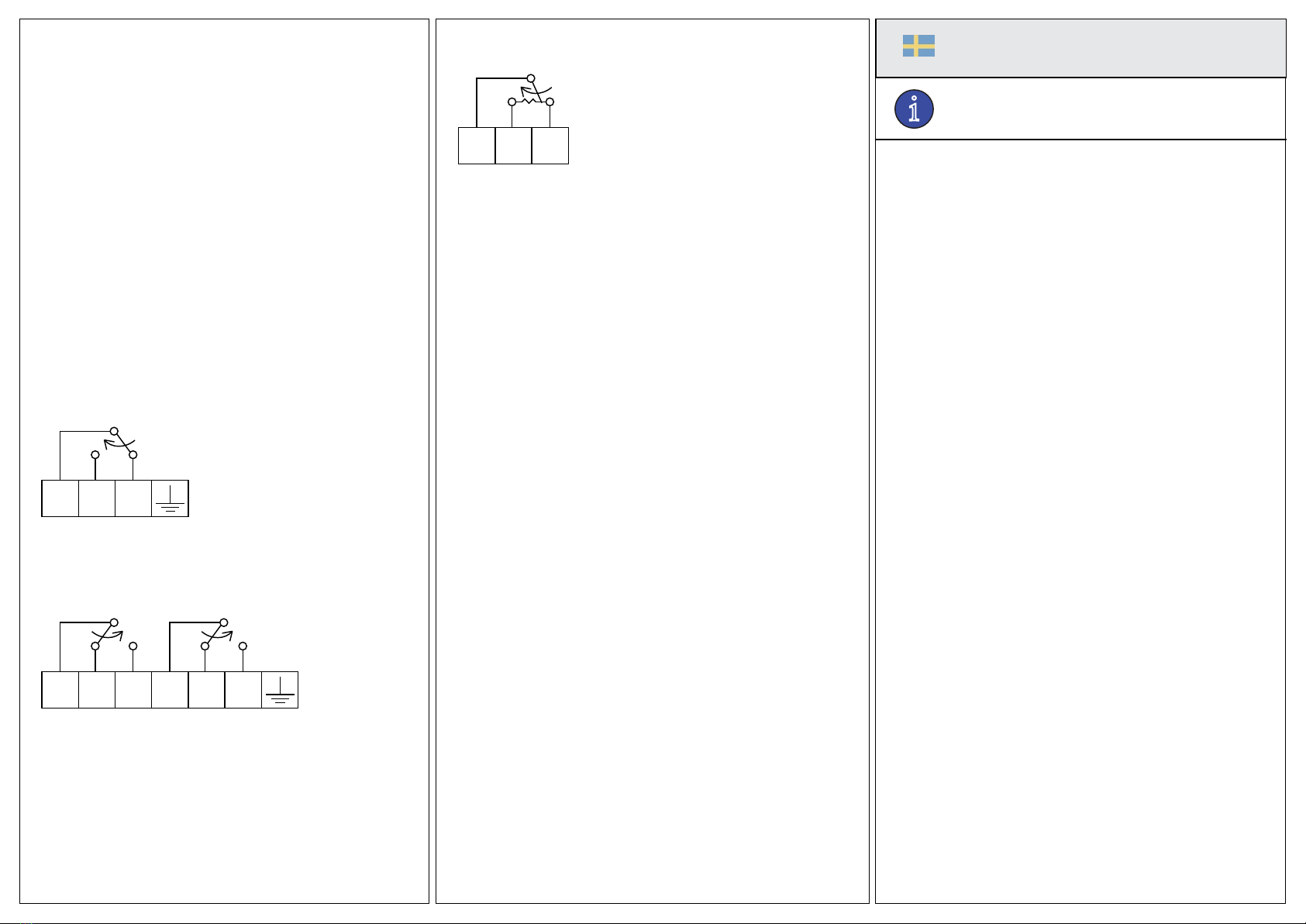
HMH, HMH2 and HPH are electromechanical humidistats with
change-over contact. They are not suitable for direct current circuits.
The following parts are supplied:
• L-shaped fastening bracket (on the back of the humidistat)
• Screw (4 mm in diameter) to lock the bracket to the humidistat
when duct mounting
• Cable conduit with fastening nut (two sets for HMH2)
Technical data
Maximum permitted temperature
at the sensor 70°C
at the casing 60°C
Microswitch (1-pole) 10 A, 250 V AC resistive at 25°C
Change-over contact 8 A, 250 V AC resistive at 60°C
HPH
Potentiometer resistance 148 Ω (HPH148), 1000 Ω (HPH1000)
Max. voltage 24 V
Setting range 10...100 % RH
P-band 7 % RH
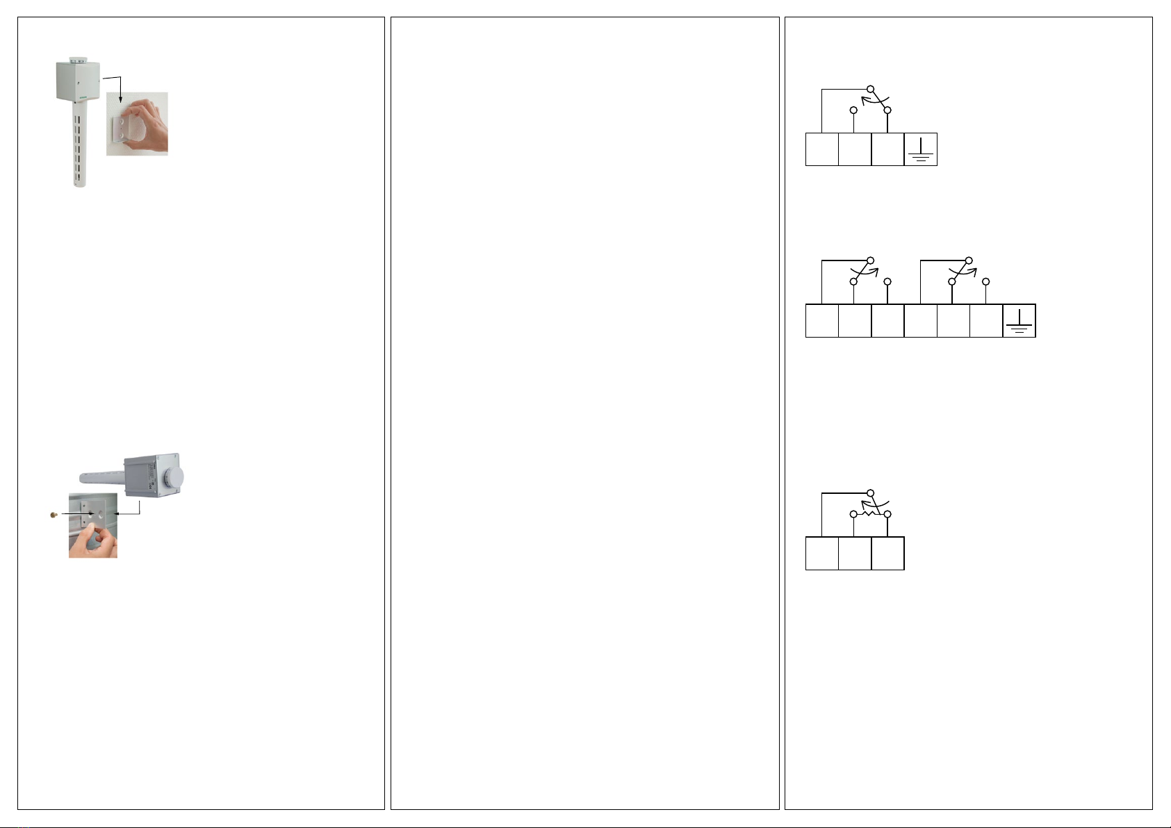
Installation
Remove the humidistat lid and mount the cable conduit.
Wall mounting
The humidistat should be mounted at a location with steady temperature
and air humidity and with good air circulation. Unsuitable locations are
outside walls, walls exposed to direct sunlight, corners, close to radiators/
boilers etc.
1. Slide the mounting bracket off the back of the humidistat.
2. Mount the bracket at a suitable location with the short ange pointing
down and out from the wall.
3. Hang the humidistat on the bracket with the stem pointing down.
Duct mounting
1. Make a hole (34 mm in diameter) at a suitable location on the duct.
The hole should not be placed on the underside of the duct. There
must be a free space of 350 mm out from the duct. Insertion depth:
222 mm.
2. Slide the fastening bracket off from the humidistat and turn it back to
front so that the short ange points out from the back of the humidi-
stat.
3. Insert the humidistat sensor through the hole in the duct and mark
out the positions of the fastening bracket screw holes. Note: At air
velocities greater than 5 m/s, the humidistat should be placed with
the venting holes in the stem at right angles to the air ow.
4. Drill holes in the duct for the fastening screws and screw the humidi-
stat in place.
5. Put the extra screw in the threaded hole in the bracket and screw it
to the back of the humidistat.
Maintenance
Calibrate the humidistat after it has been installed. Thereafter
calibrate it at regular intervals, e.g. at the beginning of every heat-
ing season. If dust or other matter is permitted to accumulate on any
type of sensor element, regardless of material (hair, cotton or plastic),
its hygroscopic interchange with the surrounding air will decrease.
Therefore, remove dust and other matter at regular intervals (in
connection with routine calibration). Use a soft brush. Regeneration
(washing the element) is not to be done if the humidistat functions
normally, but only if controlling precision is unsatisfactory (e.g. if the
sensor element is contaminated with grease).
Washing the hair element:
Remove the protection tube. Turn the setting knob to the minimum
value so the element is slack. Remove the hair element by pulling out
the split pins. Wash the element in e.g. hair shampoo and lukewarm
water. Rinse thoroughly.
When tting a new hair element, this should rst be soaked in water.
Then turn the knob to the maximum value. Calibrate the humidistat
when the element is completely dry and check the calibration a day or
two later.
Calibration
HMH
1. Measure the relative air humidity near the humidistat using for
example a whirling psychrometer.
2. Set the knob at the measured value.
3. Remove the plastic lid.
4. Turn the calibration nut to a position where the microswitch
clicks. Then turn the nut back a little and the microswitch will
click again. Set the nut to a point between the two click positions.
Do not breathe on the hair element during calibration since this
will affect the calibration.
5. Replace the plastic lid and set the knob at the desired control
value.
HMH2
1-3. The same as for HMH (see above).
4. Turn the calibration nut to a position where the microswitches
click. Then turn the nut back a little and the microswitches will
click again. Set the nut to a point between the two click positions.
5. Turn the differential screw anti-clockwise to set the desired dif-
ferential between the switches. Do not turn the screw more than
3/4 of a circle round, corresponding to approx. 25 % RH.
6. Replace the plastic lid and set the knob at the desired control
value.
7. Test the function under normal working conditions and adjust if
necessary.
8705A
NOV 11
EN