Tahoe TI3 KGP80B Datasheet


1
CONTENTS
MAIN TECHNICAL PARAMETER AND SPECIFICATIONS…2
ⅠMain Technical Specifications ………………………………………………………2
MAIN STRUCTURE AND USE METHOD……………………………4
ⅠStructure ……………………………………………………………………………4
ⅡMain Point of Use …………………………………………………………………4
ⅢProcedure of Use …………………………………………………………………4
ⅣUse and Maintenance ………………………………………………………………5
ⅤInstallation of Connective Pipe ……………………………………………………6
ANALYSIS OF MALFUNCTION AND REMEDY……………………7
PARTS DRAWING OF SELF-PRIMING PUMP………………………9
ⅠDetailed list of Parts for 2” self-priming pump ………………………………11
ⅡDetailed list of Parts for 3” self-priming pump ………………………………11
Ⅲ
Detailed list of Parts for 4” self-priming pump …………………………………12
ⅣDetailed list of Parts for 1.5” self-priming high-pressure pump …………………13

2
WARNING
PLEASE READ AND UNDERSTAND THIS MANUAL COMPLETELY BEFORE OPERATING THE EQUIPMENT.
MAIN TECHNICAL PARAMETERS AND SPECIFICATIONS
Ⅰ
ⅠⅠ
ⅠMAIN TECHNICALSPECFICATIONS
GASOLINE PUMPS
MODEL KGP80B
Inlet/outlet Diameter. (mm) 80(3”)
Max. head (m) 19
Max. Suction head (m) 8
Self-primin
g pump
Max. Capacity (m
3
/h) 60
MODEL 168F-1
Displacement (cc) 196
Max. Output (hp/rpm) 6.5/3600
Oil Capacity (L) 0.6
Engine
Fuel tank capacity (L) 3.6
Net Weight (Kg) 33
Pump unit
Net Dimension
L×W×H (mm) 505×370×442
K G P 50 B
Light combustion fuel tank
Model
Water pump
Gasoline engine
K G P 40 H
High pressure
Model
Water pump
Gasoline engine
Model

3
·
··
·MAIN STRUCTURE AND USE METHOD
Ⅰ
ⅠⅠ
ⅠSTRUCTURE
This type of pump consists of gasoline/diesel engine and water pump which drove by a same
driving axle. The pump is fixed on a frame through shock absorber device, so it compact in structure
and convenience for use of movement. For structure of self-priming pump.
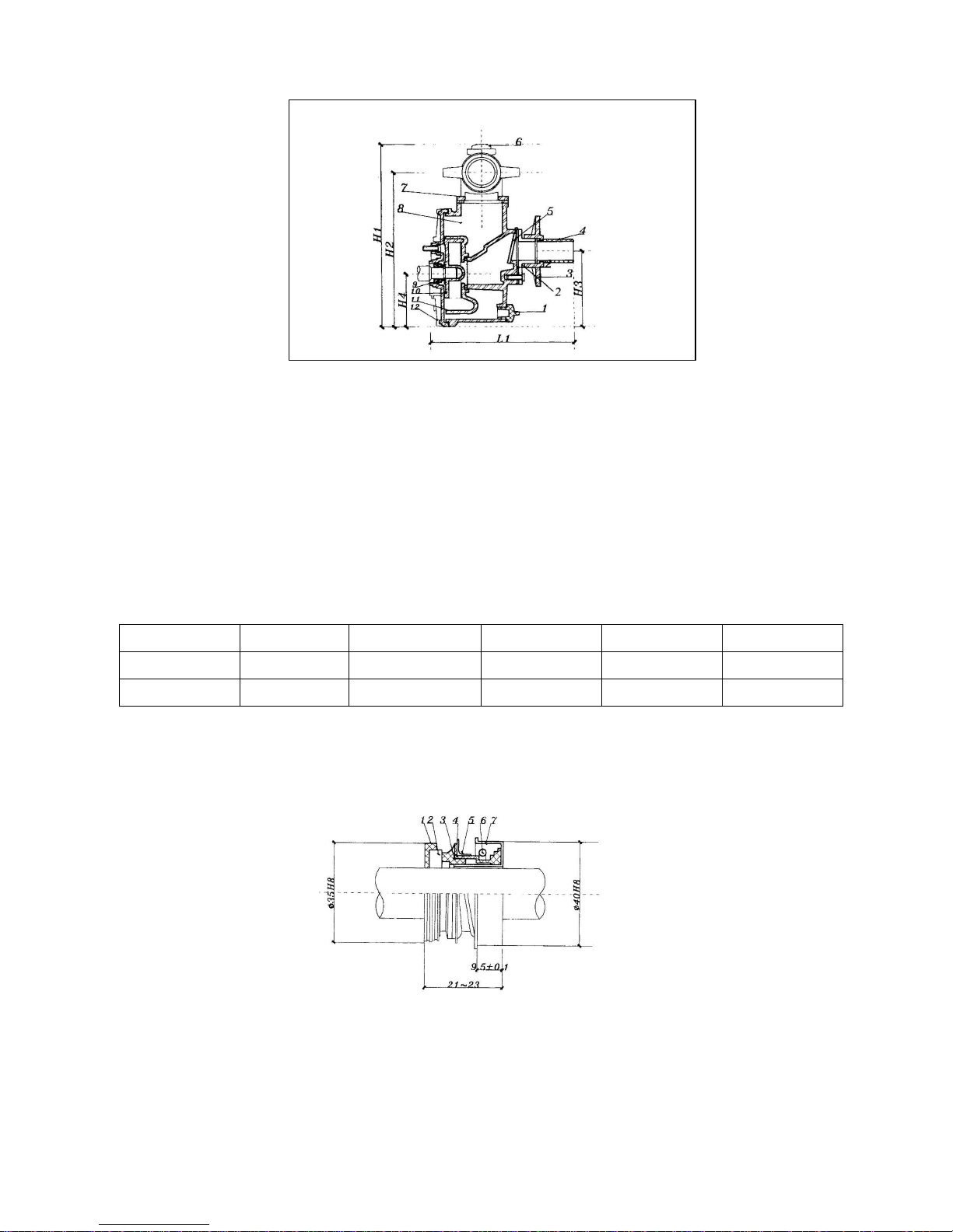
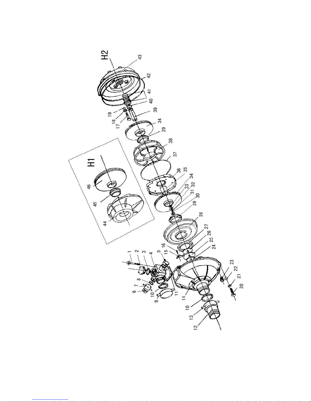
The pump consists of pump body, pump cover, flow guidance, impeller and seal part etc. The
pump body and pump cover are made from high quality die-casting of aluminum alloy. The flow
guidance and impeller are made from high strength cast iron, shaft sealing is machinery type sealing.
The suction and discharge pipe connector are made from engineering plastic so it can be connected
with rubber pipe.
The outlet of pump is higher than the inlet of impeller so that it can start which only need fill
water into the body of the pump. The inlet of pump is fixed with a one-way valve to prevent liquid
from being drained into water pool from the pump body which action by siphon after stop the machine.
It must guarantee store enough liquid in the pump body for next start.
The rotary direction is anticlockwise as viewed from inlet direction of impeller.
Ⅱ
ⅡⅡ
ⅡMAIN POINT OF USE
The coupling of suction pipe to the pump must be tight, reliable and no leakage.
A filter net must be added into the inlet of suction pipe as a protection , so as to avoid impurity be
sucker into the pump and stick or damage the impeller.
Prime the pump until the water overflow.
Do not run it at high speed, unless you prime it.
Drain off the pump for storage.
Ⅲ
ⅢⅢ
ⅢPROCEDURE OF USE
1. Adding water
When start the pump for the first time, it only need to add a few water into the pump and self-priming
after start, so not necessary bottom valve.
2. Start the engine, Please see manual of diesel engine or gasoline engine.
Ⅳ
ⅣⅣ
ⅣUSE AND MAINTENANCE
1.According to normal stipulation, the vacuum of pump by suction be expressed with allowable NPSH
(Net Positive Suction Head). When the pump work at the area of lower than 250m altitude. It can
estimate suction head of pump which 10m minus allowable NPSH is it. Follow increasing with
altitude, the atmosphere should be decreased, so the suction head of pump also be decreased. The
value of decrease can be estimated which 10m minus local atmosphere value is it (m water column).
2.Pipeline is better with short pipe and straight pipe, so it can decrease unnecessary loss of pipeline.
The pipeline must be supported to avoid from vibrating and damaging the pump by oppressive.
Before operation it must check connection part between pump and pipeline whether there is loose
phenomenon and special pay attention to leakage of inlet pipeline.
3.The filter net must keep a certain distance between river surface, river bottom and river bank. The
net must dip into water no less than 0.3m to avoid suction air and to keep a distance, which is not
less than 0.2m from river bottom, river bank to avoid suction stone or weeds.
4.If the gap between impeller and the surface of flow guidance is over 1mm, so that it can be

4
continuous to be used after adding an adjustment shim on the shaft shoulder.
Fig .1 Structure diagram of self-priming pump
1)Drain screw cock 2)Connector of inlet pipe 3)Tighten net of inlet pipe 4)
Connector
5)Door valve 6)Screw cock of adding water 7)Elbow of outlet 8)
Case of pump
9)Machinery seal 10)Impeller 11)Flow guidance 12)Pump cover
OVERALL DIMENSIONS TABLE OF SELF-PRIMING PUMP
Unit: mm
Type H1 H2 H3 H4 L1
50B 348 297 151 106 248
80B 410 348 171 106 325
5.When change machinery seal, be sure to apply adhesive to the connection between steel part
“#7”and pump cover. When fixed it, do not hit by force to prevent wear slice fracture.
Fig .2 Structure diagram of machinery seal.
1. Seal ring 2. Ceramics moving ring 3. Graphite static ring
4. Corrugated pipe 5.Washer 6.Spring 7. Steel part

5
6.When the pump is used in winter, to screw off the drain cock under the pump and draw off water
thoroughly after stop the machine to prevent from being broken by ice of freeze.
Ⅴ
ⅤⅤ
ⅤINSTALLATION OF CONNECTIVE SOFT PIPE
Set the rubber soft pipe on the connector of inlet pipe. Pay attention to, it must be set over the thread,
and then tighten it with clipper joint.
ANALYSIS OF MALFUNCTION AND REMEDY
MAL-FUNC
TION CAUSE REMEDY
Fill water is not enough Refill water into the pump.
Inlet pipe leakage. Check inlet pipe and connector of
pipe, change pipe or tighten the
screw of clipper joint.
Speed of pump is too low. Check speed and find cause for
remedy.
The filter net is obstructed. Check and clean up.
It is over the capacity of pump which will
be used lift or total lift. Check the position of installation and
remedy according to the cause.
The pump can not do pumping
Seal wear and leakage. Change machinery seal part.
The filter net, pipeline or impeller is
obstructed. Clean up the obstruction.
Speed is now. Increase speed.
Impeller or seal is wore seriously and the
gap is too large. Adjust the gap or change impeller
and machinery seal part.
Inlet pipe leakage. Check inlet pipe and connector of
pipe, change pipe or tighten the
screw of clipper joint.
The flow of water is not
enough.
Impeller damage and leakage seriously. Change impeller into a new one.
The total lift is too high. Check cause and adjust.
There is air in the pump or inlet pipe and
seal leakage.
Screw off air drain screw cock, and
eliminate the air.
Check the pipeline or change
machinery seal part.
The flow of water is not
well-distributed and sometimes
large, sometimes small.
Speed of engine is not stability. Adjust the speed of engine.

6
There is a rub between impeller and flow
guidance.
Listen to the sound carefully,
whether the impeller is clashed with
the case and then to adjust.
Power
consumption of
pump is too
large.
The impeller is obstructed by weeds or
foreign matters. Check and clean up.
The connector of inlet pipe is loosed or
leakage. Check inlet pipeline and remedy.
No flow
suddenly
Suction head is over stipulation. Check suction head and low the
position of pump.
MAL-FUNCT
ION CAUSE REMEDY
Suction head is too high and cause
cavitation. Check suction head and lower the
position of pump.
Out put of water is too large. Decrease the output of water.
Inlet pipe is obstructed by foreign body so
the resistance is too large. Check inlet pipe and filter net to
clean up.
Rotary part is loosed. Listen carefully and inspect the part
which cause the noise and stop the
machine to adjust.
Installing for pump unit is not stability. Stop the machine for checking and
adjusting.
There is air lay up in the pump or pipeline.
Screw off air drain screw cock and
eliminate the air.
Cause vibration or noise
Impeller damage. Stop the machine for checking and
change the impeller with a new one.

7
·
··
·PARTS DRAWING OF SELF-PRIMING PUMP

8
PARTS DRAWING OF SELF-PRIMING HIGH-PRESSURE PUMP

9
Ⅰ
ⅠⅠ
ⅠDetailed list of part for 2’’self-priming pump
No. Code Name Qty Remarks
1 screw 2
2 GB3452.1-82 seal ring 35502500 2
3 GB5783-86 bolt M8×25 15
4 GB97.1-85 washer 8 16
5 case of water pump 1
6 washer 1
7 diversion device 1
8 impeller 1
9 machinery seal 1
10 GB900-76 bolt M6×50 2
11 seal ring 1
12 cover of water pump 1
13 GB900-76 bolt M6×55 1
14 GB923-76 bolt M6 3
15 elbow 1
16 gasket 2
17 nut 2
18 connector 2
19 gasket 1
20 clap door 1
21 inlet connecting pipe 1
22 GB5782-86 bolt M6×25 4
23 filter net 1
24 connecting pipe 1
25 GB97.1-85 washer 6 4
26 GB6172-86 net M6 4
27 throat clip 3

10
Ⅱ
ⅡⅡ
ⅡDetailed list of part for 3’’self-priming pump
No. Code Name Qty Remarks
1 screw 2
2 GB3452.1-82 seal ring 35502470 2
3 GB5783-86 bolt M10×25 12
4 GB97.1-85 washer 10 12
5 case of water pump 1
6 gasket 1
7 diversion device 1
8 impeller 1
9 machinery seal 1
10 GB900-76 bolt M6×55 3
11 seal ring 1
12 cover of water pump 1
13 GB900-76 bolt M6 1
14 GB923-76 bolt M6 3
15 elbow 1
16 gasket 2
17 nut 2
18 connector 2
19 gasket 1
20 clap door 1
21 connecting pipe 1
22 GB5782-86 bolt M8×30 4
23 filter net 1
24 connecting pipe 1
25 GB97.1-85 Gasket 8 4
26 GB6172-86 net M8 4
27 throat clip 3

11
Ⅲ
ⅢⅢ
ⅢDetailed list of part for 4’’self-priming pump
No. Code Name Qty Remarks
1 screw 2
2 GB3452.1-82 seal ring 35502470 2
3 GB5783-86 bolt M10×25 12
4 GB97.1-85 washer 10 12
5 case of water pump 1
6 gasket 1
7 diversion device 1
8 impeller 1
9 machinery seal 1
10 GB900-76 bolt M6×55 3
11 seal ring 1
12 cover of water pump 1
13 GB900-76 bolt M6 1
14 GB923-76 bolt M6 3
15 elbow 1
16 gasket 2
17 nut 2
18 connector 2
19 gasket 1
20 clap door 1
21 connecting pipe 1
22 GB5782-86 bolt M8×30 4
23 filter net 1
24 connecting pipe 1
25 GB97.1-85 Gasket 8 4
26 GB6172-86 net M8 4
27 throat clip 3

12
Ⅳ
ⅣⅣ
ⅣDetailed list of part for 1.5” self-priming high-pressure pump
No. Code Name Qty Remarks
1 GB5787-86 Screw M8×60 4
2 Plastic plug 1
3 “O” rubber seal 1
4 elbow 1
5 Outlet cap 2
6 connector 1
7 nut 1
8 gasket 1
9 Outlet cap 1
10 gasket 1
11 gasket 1
12 connector 1
13 nut 1
14 case of water pump 1
15 Bottom valve 1
16 Screw M4×12 1
17 GB5787-86 Screw M8×40 4
18 GB97.1-85 Washer 4
19 “O” rubber seal 4
20 GB5787-86 Screw M8×35 8
21
Spring washer
8
22 Nut M8 8
23 Draining plug 1
24 Bottom valve weight 1
25 Diffuser 1
26 Valve 1
27 Rubber seal 1
28 Cover 1
29 Plastic bush 2
30 GB5787-86 Screw M10×15 1
31 Spring washer φ10 1
32 GB97.1-85 Washer φ10 1
33 Seal 1
34 Impeller 2
35 Aluminum pipe 1
36 Impeller 1

13
No. Code Name Qty Remarks
37 “O” rubber seal 1
38 Diffuser 1
39 Axle 1
40 Axle fence washer 1
41 Mechanical seal 1
42 “O” rubber seal 1
43 Pump casing 1
44 Diffuser 1
45 Plastic bush 1
46 Impeller 1
Table of contents
Popular Water Pump manuals by other brands

Wilo
Wilo COF-2 BL Installation and operating instructions

webtrol
webtrol TC Series instructions

Liberty Pumps
Liberty Pumps 2448 Series installation manual

Grundfos
Grundfos JP PS Series Installation and operating instructions

Kärcher
Kärcher 2.641-790.0 manual

Pentair
Pentair STA-RITE CM Series instruction manual

Dover
Dover PSG WILDEN PS4 Series Engineering, operation & maintenance

ProMinent
ProMinent Makro/ 5 M5Ka operating instructions

GÜDE
GÜDE KTP 18-0 Translation of the original instructions

ProMinent
ProMinent Makro TZ operating instructions

Gardena
Gardena 4000/4 Inox Multi 3 operating instructions

Agilent Technologies
Agilent Technologies 1260 Infinity II user manual