XR-1016FX/XR-1824FX 模拟调音台
24
25
26
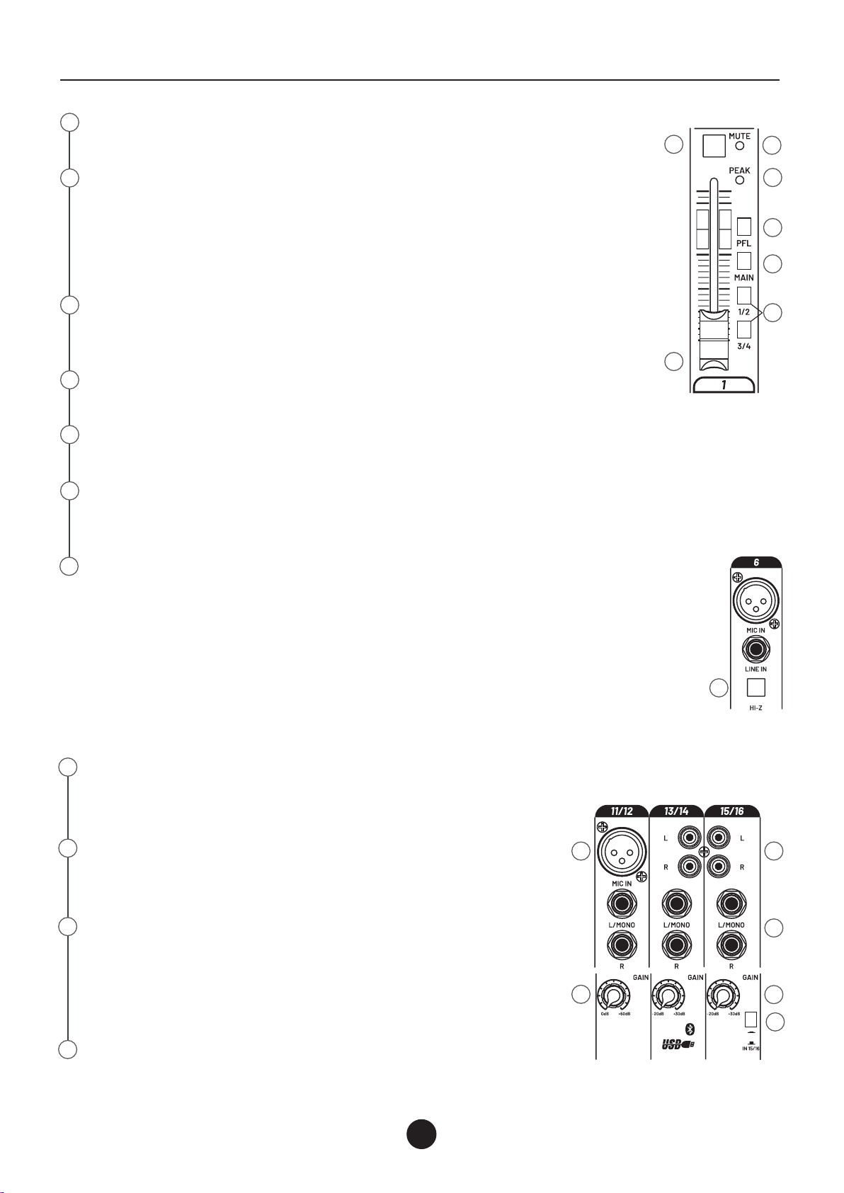
FX 脚踏开关
FOOT SWITCH 这个1/4"TRS连接器是接脚踏开关的地方,通过脚
踏开关可以开启和关闭内部效果,如果内部效果通道已被静音,
则脚踏开关工作无效。
耳机输出
这个 1/4" TRS 连接器为立体声耳机提供输出。该通道输出音量通
过PHONES音量控制旋钮控制。
左/右主输出
左/右输出具有2个 1/4" TRS Z 平衡插孔和2个全平衡 XLR 输出。
1/4" 输出可与Tip, Ring, Sleeve (TRS) 平衡或 Tip, Sleeve (TS) 非平
衡连接器一起使用。输出电平由主电平推子 (39) 设置。2个输出可
同时使用。
控制室输出插孔
这些 1/4" 插孔通常连接到控制室的输入放大器或耳机分配放大器。
幻象电源(XR-1824FX有2个)
该开关向输入 XLR 连接器施加 +48 VDC 电压,以为需要幻象电源
的麦克风供电。如果使用幻象电源,请勿连接不平衡动态麦克风
或其他无法处理此电压的 XLR 输入设备。
效果路由到AUX1-3
此发送允许将 FX 返回通道中的信号路由到 AUX1-3 发送。
AUX3 推子前/推子后按键
此按钮允许选择 AUX3/FX 位于推子前或推子后。
AUX1-4 MASTER
这些电位器控制辅助发送AUX1-4主电平。
按下 PFL按钮时,可以通过连接到 CTRL ROOM OUTPUT 的扬声器
(参见本手册的[27] 部分)或通过连接到 PHONES OUTPUT 的耳机
(参见第 [25] 部分)收听单个辅助输出中存在的信号。
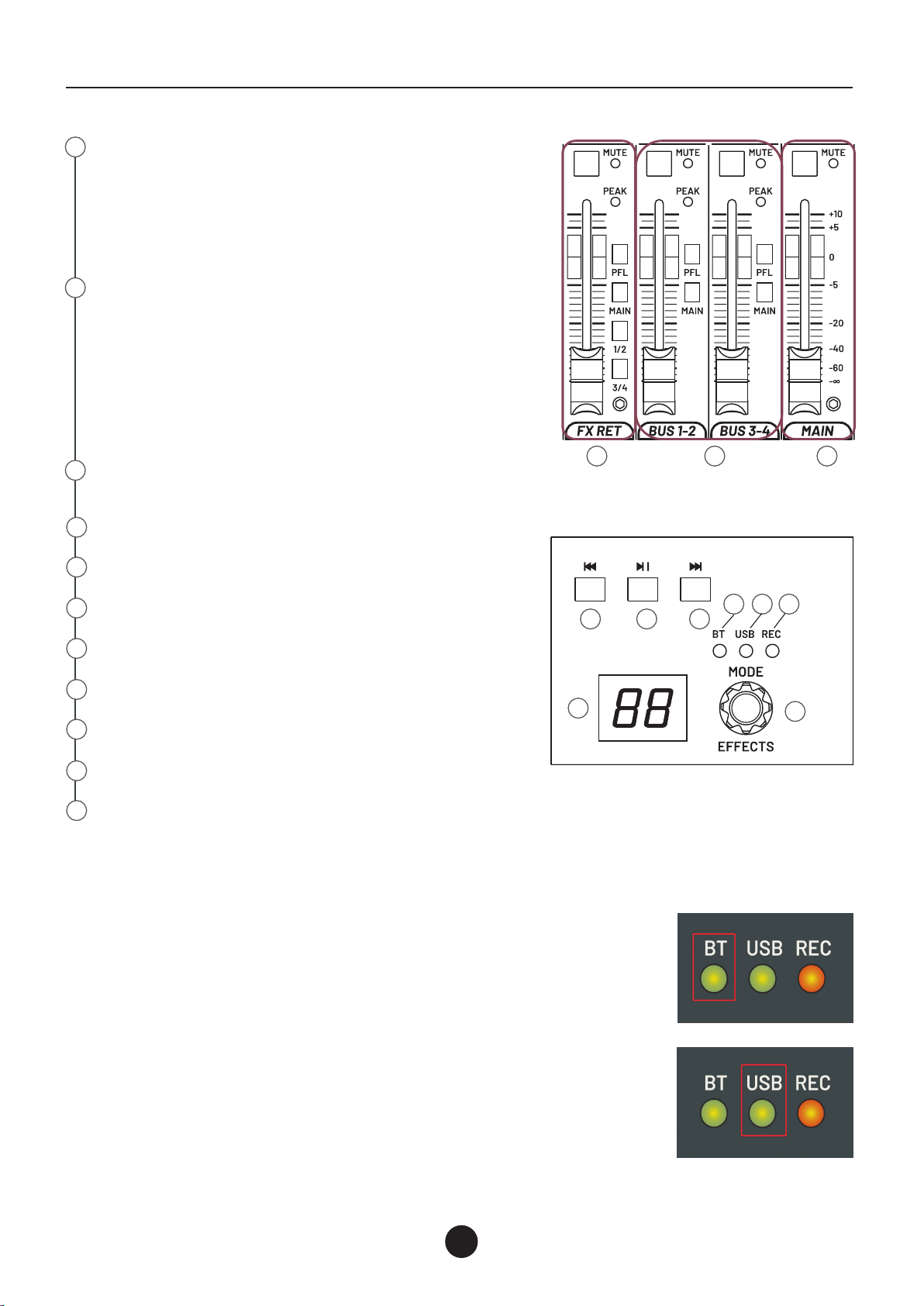
电平信号灯
这 12 个 LED 元件电平表允许控制主混音输出电平。将输出电平保
持在“CLIP”指示以下以避免信号过载这可能会导致失真。
PFL ACTIVE LED
当按下一个或多个 PFL 按钮时,此 LED 会亮起。
CTRL ROOM 音量旋钮
这是路由到 CTRL ROOM 输出 的信号电平控制。在此期间调音台
正常使用时,主通道混音信号路由到此输出;当一个或按下更多
PFL 按钮 PFL 总线信号被路由到 CTRLROOM输出和耳机输出。
耳机音量旋钮
该旋钮控制耳机输出的电平。设置耳机音量电平,请在连接和佩
戴耳机之前控制到最小 (-∞) 以避免听力 失利。
监控部分
监听部分提供两个“TO CTRL ROOM”按钮,上面按钮弹起状态监
听主扩L/R路径的音频,按下则监听BUSSES路径的音频,下面按钮
弹起状态监听BUS1/2路径的音频,按下则监听BUS3/4路径音频。
27
28
29
30
31
32
33
34
35
36
24 25
26
27
28
29
30
31
32
33
34
35
36
37 38 39
8
面板介绍
6