WEBS-MT/R Tower Installation Instructions
Copyright 2014 Talk-A-Phone Co. All rights reserved. Page 5 of 9
Talk-A-Phone Co. • 7530 North Natchez Avenue • Niles, Illinois 60714-3804
Phone 773.539.1100 • Fax 773.539.1241 • info@talkaphone.com • www.talkaphone.com
All prices and specifications are subject to change without notice.
Talk-A-Phone, Talk-A-Lert, Scream Alert and WEBS are registered trademarks of Talk-A-Phone Co.
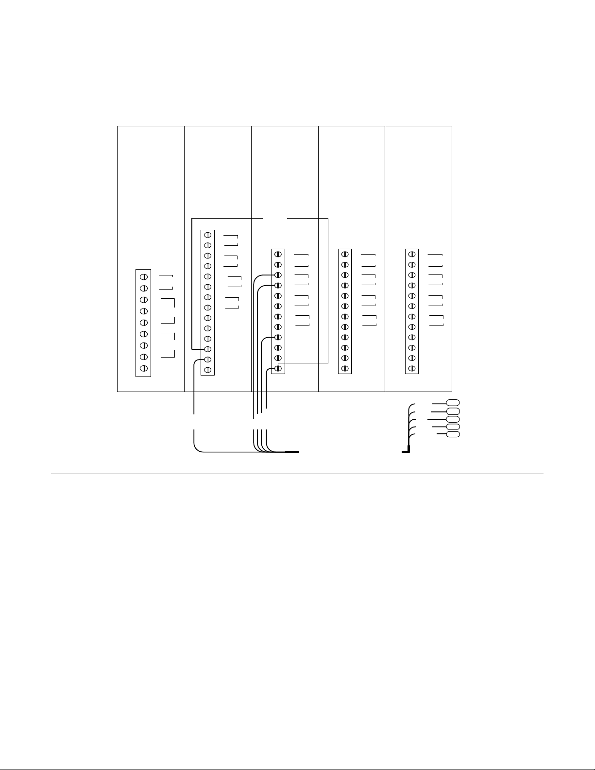
Emergency Phone AUX. Output # 2
Emergency Phone AUX. Output # 2
Emergency Phone AUX. Output # 3
Auxiliary Device Trigger Wire
Emergency Phone AUX. Output # 3
Auxiliary Device Trigger Wire
Local Paging Microphone —Audio(+)
[White]
WEBS- VCU [Microphone Input] —
Audio(+) [White]
Local Paging Microphone —Audio (-)
[Green]
WEBS- VCU [Microphone Input] —
Audio (-) [Green]
Local Paging Microphone —12 VDC Trigger
[Red]
WEBS-VCU [Microphone Input] —12
VDC Trigger [Red]
Local Paging Microphone —12 VDC Trigger
[Black]
WEBS- VCU [Microphone Input] –12
VDC Trigger [Black]
WEBS-CM-2 / VOIP-500 (AUX. Output # 1)
OR WEBS-ZPS —12 VDC Trigger [Grey]
WEBS- VCU [WEBS-CM-2 OR WEBS-
ZPS Input] —12 VDC Trigger [Green]
WEBS-CM-2 / VOIP-500 (AUX. Output # 1)
OR WEBS-ZPS —12 VDC [Grey/Black]
WEBS- VCU [WEBS-CM-2 OR WEBS-
ZPS Input] —12 VDC [White]
WEBS-CM-2 / VOIP-500 OR WEBS-ZPS —
Audio (+) [Brown]
WEBS- VCU [WEBS-CM-2 OR WEBS-
ZPS Input] —Audio (+) [Red]
WEBS-CM-2 / VOIP-500 OR WEBS-ZPS —
Audio (-) [Green]
WEBS- VCU [WEBS-CM-2 OR WEBS-
ZPS Input] —Audio (-) [Black]
WEBS-ZPS —Bare Shield [Yellow]
WEBS- VCU [WEBS-CM-2 OR WEBS-
ZPS Input] —Bare Shield [Yellow]
WEBS-CM-2 –12 VDC Power (-)
[Black]
Face Plate Light –12 VDC Power (-)
[Black]
LED Blue Light —12 VDC Power (-)
[Black]
Paging Amplifier –12 VDC Power (-)
[Black]
WEBS-VCU / Paging Amplifier Shield
Power Supply / Battery —12 VDC (-)
[Black]
WEBS-VCU –12 VDC Power (-) [Black
or Green]
Power Supply / Battery —12 VDC (+)
[Yellow]
WEBS-VCU —12 VDC Power (+) [Red
or Brown]
Paging Amplifier —12 VDC Power (+)
[Red or White]
LED Blue Light —12 VDC Power (+)
[White]
Face Plate Light —12 VDC Power (+)
[Red]
WEBS-CM-2 —12 VDC Power (+)
[Red]