TANDBERG TR-2075 User manual


2
Contents:
PowerON/OFF switch.................................................................................................. Page3
Extrapowersockets........................................................................................................ Page3
Lightdim........................................................................................................................... Page3
FMAntennas..................................................................................................................... Page4
Tuningon FM.................................................................................................................... Page6
AMAntennas..................................................................................................................... Page8
Grounding....................................................................................................................... Page8
Tuningon AM................................................................................................................... Page9
Volume-Balance .......................................................................................................... Page9
ToneControls.................................................................................................................... Page9
Stereo-mono switching..................................................................................................... Page10
UseofPREAMP OUTand MAINAMP INsockets.......................................................... Page10
Filters................................................................................................................................ Page11
Headphones...................................................................................................................... Page12
Loudspeakers.................................................................................................................. Page13
Roomacoustics............................................................................................................... Page14
Stereotips....................................................................................................................... Page14
Speakerselector.............................................................................................................. Page15
Outputpowerindicator................................................................................................... Page15
Listeningtorecords............................................................................................................ Page16
Playbackfromtaperecorders(TAPE1and TAPE2)....................................................... Page17
Recordingfromthereceiver................................................................................................ Page18
Recordingfromatranscriptionunit..................................................................................... Page19
Copyingtape................................................................................................................... Page20
Recordingonathirdtaperecorderwithorwithoutaudiocontrols...................................... Page21
Monitoringduringrecording........................................................................................... Page22
4Channeluse................................................................................................................. Page22
Simultaneousrecordingofaradio/transcriptionprogramandplaybackof
anotherprogramfromtape............................................................................................ Page23
Plugs.................................................................................................................................. Page24
Usefuldata......................................................................................................................... Page24

3
PowerON/OFF switch
Makesurethatthereceiverismarkedwiththecorrect
a.c.voltageforyoursupply.
SwitchthereceiveronbydepressingtheON/OFF-button.
Anotherpushonthebuttonwill releaseit andswitchthe
receiveroff.Thisbuttonalsocontrolsthepowertooneofthe
extrapowersocket, markedSWITCHED,atthehackofthe
receiver(moredetailsbelow).
NOTE!
Whenswitching onyou will notice thatnothinghappensuntil
about3secondsafteryou havepushedtheON/OFF button.
Thenyou will hearaclickfrominsidethecabinetand the
receiverbecomeslivesmoothlywithoutaudibleswitching
transientsinthespeakers.
Extrapowersockets
Threeextrapowersocketsareprovidedatthebackofthis
receiver.TheseextrasocketsareintendedforotherHi-Fiunits
and reduce thenumberofuntidypowercables.
Twoofthesocketsby-pass theON/OFF-buturn
and areliveassoonasthereceiverpowerplugislive.These
socketsaremarkedUNSWITCHEDand thetotalcombined
powerdrawnfromthem mustnotexceed200 W. These
socketsareusefulforconnecting Hi-Fiunitshavingtheirown
powerON/OFF switches.
ThethirdextrapowersocketismarkedSWITCHEDand is
controlledbytheON/OFF switchonthereceiver.Thissocket
issuitableforaHi-Fiunit thatdoesnothaveitsownON/OFF
powerswitchand thetotalpowerdrawnfromit mustnot
exceed100 W.
Checkthepowerconsumptionoftheunitsyou connect
totheseextrasocketstoensurethatitfallswithinthe
permissibletotalrating.
NOTE!Whenusing aswitchedwall socketrememberto
releasetheON/OFF-buttononthereceiverbeforebreakingthe
powerwiththeswitchedwall socket. Otherwiseyou will hear
aloudclickinthespeakerswhenswitchingon.
Lightdim
Ifthescaleandmeterlightsaretoo bright, depress the
LIGHTDIMbuttonontheextremerightsideofthereceiver.
Anotherpushonthisbuttonwill restorethelightstofull
brightness.
3

4
FMAntennas
Whattypeofantennadoyou need?
Yourneedforagoodantennawill depend on thereceiving
conditionswhereyou live;thefurtheryou areawayfromthe
transmitterandthemoreobstacles(hillsand tall buildingsfor
example)betweenyou and thetransmitter, thegreaterwill he
yourneedforagoodantenna. Rememberthatit isnotgood
enough justtoreceiveasignal,especiallyifyou areaserious
stereolistener. You needtoreceiveasignalthatismuch
strongerthananyunwantedelectricalnoisethatmightbe
lurking around inyourarea. Furthermore, FMsignalsbounce
off largeobstaclesand causeyou toreceivethesameprogram
fromseveraldirectionsatthesame time, possiblyoutof
phasewithoneanother.Thisgivesdistortionwhichyou do
notwant.Insteadyou needonestrong, clearsignalstraight
fromthetransmitterand thismaycall foranelaborate,
directionalantenna.
Ifindoubtyou canconsult yourdealerwhowill probablybe
morefamiliarwithlocalreceivingconditionsthanmost
people.Inanyeventyou shouldinstall anantennathatis
betterthantheonethatyou thinkyou canjustmanagewith,
becauseunderdoubtfulconditionsagoodantennaisjustas
importantasgoodloudspeakers.
Whetheryou needasimpleantennasuchasafoldeddipoleor
anelaboratemulti-elementarray, thefollowing tipswill be
useful.
Antennaconnections
Thisreceiverisequippedwithabalancedantennainputand
anunbalancedantennainput.
The300 ohmbalancedinputterminals(socketonEuropean
version)areintendedforconnectiontoa300ohmantennavia
aflattwin-leadbalancedfeederhavingthesame impedance.
The75 ohmunbalancedinputterminals(socketonEuropean
version)areintendedforconnectiontoanantennaviaa75
ohmcoaxialcable.Thecenterconductorofthecableshould
beconnectedtotheterminalmarked75 ohmsandtheshield
shouldbeconnectedtothechassisterminaljustbelow.
Ifyou havetheEuropeanversionyou shouldfit the
appropriateplug.

5
Asimplefoldeddipoleantenna
Asimplefoldeddipoleforconnectiontothebalancedinput
canbeeasilymadefromflattwin-leadwithanimpedance of
240to300ohms, A135 cm (53")piece ofantennalead
shouldbeusedfortheloop. Stripoff approximately1cm
(1/2'') ofinsulationateachendandsolderasshown. Cutone
ofthewiresinthemiddleoftheloopandconnectanother
twin-leadtoactasfeedertotheinput.Solderasshown.
Thisantennacanbeusedindoorsoroutdoors. Whenused
outdoorsthesolderjointsshouldbeprotectedagainstthe
weatherand theloopcanbefixedtoaflatwoodenboard.
Whenusedindoorstheloopcanbefixedtoanyconvenient
non-metalicstructureoraflatwoodenboard.Theimportant
requirementinall casesisthattheloopshouldbefirmly
fixed,horizontal, and straight.
Toobtaingoodreceptiontheloopshouldbeapproximately
atrightanglestothetransmitter(seediagram)although the
bestorientationmayhavetobefound experimentally.
Typicalmulti-elementantenna
Thediagram shows atypicalmulti-elementantennaforuse
wherereceivingconditionsaredoubtful. Thistypeof
antennawill providetypi-cally6dBmoregaincompared
withafoldeddipole(theantennasignalfedtothereceiver
isdoubled).
Manytypesofmulti-elementarraysareavailableand some
canevenberotatedeverytime you tuneintoadifferent
station.Yourdealerwill adviseyou oryou canbuy
specialistliteratureandbecome anexpertyourself.

6
Tuning on FM
SelectFMreception bydepressingtheFMbutton.
Theredlightoverthebutton will lighttellingyou that
thereceiverisintheFMmode.
Usethelargeknob ontherightsideofthescaleto
tuneintherequiredstation.
NOTE! MakesurethatthePREAMP REC
buttonisreleased.
Correcttuningisimportant,particularlyforstereo,if
distortion istobeavoided. Thisreceiveristhere-fore
equippedwithtwotuningmeters, oneindicatingsignal
strength(SIGNAL)and theotherindicatingmidscale
forexacttuning(TUNING). Firstadjustthetuning
knob formaximumdeflection ontheSIGNALmeter
and thenmakeafinalfineadjustmenttoobtain
midscaledeflection ontheTUNINGmeter.
Thefrequencycalibration ofthescaleisaccurateto
within±200 kHz. Sodonotbeconfusedifastation
transmittingon, forinstance, 103.9MHztunesinat
104.1MHzon thescale. Thisisstill withinthe
tolerance. Thescaleissimplyaguideandwhatreally
mattersisthatyou usethetwotuningmeterscorrectly.
Muting
Thehighamplification necessarytoobtaingood
sensitivityand limitinginhighclass tuners, makes
tuningnoisy. Toavoidthis, amutingcircuit blocksthe
receiverautomaticallywhennosignalisreceivedorif
thesignalistoweaktogivesatisfactorynoise
suppression. Toreceiveastation thatisnotstrong
enoughtocanceltheblockingeffectofthemuting
circuit, thecircuit canbeswitchedoff.
ThemutingfunctionisactivatedbydepressingtheFM
mutingknobontheextremerightsideofthefront
panel. Anotherpushon thebutton will releaseit and
cancelthemuting.

7
Stereo/mono
ThisreceiverisfullyequippedforthereceptionofFM
stereobroadcasts.
FMstereobroadcastingisbasedonthepilottonesystem
whichallows theprogram tobereceivedinmonoonmono
receiverswithoutimpairmentofprogram quality.Itisan
inherentpropertyofthissystem thatastrongersignalis
neededinstereotoobtainthesame noisesuppressionasin
mono. TheFMstereodecoderautomaticallyswitchesto
stereooperationwhenastereosignalofsufficientstrengthis
received.Ifthestereosignalfallsbelowapresetthreshold,
theprogram will beautomaticallyreproducedinmono.
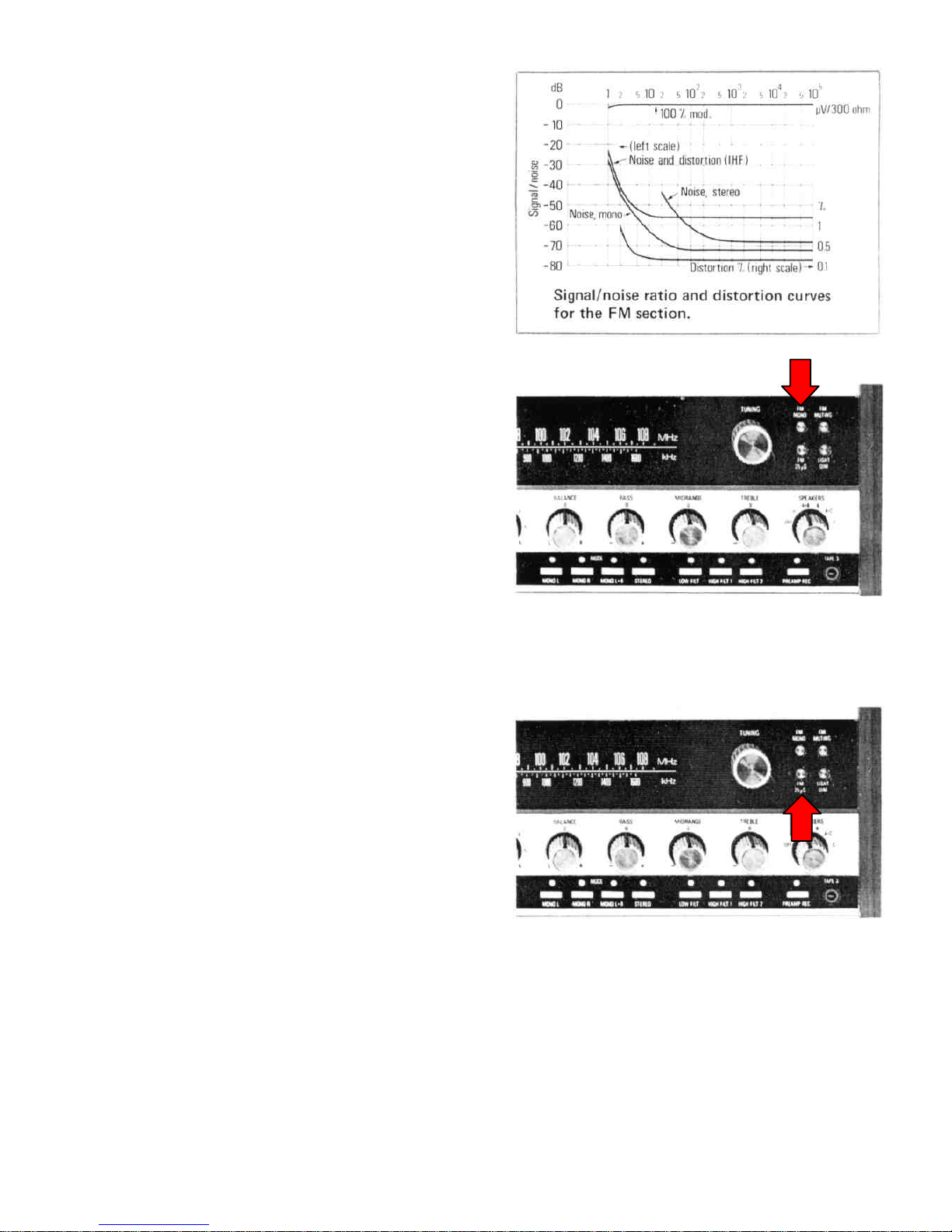
However, it ispossibleforthestrengthofastereosignalto
beadequateand yetforthesignaltobetemporarilydisturbed
bynoiseordistortion. Inthiseventdepress theFMMONO
buttonwherebytheprogram will bereproducedinmono
withoutnoiseordistortion.
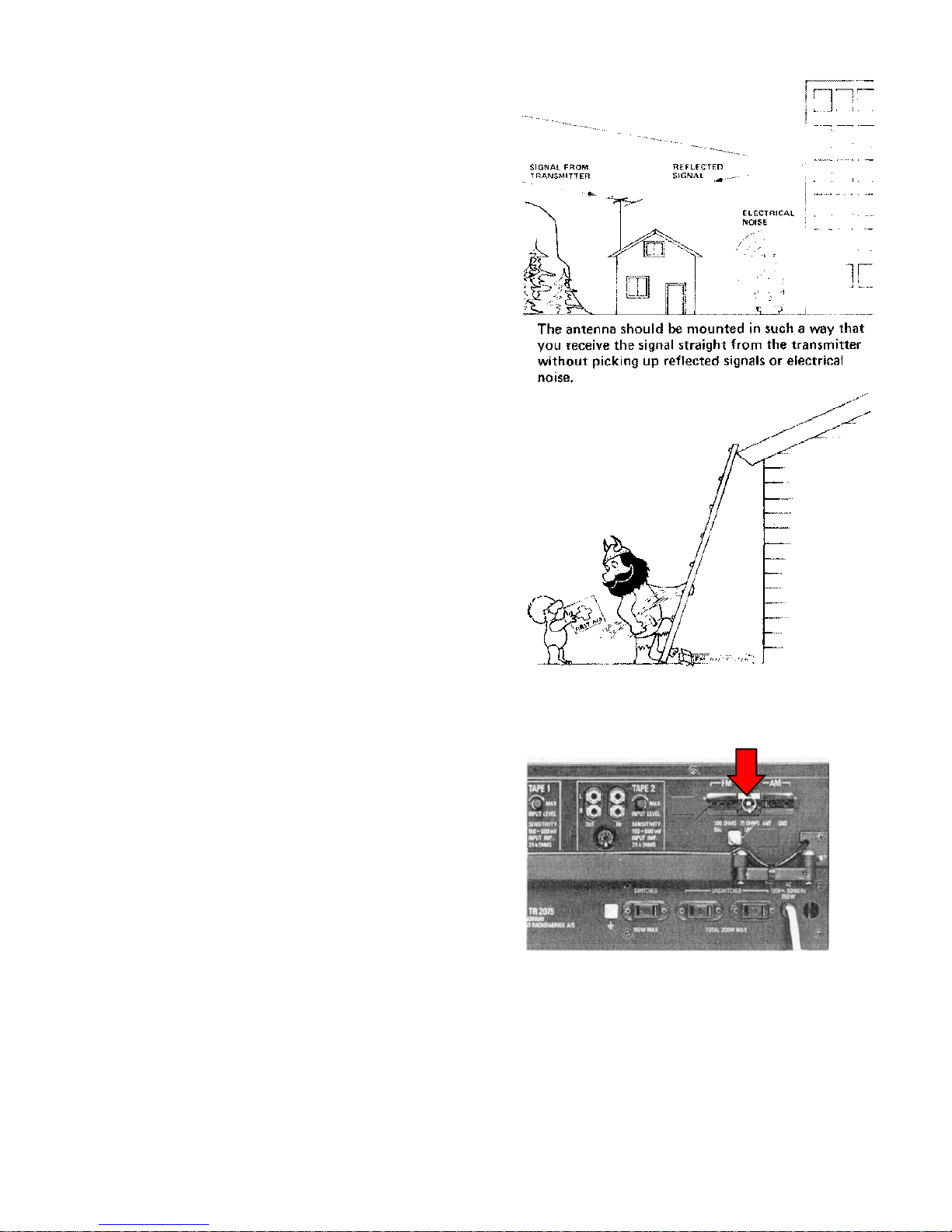
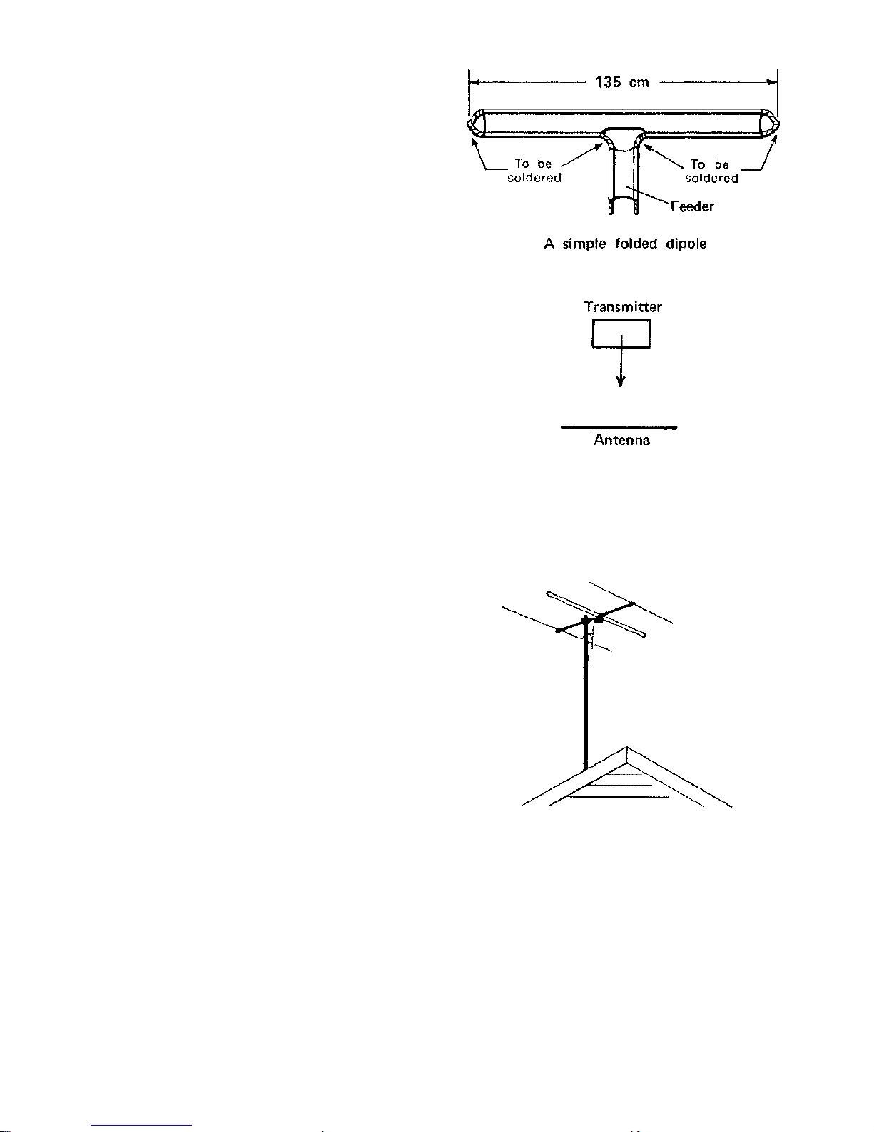
Becausestereoreceptionrequiresastrong antennasignaland
issensitivetomulti-pathdistortion, agoodantennaisneeded
particularlyunderdifficult receivingconditionsand infringe
areas. Readthepreceding sectiononFMantennas.
Dolby*programsfromFMstations
TheDolbyBnoisereductionsystem offersapossibilityto
combatthehighernoiseinFM stereotransmissions.The
system isintheUSAapprovedbyFCC** forFM
broadcasting.
TheDolbyBsystem useaprogram leveldependent
preemphasis. Athighlevelthepreemphasisis25 sec, at
lowerlevelthepreemphasisincreases.Theutilizationofthe
allowedmodulationcantherebybeimproved.The
compatibilityoftheDolbyBsystem withexistingstandards
isconsideredacceptableastheaveragepreemphasisobtained
intheDolbyBencodermatchesthestandarddeemphasis.To
takefull advantageoftheDolbyBnoisereduction, aDolby
Bdecoderunit mustbeusedand thedeemphasisnetworkin
thereceivermustbecorrectedto25 sec.
ForthosewhomayreceiveDolbyBencodedFMbroadcasts
wehavefound aswitchabledeemphasistobeauseful
feature, Thisservestwopurposes. First: Toenabletheuser
toutilize aseparateDolbydecoder, forinstance thedecoder
alreadyincorporatedinTandbergTapeRecorders3600XD,
9200X.Dand 10XD. Second;Toenableadirectre-cording
oftheDolby Bencodedprogram forlaterdecoding when
playedbackthrough thetaperecorder'sDolbycircuits.
PROCEDURE:
WhenreceivinganFMDolbytransmissionandusing a
DolbyBdecoder,theFM 25 uSbuttonmustbe
depressed.Thebuttonmustalsobe
depressedwhenadirectrecordingofaDolbyBtransmission
iswanted***.
WhenreceivinganFMDolbytransmissionwithoutusing a
DolbyBdecoder, theFM25 Sbuttonmustbereleased.
*ThenameDolbyisaregisteredtrademarkofDolby
LaboratoriesInc.
** FCC standsforFederalCommunicationsCommission, theUSA
broadcastingstandardsorganization.
***IfyouareusingaTandbergTapeRecorderwithDolby, setthe
DolbyknoboftherecordertoDOLBYFM.

8
AMAntennas
Ferrite-rod
Foroperationinthebroadcastbandthisreceiverisequipped
withamoveableferrite-rodantenna.Thisantennaisintended
forlocalreceptionwherethesignalstrengthisnormallyfairly
high,butit canunderfavorablereceivingconditionsalsopick
upmoreremotestationsefficiently.Theferrite-rodantennais
highlydirectionalandpicksupthestrongestsignalwhenit is
atrightanglestothetransmitter.Theantennaishingedand
shouldberotatedtothepositiongivingthebestreception.
Thisisalsopossiblewhenthereceiverisplacedonashelf.
Theferrite-rodantennacanneverperfectlyreplaceagood
outdoorantenna.
NOTE! Theantennacircuit isbuilt intotheferrite-rodcasing.
WhenlisteningtoAMyou shouldalwaysmovetheferrite-
rodawayfromtherearpaneltoavoidde-tuning ofthe
antennacircuit. Thisisalsoimportantwhenusing an
outdoorantenna.
Outdoorantenna
Togivethebestresultsanoutdoorantennashouldbeused.
Suspendawire15 to20 meters(50 to60feet)long atthe
highestpossibleelevation. Thebestresultsmayheobtained
byexperimentation.
ConnectafeedertotheterminalmarkedAMANT(socketon
Europeanversion)andifthefeederislong avoidrunningit
too closetowalls.
Ifyou havetheEuropeanversionconnectthe
appropriateplug.
Grounding
ToobtainbestAMreceptiongroundingofthereceiveris
recommended. ConnecttheAMground terminal(A)tothe
nearestwaterpipe.
Thegrounding terminalBisdesignedforFM
coaxialantennacable(U.S. modelonly).
Thegrounding terminalCispreparedforgroundingof
transcriptionunit orrecordplayerchassiseswhenphono
connectorsareused.
Wiring oftheDINconnectorforphonouseisshownon
thebackcover.

9
Tuning on AM
SelectAMreceptionbydepressingtheAMbutton. Thered
lightoverthebuttonwill lighttelling you thatthereceiveris
intheAMmode.Usethelargetuning knobontherightside
ofthescaletotuneintherequiredstation.Tunefor
maximumdeflectionontheSIGNALmeter.
NOTE! MakesurethatthePREAMPREC
buttonisreleased.
Volume-Balance
UsetheVOLUMEknob tocontroltheaudiopowerfedtothe
loudspeakers. UsetheBALANCEknobtocontroltherelative
outputlevelsfromthetwospeakerchannels.Atypicaluseforthe
BALANCEcontrolistocompensatefordifferencesinthe
characteristicsorthepositioning ofleftand rightspeakers.
ToneControls
Thisreceiverisequippedwiththree independenttonecontrolsfor
controlling theBASS, 'PREBLEandMIDRANGEaudio
frequencies.Theeffectsthatcanbeachievedwhenthesethree
controlsareusedmaybeseeninthegraphs.
Theknobsarethesplit typewheretheinnerpartoftheknobisfor
therightchannelandtheouterpartoftheknobisfortheleft
channel.
Tonecontrolscanbeusedtoachieveatonepicturethatispleasingto
theindividuallistener.Theycanalsobeusedtocompensateforlack
of"body"inanyparticulartoneregionwithaprogram fromany
source. Afurtherusefortonecontrolsistocompensateforspeakers
and/orroomacousticsthatdonot. givethedesiredtonepicture,
Othercontrolsaffecting thetoneresponseareLOWFILTER,HIGH
FILTER1, HIGH FILTER2
and LOUDNESS (see page11).

10
Stereo-mono switching
Stereo-monoswitching intheaudioamplifiersmaybe
performedforradio, disc, ortapeprogramsbymeansofthe
STEREO,MONO L,MONO R,andMONOL+Rmode
buttons.
STEREObuttondepressed-thetwochannelsareseparated
forstereoreproduction.
MONO Lbuttondepressed-theleftchannelprogram isfed
tobothspeakers.
MONO Rbuttondepressed-therightchannelprogram isfed
tobothspeakers.
MONO LandMONO Rbuttonssimultaneously
depressed—thetwochannelsareseparatedforstereo
reproduction, withthechannelscrossedover.Thisisatwo-
fingeredoperationbecauseyou mustpreventthefirstbutton
jumping outwhenyou depress thesecondbutton,
MONO L+Rbuttondepressed—thetwochannelsare
mixedtogetherandfedtobothspeakers(thisisnormalfull
monooperation).
Thediagramsillustratethefivepossibilities.
Use ofPREAMPOUTandMAINAMPIN
sockets
Thefoursocketsontheextreme leftofthebackpanelgive
access tothepre-amplifieroutputsand thepoweramplifier
inputs.
Thesocketsareintendedforconnectionofexternalnetworks
suchasequalizers, echoboxes,andreverberationunits.
NOTE!
FornormalusethesocketsmusthestrappedtogetherwithU
linksasshowninfigure(a).
WhenanexternalnetworkisrequiredbetweenthePREAMP
outputand theMAINAMPinput, removetheUlinksand
connectaccording tofigure(b).
ThePREAMPoutputprovidesapprox. 2voltsatless than
0.1%distortionand hasasource impedanceofapprox.
1kohms.

11
Filters
LOWFILT
Rumblefromarecordplayer,acousticfeedbackbetween
speakersand apick-up, orexcessivebassresonance ina
speakeroraroomcanall becontrolledbymeansofthe
LOWFILT.Thegraph shows theeffectofthecontrol
(-12 dB/octave).
HIGH FILT1
Iftheprogramisaccompaniedbystrong hiss orscratchnoise
fromoldand wornrecordsornoisefromataperecorderor
fromthereceiver, depresstheHIGHFILT1buttontoobtain
moderateattenuationofthehigh frequencies.Thegraph
shows theeffectofthecontrol(—12 dB/octave).
HIGH FILT2
Tinscontrolcanbeusedforthesame purposeasthe
HIGH FILT 1control, it simplygivesless attenuation
(—6dB/octave)asmaybeseeninthegraph.
HIGH FILL 1and HIGH FILT2
Depressingboththesebuttonssimultaneouslygivesthe
heaviestattenuationofall atthehighfrequenciesasmaybe
seeninthegraph(— 18dB/octave).
LOUDNESS
Atlowvolume theearisless sensitivetohighand lowtones.
Asaresult musicatlowvolume fromspeakerstendstolack
high andlowtonesandsoundsasifit hastoo much"body"
inthemiddletonerange.Tocompensateforthiseffect,
depresstheLOUDNESS buttonwherebythebassand
treblewill beboostedaccording tothesetting ofthe
VOLUMEcontrol. Thegraphshows howthisboost
increasesasthevolume isturneddown.

12
Headphones
Stereoheadphonescanheconnectedtothe3-polejacks
markedPHONESontheleftsideofthefrontpanelandthe
program levelcanbeadjustedbytheVOLUMEand
BALANCEcontrols. Twopeoplecanlistenatthesametime
iftwosetsofheadphonesarepluggedinandyou canavoid
disturbing otherpeopleintheroombyswitchingtheknob
SPEAKERStoOFF.
Headphonelisteningisveryconvenientformonitoring when
recordingsarebeing made, particularlyifmicrophonesand
loudspeakersareinthesameroombecauseit avoids
"acoustichowling".
Some peoplealsopreferheadphoneswhenlisteningto
music. Theyprovideamoreintimatelisteningexperience
and difficultiesassociatedwithroomacousticsareavoided.
Buttherearedisadvantages, forexamplethewholesound
environmentturnswiththelistenerwhenhemoveshishead,
afeelingregardedbysome peopleasunnatural. Itisamatter
ofpersonaltaste.
Headphonestodayaremainlythemoving-coil typeandare
obtainablewithimpedancesrangingfromabout8ohmsupto
about2000ohms.
Theimpedance oftheheadphonejacksis220 ohmsand they
will acceptanyheadphoneswithanyimpedance above4
ohms. However, somecautionmaybenecessarywhen
playingathigh volumes, becausesome typesofheadphones
maybedamagedbyexcessivepower.Thecurveontheright
shows howmaximumobtainablepowervarieswiththe
headphoneimpedance.
Headphonescomeinall shapes, sizes, and weightsandare
largelyamatterofpersonalpreference.Whenbuying
headphonesit iswisetotrythemonandbeawarethatthe
heavy, closefitting typemaycausefatiguewhenusedfor
long periods.
Electrostaticheadphonesmaybeusedonthisreceiver.They
arethoughtbysome peopletogivecrispersound.
Remembertoorderheadphonesterminatedina14"jack
plug. Occasionallytheplugshouldbegivenaquickrubwith
asoftclothand averysmall amountofvaseline.

13
Loudspeakers
Connections
ConnectspeakerstotheterminalsmarkedLOUDSPEAKERS
atthebackofthereceiver. Usemulti-strandedwireasthick
aspossibleand makefirmconnections.Thereceiverwill
deliveroptimumundistortedpowerwhentheresultant
impedance ofall thespeakersconnectedtoeachstereo
channelisbetween4and8ohms. Speakersorcombinations
ofspeakerswithhigherorlowerimpedanceswill giveoutput
powersbelowtheoptimum. Forloadimpedancesbelow4
ohmstheoutputpowerdropsrapidly(see curve).
Thebottomfigureshows some possiblespeaker
combinationsforonestereochannel. Eachchannelhas3
outputsinparallel,A, B,andC. Butonly2oftheoutputs
(A+BorA+C) canbeswitchedinatthesametime.Sowhen
calculating theresultantimpedanceyou musttakethisinto
account.
Polarity
Whichevercombinationofspeakersisusedit isimportantto
observethepolaritywhenspeakersareinthesameroom. In
otherwordstheconesmustmoveforwardsand backwards
together.Ifthepolarityiswrong, oneconewill bemoving
forwardswhentheotherismoving backwardsandtheresult
will beareductioninbass volume. Thepolaritywill usually
becorrectwheneachterminalmarkedwithaminussign(---)
ontherearpanelofthereceiverisconnectedtotheterminal
markedCOMMON (orNEGATIVE)oneachrespective
speaker. However, reversalsofpolaritycanoccurinthe
wiring betweenthereceiverandthespeakersoreven
occasionallyinsidethespeakercabinetandonewaytobe
certainistocheckthebass volume (undermonoconditions
withthespeakersfacing eachotherabout6inchesapart)and
reverseanywrong connections.
Whattypeofspeaker?
Thisreceiverhasbeendesignedforusewithspeakershaving
awiderangeofphaseanglesi.e. electrostaticaswell as
moving-coil systems.Agoodall-round typeofloudspeaker
whichisreliableindesign, manufacture, anduseisthetotally
enclosedinfinitebaffletype.Tandbergproduce afull range
ofthistypeofloudspeaker. Askyourdealerfordetails.

14
CombinationsofA, B, and C
Eachstereochannelhasthreesetsofoutputterminals,A,B,
and C.Onewayofusing theseoutputsistogrouptwo(A+B
orA+C) speakerstogetherforeachstereochannel.Ifthe
speakersforeachchannelareseparatedbyaboutthree feet
thiswill giveabroaderfronttothestereoeffect.Thebottom
figureshows theset-up.
Anotherwayofusing theoutputsisfortheAspeakerstobe
inoneroom, theBspeakersinasecondroomand theC
speakersinathirdroom.Thispermitsfull stereooperation
intwooutofthree oftheroomssimultaneously,asshownin
thefigure.
Whereshouldthespeakersbeplaced?
Thebestpositionforspeakersinaroomdependsuponthe
roomacousticsand thetype(ortypes)ofspeakersyou use.
Fourbasicarrangementareshownintheadjacentfigures.It
isparticularlyinthebassregionwhereyou arelikelyto
havetoo muchortoolittleoranunevensound picture.
Roomacoustics
Loudspeakersaredesignedtoprovideasound picture
judgedtobecorrectinan"average"positioninan"average"
room. However, notworoomsand notwospeakersarealike
soit paystoconsidertheshape,size,structure, and
furnishingsofaroomwhenit comestobuying andsiting
loudspeakers.
You usuallycannotdomuchabouttheshapeandsizeofa
roomexceptpossiblybyusing acousticscreenstomakeit
non-symmetrical. AsFaraspossiblethefloor, ceiling and
wallsshouldnotbetoo hard.Thickcurtains, carpets,soft
furniture, softwoodenpanelsandacoustictilesall helpto
reduce excessivereflections.
Stereotips
Thefollowing tipsmayhelpyou withyourstereo
setup.
1. Place thespeakersatthesameheightand(asfaras
possible)onthesame levelasthelistener'sears.
2. Keepthespace betweenthelistenerand thespeakers
clear.
3. Arrangetheacousticstructuresand surfacesintheroom
adjacenttothespeakerstobethesameforbothspeakers.
Conventionalsitingofamoving-
coil speakersystem inacornerof
aroom toobtainmaximumbass
responseandevenexcitationof
room modes.
Alternative siting ofaspeaker
awayfrom walls. Thismayreduce
excessivebass responseorgive
optimumcouplingforan
electrostaticspeaker.
Using(A+B)or(A+C)parallel
speakeroutputstoobtaina
broaderstereofront.
ConventionaIsiting oftwospeakers in
astereosystem. Thedistance
betweenthespeakers
shouldbeabout2/3thedistance
tothelistener. Thespeakers maybe
angledinwardswith
advantage.

15
4. Arrangethespeakerssothatthedistance betweenthem is
about2/3thedistancetothelistener.Too littledistance
betweenthespeakersisbetterthantoo much.
5. Whenlisteningtoamonospeechprogram switchoverto
onespeakerbyusingtheBALANCEcontrol
Speakerselector
ThespeakerselectorswitchmarkedSPEAKERShassix
positionsasfollows:
OFF: All speakersdisconnected
A: Program tospeakeroutputsAonly
A+B: Program tospeakeroutputsAand Bonly
B: Program tospeakeroutputsBonly
A+C: Program tospeakeroutputsAand Conly
C: Program tospeakeroutputsConly
Inall positionsofthespeakerselectortheprogramisalsofed
tothePHONESoutputs.
NOTE!
Itisnotpossibletofeedall threespeakeroutputsatthesame
time.
Outputpowerindicator
Depress thebuttonPOWERREADINGonthe
lowerleftofthefrontpaneltoobtainanindicationonthe
SIGNALmeteroftheaudiopowerbeingdeliveredtothe
speakers.
Themeterispeakreading, andindicatesoutputvoltagefor
theleftorrightchannel, whichevermomentarilyhasthe
highestoutput. Maximumobtainableoutputpowerdepends
onthespeakerimpedance (loadperchannel).Thetableshows
therelationbetweenoutputpowerand meterreadingat
differentloadimpedances.
Theoutputmonitoring functionofthemeterservestwo
purposes:
—Toavoidoverloadingtheoutputamplifier,
—Toavoidoverloadingspeakersnotratedforthefull output
poweroftheamplifier,
NOTE:
Ifthereceiverisoverloadedattoo high ambienttemperature
(insufficientventilation), athermalswitchwill disconnectthe
amplifier.Theamplifierwill, however, resume normal
operationassoonasthetemperatureinsidethereceiverhas
droppedsufficiently.
MeterreadingLoad 10 12-5 15 17-5 20 25
4ohm 25W 40W 56W 76 W 100W
156W
8ohm 12W 20W 28W 38W 50W 78W
16 ohm 6W 10W 14W 19W 25W 39W

16
Listeningtorecords
Atthebackofthereceivertherearetwosetsofphonoand
DINinputsockets(markedPHONO 1and PHONO 2)for
twotranscriptionunitsortworecordplayers, Eachinputhas
animpedance of47 kohmsand hasthecorrectsensitivityfor
magneticpick-ups.
Onetranscriptionunit
Toplayrecordsfromonetranscriptionunit, connectthe
transcriptionunit tothePHONO 1socket(using either
phonoorDINplugs), startthetranscriptionunit anddepress
thePHONO 1buttononthefrontpanel.
Twotranscriptionunits
Using twotranscriptionunitsisparticularlyconvenientwhen
you areplayinglargeorchestralorchoralworksspanning
severalrecords. You canthenplayonerecordaftertheother
non-stop. Thisgivesyou facilitiessimilartothoseonarecord
player.
PROCEDURE.
ConnectthetwotranscriptionunitstothePHONO 1and
PHONO 2sockets, startthePHONO 1transcriptionunit and
depressthePHONO 1buttononthefrontpanel.As therecord
ends,startthePHONO 2transcriptionunit and depress the
PHONO 2button. Withpractice you will achievetiming
whichmakesit possibletoplaytworecordswithoutloss of
continuity.
Ofcourseyou canthenputathirdrecordonthefirst
transcriptionunit and playthatwithoutloss ofcontinuity
and soon.
You canalsohavebothtranscriptionunitsplayingatthesame
time andswitchbackwardsandforwardsbetweentworecords
byalternatelydepressing thePHONO 1buttonandthe
PHONO 2button.
Inputsensitivity
Whenswitching fromoneprogram source toanothertheoutput
shouldnotchange.Toobtainthisyou will needtoset: theinput
sensitivitycontrolsasfollows.
Depress theFMbuttonand tuneinastrong FMstation. Then
switchovertoaprogramfromPHONO 1bydepressing the
PHONO 1button, andadjustthePHONO 1sensitivitycontrol
toobtainthesame outputasfortheFMprogram. The
adjustmentrangeforthePHONO 1inputis2.2to10 mV.
ThesensitivityofthePHONO 2inputisfixedat3mV
and cannotbeadjusted.
AdjusttheTAPE1andTAPE2sensitivitycontrolsinthesame
manner, oneaftertheother,whileyou listentoprogramsfrom
therespectivetaperecorders.Theadjustmentrangeofthe
TAPEinputsis150 to600 mV,
NOTE!
DepressingeitherofthePHONO buttonsautomatically
disconnectsanyradioprogramthatispresent(butnotatape
program becausetapeprogramshavepreference).
Thereceiverhasauniqueswitchingsystemthatprovides
smoothtransitionswhenyou switchfromoneprogramsource
toanother.

17
Playback fromtaperecorders(TAPE 1,TAPE 2and TAPE3)
Atthebackofthereceivertherearetwosetsofphonoand
DINinput, sockets(markedTAPE1andTAPE2)fortwo
taperecorders.Tworeel-to-reelmachinesortwocassette
machinesoroneofeachtypecanbeconnected. Eachinput
hasanimpedance of25 kohmswhichissuitableformost
moderntaperecorders.
Onetaperecorder
Toplaytapesfromonetaperecorder, connectthe
taperecordertotheTAPE1socket(using either
phonoorDINplugs), startthetaperecorderand
depresstheTAPEMON1buttononthefront
panel.
Twotaperecorders
Toplaytapesfromtwotaperecorders(oneata
time), connectthetwotaperecorderstotheTAPE
1and TAPE2sockets. Toplayatapefromthe
TAPE1machine, depresstheTAPEMON 1button
and startthetaperecorder.
ToplayatapefromtheTAPE2machine, release
theTAPE1buttonand depress theTAPE2button
and startthetaperecorder.
PlaybackfromTAPE3
ConnectataperecordertotheTAPE3jack. Depress the
PREAMP. REC. button. Thesignalwill thenbefeddirectly
tothepoweramplifier, and consequentlythevolume,
balanceand tonecontrolswill havenoinfluenceonthe
program being playedback.
SettheVOLUMEcontroltotheminimumposition,
otherwiseotherprogramsfromradio, transcriptionunitsor
othertapeswill mixwiththesignalfromthetaperecorder
connectedtoTAPE3jack.
Inputsensitivity
ThesensitivityofTAPE1inputandTAPE2inputcanbe
adjustedtobebetween150 mVand 600 mV
bymeansofindependentpotentiometersadjacenttothe
sockets. See page16.
NOTE!
DepressingeitheroftheTAPEMON.buttonsautomatically
disconnectsanyrecordorradioprogramthatispresent.
Furthermore, TAPEMON. 1alwaystakesprecedenceover
TAPEMON. 2whenboththesebuttonsaredepressed
simultaneously.
Thereceiverhasauniqueswitchingsystemthatprovides
smoothtransitionswhenyou switchfromoneprogramsource
toanother.
WARNING!
DepressingthePREAMPRECbuttonreducesthe
amplificationby30 dB.Thereforebecarefulnottoreleasethe
buttonwhenplayingathigh volume. Otherwiseyou may
damageyourspeakers.

18
Recording fromthereceiver
ConnectoneortwotaperecorderstoTAPE1inputand/or
TAPE2input(orboth)atthehackofthereceiver. Use
phonoorDINplugs. Depress eithertheFM buttonorthe
AMbuttonandtunethereceiverasdescribedonpage6or
page9. Anyradioprogram thatisbeing reproducedinthe
speakers(orheadphones)will nowbefedviathesockets
markedOUTtothetaperecorderandrecorded.The
VOLUME,BALANCE, BASS, MID-RANGE,TREBLE,
LOUDNESSAND FILTERcontrolswill havenoeffecton
therecording.Therecordedprogram will befedbacktothe
receiverviathesocketsmarkedINwhereit will beavailable
foraB-testifrequired. (See Monitoring during recordingon
page22).
Torecordaprogram onathirdtaperecorderwithorwithout
beingaffectedbyall theaudiocontrols,
see page21.
Tapetips
Thetwomostimportantcharacteristicsofatapeare
signal/noiseratioand frequencyrange.Thesignal/noiseratio
isdeterminedbytwoquantities—thesigned, thatistosay
theloudestundistortedsound thatcanberecordedonthe
tape(whichshouldbeasloudaspossible)andtheinherent
hissing noiseonthetape.Thesetwoquantitiesaredistinct
separatepropertiesofthetape.Takentogethertheydecide
thedynamicrangeofthemusicthatcanberecordedwithout
distortion. Inotherwords, thehigherthesignal/noiseratioof
thetapethehigherthedynamicrangeofthemusicthatcan
berecorded.
Tapeswithahighsignal/noiseratioareknownas"Low
Noise/High Output'' tapesand theyaregraduallyreplacing
oldertapeswhichhaveinferiorsignal/ noiseratios. Although
oldertapescanbeplayedonanytaperecorderit shouldbe
notedthattheywill giveaninferiorrecording performanceon
taperecordersadjustedforLowNoise/High Outputtape.Ina
nutshell, thebestresultswill beobtainedwithLow
Noise/High Outputtaperecordedonarecorderwhichis
speciallyadjustedforit.
PLAYINGTIMEINMINUTES
Tape
[Length 71/2ips 33/4ips17/8ips15/16 ips
150' 3,75 7,5 15 30
210' 5.5 11 22 45
300' 7,5 15 30 60
450' 11 22 45 90
600' 15 30 60 120
900' 22 45 90 180
1200' 30 60 120 240
1800' 45 90 180 360
2400' 60 120
240
480
480
3600' 90 180 360 720
4200' 107.5 215 430 860

19
Recording fromatranscription unit
Connectatranscriptionunit (orrecordplayer) tothe
PHONO 1socketand ataperecordertotheTAPE1socket
atthehackofthereceiver. Putthetaperecorderintothe
RECORDmodebutdonotstartit. Startthetranscriptionunit
and depress thePHONO 1button, Lettherecordrunfora
minuteortwoand notetheindicationonthetaperecorder
inputlevelmeter. Adjusttheinputlevelcontrolsonthetape
recordertotakeaccountofanypeaksintheoutputfromthe
record. Stopthetranscriptionunit.
Nowyou canstarttheproperrecording.Startthe
transcriptionunit and thetaperecorder.Therecording will
beunaffectedbyall theotheraudio
controls. See page22 foradviceonmonitoring.
Twotranscriptionunits
Asecondtranscriptionunit canbeconnectedtothe
PHONO 2socketsothatwhentherecordon(thefirst
transcriptionunit comestoanend asecond recordcanbe
recordedwithoutstopping thetaperecorder,provided
thatyou knowtherearenooutputpeaksonthesecond
recordgreaterthanthoseonthefirstrecord.
PROCEDURE.
Asthefirstrecordends, startthesecondtranscription
unit and depressPHONO 2button.
Twotaperecorders
Asecond taperecordercanbeconnectedtotheTAPE2socket
and recording cantakeplaceonthismachineatthesametime.
Thetrialanderrorprocedureforachievingthecorrectsetting
ofthelevelcontrolscanbecarriedoutforthetwotape
recordersalsoatthesame time.See page22 foradvice on
monitoring.
WARNING!
DepressingthePREAMPRECbuttonreducesthe
amplificationby30 dB.Thereforebecarefulnottoreleasethe
buttonwhenplayingathigh volume. Otherwiseyou may
damageyourspeakers.

20
Copying tape
Twotaperecordersinvolved
a)Copying fromTAPE1toTAPE2orvice versa.
ConnectonetaperecordertotheTAPE1socketand
anothertaperecordertotheTAPE2socket.Tocopyfrom
theTAPE1machinetotheTAPE2
machinedepresstheTAPECOPY1→2button.
TocopyfromtheTAPE2machinetotheTAPE1machine
depresstheTAPECOPY2→1button.
PROCEDURE.
Startthetwomachinesandcontroltherecordinglevelon
themachinesettoRECORD. Atrialrunmaybenecessary
toavoidpeakdistortion. See page22 foradvice on
monitoring.
NOTE!
You havethegreatadvantagethatcopyingfromonetape
recordertotheothercantakeplacewhileyou listentoa
program selectedwitheitherofthebuttonsFM, AM,
PHONO 1, PHONO 2.
b)Copying from TAPE1orTAPE2toTAPE 3.
ConnectataperecordertotheTAPE1socketortheTAPE
2socket. Tocopy,depress theappropriateTAPEMON.
buttonand followtheproceduredescribedonpage21.
Three taperecordersinvolved
a)Copying fromTAPE1toTAPE2&TAPE3.
ConnectonetaperecordertoeachoftheTAPEsocketsand
onetotheTAPE3jack.Depressthe
TAPEMON. 1buttonandtheTAPECOPY1->2button. If
you nowstartall themachines,you will copyfromTAPE1to
TAPE2& TAPE3withouttoneandvolume controls. Atthe
same time you canlistentotheprogram through thespeakers.
BydepressingthePREAMP. REC.buttonyou cancopyfrom
TAPE1toTAPE2withouttoneandvolume controls, and
fromTAPE1toTAPE3withtoneandvolume controls.
b)Copying fromTAPE2toTAPEI&TAPE3.
Connectthetaperecordersasfora). Depress theTAPEMON.
2buttonand theTAPECOPY2-->button. Startthe
machines, and you will copyfromTAPE2toTAPE1&
TAPE3withouttoneand volume controls, etc. asfora).
(InterchangeTAPE1&TAPE2).
WARNING!
DepressingthePREAMPRECbuttonreducesthe
amplificationby30 dB.Thereforebecarefulnottoreleasethe
buttonwhenplayingathigh volume. Otherwiseyou may
damageyourspeakers.
Table of contents
Other TANDBERG Stereo Receiver manuals