Taylor-Wharton MicroBulk MB-450 User manual

MB - 450
Installation and Operation Manual
Do not attempt to use or maintain these units until you read and understand these instructions. Refer
to the Taylor Wharton’s “Safety First” booklet (TW - 202) for handling cryogenic material. Do not permit
untrained persons to use or maintain this equipment. If you do not understand these instructions, contact
your supplier for additional information. www.taylorwharton.com
MicroBulk
BT- 434 REV.A

BT- 434 Rev.A
2
WARNING . . . . . . . . . . . . . . . . . . . . . . . . . . . . . . . . . . . . . . . . . . . . . . . . . . . . . . . .3
Safety Precautions for Liquid Oxygen . . . . . . . . . . . . . . . . . . . . . . . . . . . . . . . . . . . . . .3
Safety Precautions for Liquid Nitrogen . . . . . . . . . . . . . . . . . . . . . . . . . . . . . . . . . . . . . .4
INTRODUCTION . . . . . . . . . . . . . . . . . . . . . . . . . . . . . . . . . . . . . . . . . . . . . . . . . . . .6
System Description. . . . . . . . . . . . . . . . . . . . . . . . . . . . . . . . . . . . . . . . . . . . . . . . . .6
Specication. . . . . . . . . . . . . . . . . . . . . . . . . . . . . . . . . . . . . . . . . . . . . . . . . . . . . .7
PIPING CIRCUITS. . . . . . . . . . . . . . . . . . . . . . . . . . . . . . . . . . . . . . . . . . . . . . . . . . . .8
P&ID: MB-450 Standard Conguration . . . . . . . . . . . . . . . . . . . . . . . . . . . . . . . . . . . . . .8
Fill and Vent Circuits . . . . . . . . . . . . . . . . . . . . . . . . . . . . . . . . . . . . . . . . . . . . . . . . .9
Express Fill Circuit . . . . . . . . . . . . . . . . . . . . . . . . . . . . . . . . . . . . . . . . . . . . . . . . . 10
Pressure Building Circuit . . . . . . . . . . . . . . . . . . . . . . . . . . . . . . . . . . . . . . . . . . . . . 11
Gas Withdrawal Circuit . . . . . . . . . . . . . . . . . . . . . . . . . . . . . . . . . . . . . . . . . . . . . . 12
Economizer Circuit . . . . . . . . . . . . . . . . . . . . . . . . . . . . . . . . . . . . . . . . . . . . . . . . . 13
Safety Devices. . . . . . . . . . . . . . . . . . . . . . . . . . . . . . . . . . . . . . . . . . . . . . . . . . . . 14
Instrumentation Circuits . . . . . . . . . . . . . . . . . . . . . . . . . . . . . . . . . . . . . . . . . . . . . 15
OPERATION . . . . . . . . . . . . . . . . . . . . . . . . . . . . . . . . . . . . . . . . . . . . . . . . . . . . . . 16
Receiving Inspection . . . . . . . . . . . . . . . . . . . . . . . . . . . . . . . . . . . . . . . . . . . . . . . . 16
Handling . . . . . . . . . . . . . . . . . . . . . . . . . . . . . . . . . . . . . . . . . . . . . . . . . . . . . . . 16
Customer Installed Equipment/Piping . . . . . . . . . . . . . . . . . . . . . . . . . . . . . . . . . . . . . 16
Filling by Pressure Transfer . . . . . . . . . . . . . . . . . . . . . . . . . . . . . . . . . . . . . . . . . . . . 16
Filling by Pump Transfer. . . . . . . . . . . . . . . . . . . . . . . . . . . . . . . . . . . . . . . . . . . . . . 17
Filling for Road Transport. . . . . . . . . . . . . . . . . . . . . . . . . . . . . . . . . . . . . . . . . . . . . 17
Withdrawing Gas . . . . . . . . . . . . . . . . . . . . . . . . . . . . . . . . . . . . . . . . . . . . . . . . . . 17
Withdrawing Liquid . . . . . . . . . . . . . . . . . . . . . . . . . . . . . . . . . . . . . . . . . . . . . . . . 18
Changing Gas Service . . . . . . . . . . . . . . . . . . . . . . . . . . . . . . . . . . . . . . . . . . . . . . . 18
MAINTENANCE. . . . . . . . . . . . . . . . . . . . . . . . . . . . . . . . . . . . . . . . . . . . . . . . . . . . 19
Leak Test . . . . . . . . . . . . . . . . . . . . . . . . . . . . . . . . . . . . . . . . . . . . . . . . . . . . . . . 19
Globe Valves . . . . . . . . . . . . . . . . . . . . . . . . . . . . . . . . . . . . . . . . . . . . . . . . . . . . . 19
Regulator . . . . . . . . . . . . . . . . . . . . . . . . . . . . . . . . . . . . . . . . . . . . . . . . . . . . . . 19
Instruments . . . . . . . . . . . . . . . . . . . . . . . . . . . . . . . . . . . . . . . . . . . . . . . . . . . . . 21
Checking Vacuum. . . . . . . . . . . . . . . . . . . . . . . . . . . . . . . . . . . . . . . . . . . . . . . . . . 21
Trouble-Remedy Guide . . . . . . . . . . . . . . . . . . . . . . . . . . . . . . . . . . . . . . . . . . . . . . 23
Replacement Parts . . . . . . . . . . . . . . . . . . . . . . . . . . . . . . . . . . . . . . . . . . . . . . . . .24
APPENDIXES . . . . . . . . . . . . . . . . . . . . . . . . . . . . . . . . . . . . . . . . . . . . . . . . . . . . . 25
Appendix 1 – MB - 450 General Arrangement . . . . . . . . . . . . . . . . . . . . . . . . . . . . . . . . . 25
TABLE OF CONTENTS

BT- 434 Rev.A
3
WARNING
The following safety precautions are for your protection. Before installing, operating, or maintain-
ing this unit read and follow all safety precautions in this section and in the reference publications.
Failure to observe all safety precautions can result in property damage, personal injury, or possibly
death. It is the responsibility of the purchaser of this equipment to adequately warn the user of
the precautions and safe practices for the use of this equipment and the cryogenic uid stored in it.
CAUTION: When installing eld-fabricated piping, it is recommended to make certain a suitable safe-
ty valve is installed in each section of piping between shut-o valves.
For more detailed information concerning safety precautions and safe practices to be observed
when handling cryogenic liquids consult CGA pamphlet P-12 “Handling Cryogenic Liquids” avail-
able from the Compressed Gas Association, 1235 Jeerson Davis Highway, Arlington, VA 22202.
Safety Precautions for Liquid Oxygen
Oxygen is a colorless, odorless, and tasteless gas that can be condensed into a liquid at the low
temperature of 297 degrees below zero Fahrenheit (-183�C) under normal atmospheric pres-
sure. Approximately one-fth of normal air is oxygen. As a liquid, oxygen is pale blue in color. Ox-
ygen is non-ammable; however it vigorously accelerates the burning of combustible materials.
Keep Combustibles Away from oxygen and eliminate ignition sourc-
es. Many substances that do not normally burn in air require only a slight spark or
moderate heat to set them aame in the presence of concentrated oxygen. Oth-
er sub stances, which are only moderately combustible in air, can burn violently
when a high percentage of oxygen is present.
Do not permit smoking or open ame in any area where liquid oxygen is stored,
handled, or used. Keep all organic materials and other ammable substances
away from possible contact with liquid oxygen. Some of the materials that can
react violently with oxygen are oil, grease, kerosene, cloth, wood, paint, tar, and
dirt that contains oil or grease. Under certain conditions ammable materials that
have become permeated with liquid oxygen are impact sensitive and can detonate
if subjected to shock.
Keep Area and Exterior Surfaces Clean to Prevent Ignition
As normal industrial soot and dirt can constitute a combustion hazard, all equip-
ment surfaces must be kept very clean. Do not place oxygen equipment on as-
phalt surfaces, or allow grease or oil deposits to remain on benches or concrete
surfaces in the vicinity of the oxygen equipment. Use cleaning agents, which will
not leave organic deposits, on the cleaned surfaces. Equipment to be used in con-
tact with liquid oxygen should be handled only with clean gloves or hands washed
clean of oil.
Maintain Adequate Ventilation
Enclosed areas containing oxygen equipment should be ventilated to prevent ac-
cumulations of oxygen and thereby minimize combustion hazards.
BT- 434 Rev.A
4
WARNING
Extreme Cold - Cover Eyes and Exposed Skin
Accidental contact of liquid oxygen or cold issuing gas with the skin or eyes may
cause a freezing injury similar to frostbite. Handle the liquid so that it won’t
splash or spill. Protect your eyes and cover the skin where the possibility of
contact with the liquid, cold pipes and equipment, or the cold gas exists. Safe-
ty goggles or a face shield should be worn if liquid ejection or splashing may
occur or cold gas may issue forcefully from equipment. Clean, insulated gloves
that can be easily removed and long sleeves are recommended for arm protec-
tion. Cuess trousers should be worn outside boots or over the shoes to shed
spilled liquid. If clothing should be splashed with liquid oxygen or otherwise
saturated with the gas, air out the clothing immediately, removing it if possible.
Such clothing will be highly ammable and easily ignited while the concentrat-
ed oxygen remains, and should not be considered safe for at least 30 minutes.
Replacement Parts Must be Suitable for Oxygen Service
Many materials, especially some non-metallic gaskets and seals, constitute a
combustion hazard when in oxygen service, although they may be acceptable for
use with other cryogenic liquids. Make no substitutions for recommended spare
parts. Also, be sure all replacement parts are thoroughly “Cleaned For Oxygen
Service” in accordance with Compressed Gas Association (CGA) Pamphlet G-4.1
“Cleaning for Oxygen Service” or equivalent industrial cleaning specications.
Observe Safety Codes When Locating Oxygen Equipment
Before locating oxygen equipment, become thoroughly familiar with National
Fire Protection Association (NFPA) Standard No. 50, “Bulk Oxygen Systems”,
and with all federal, state and local safety codes. The NFPA Standard covers
the general principles recommended for the installation of bulk oxygen sys-
tems on industrial and institutional consumer premises.
Safety Precautions for Liquid Nitrogen
Extreme Cold - Cover Eyes and Exposed Skin
Accidental contact of liquid nitrogen or cold issuing gas with the skin or eyes
may cause a freezing injury similar to frostbite. Handle the liquid so that it won’t
splash or spill. Protect your eyes and cover the skin where the possibility of con-
tact with the liquid, cold pipes and equipment, or the cold gas exists. Safety gog-
gles or a face shield should be worn if liquid ejection or splashing can occur or
cold gas can issue forcefully from equipment. Insulated gloves that can be easily
removed and long sleeves are recommended for arm protection. Trousers with-
out cus should be worn outside boots or over the shoes to shed spilled liquid.
Nitrogen is an inert, colorless, odorless, and tasteless gas making up four-fths of the air you
breathe. Liquid nitrogen is obtained by cooling air until it becomes a liquid and then removing
the oxygen. Air is roughly one-fth oxygen. Liquid nitrogen is at a temperature of -320�F (-196�C)
under normal atmospheric pressure.
BT- 434 Rev.A
5
WARNING
Keep Equipment Area Well Ventilated
Although nitrogen is non-toxic and non-ammable, it can cause asphyxiation in
a conned area without adequate ventilation. Any atmosphere not containing
enough oxygen for breathing can cause dizziness, unconsciousness, or even death.
Nitrogen, a colorless, odorless, and tasteless gas, cannot be detected by the human
senses and will be inhaled normally. Without adequate ventilation, the expanding
nitrogen will displace the normal air resulting in a non-life-supporting atmosphere.
Dispose of Waste Liquid Nitrogen Safely
Dispose of waste liquid nitrogen out-of-doors where its cold temperature cannot
damage oors or driveways and where it will evaporate rapidly. An outdoor pit
lled with clean sand or gravel will evaporate liquid nitrogen safely and quickly.
NOTE: Argon is an inert gas whose physical properties are very similar to those of
nitrogen. For handling of liquid argon, follow the safe practices described for the
handling and use of liquid nitrogen.

BT- 434 Rev.A
6
INTRODUCTION
This manual provides information for the operation and maintenance of Taylor-Wharton’s line of MB-
450 cryogenic gas supply systems. These products store cryogenic liquid and dispense it as a warm
pressurized gas. The MB-450 is designed for applications requiring nitrogen, argon, or oxygen gas.
These products are ideal for on-site lling with Taylor-Wharton’s Express cryogenic liquid delivery ve-
hicle.
Additional product specications, ow diagram, views, and important dimensions are shown on the
general arrangement drawing provided in the appendix of this manual.
System Description
The MB-450 consists of a cryogenic liquid vessel, piping, internal vaporizer, and an internal pressure
builder.
The system vessel has an approximate gross capacity of 450 liters. The vessel consists of a pressure
vessel suspended inside a jacket. The space between the pressure vessel and the jacket is evacuated
and insulated with a micro-berglass / aluminum foil radiation shield. Both the inner pressure vessel
and vacuum jacket are constructed of type 304 stainless steel. Models are available designed and con-
structed in accordance with DOT-4L or ASME Section VIII. The DOT-4L vessels may be legally transport-
ed by truck in the United States while containing product.
Piping circuits allow the vessel to vent, ll, pressurize, and provide pressurized gas. Piping is type-304
stainless steel. Valves are brass. Fittings are machined from forged brass.
Instrumentation consists of a pressure gauge and a dierential pressure gauge. The pressure gauge
allows the vessel pressure to be monitored. Accurate measurement of the vessel contents is provided
by the dierential pressure gauge. The dierential pressure gauge instrument lines are constructed of
copper tube.
The MB-450 automatically maintains pressure by vaporizing cryogenic liquid in a controlled fashion. All
energy for building pressure and vaporizing liquid is provided by heat from ambient air. The vaporizer
and pressure builder coils are attached to the inside surface of the outer jacket.
BT- 434 Rev.A
7
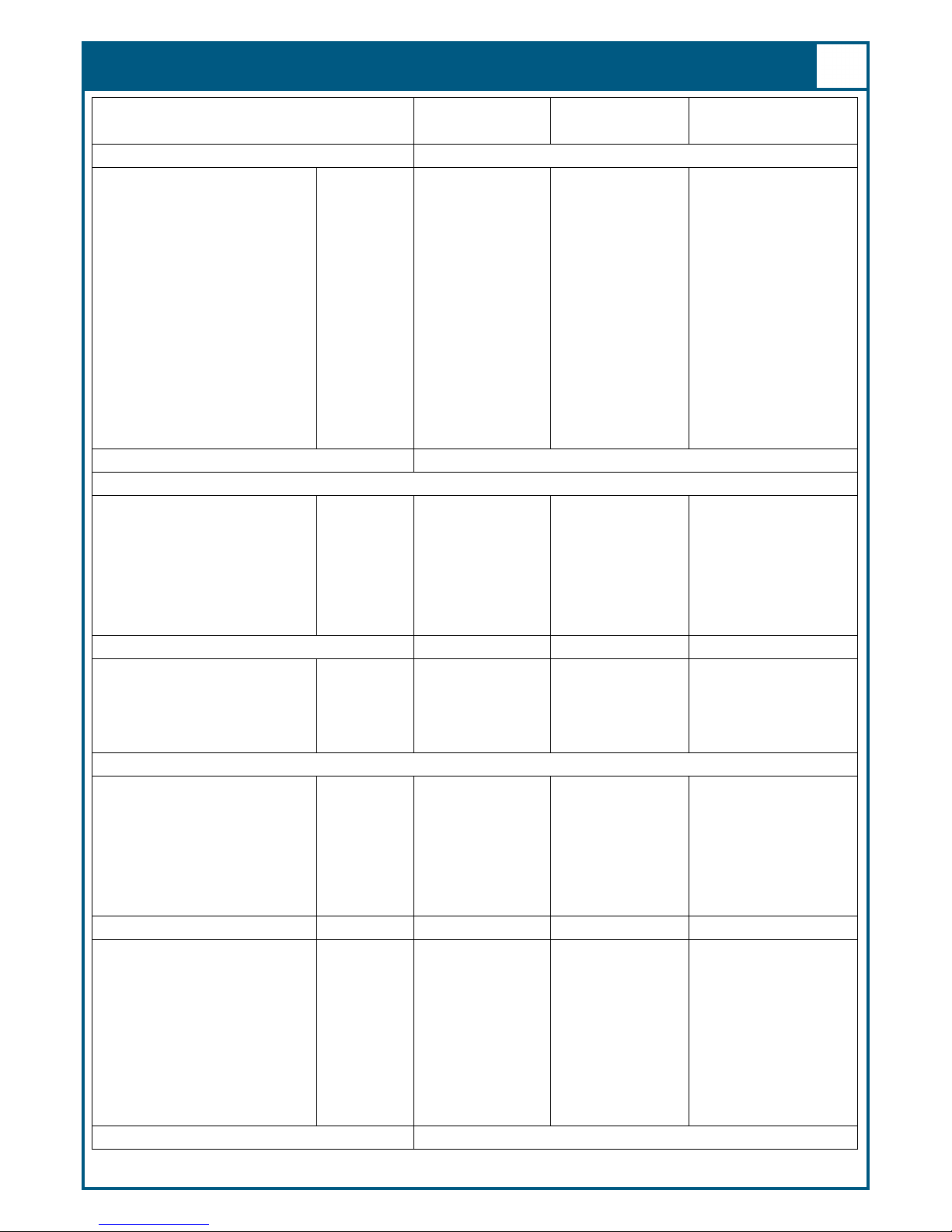
Specication
Model EF-450-DOT EF-450HP DOT EF-450VHP DOT
Part Number M4500C12-EZ H4500C12-EZ V4500C12-EZ
Dimensions
Footprint inch 31 x 31 31 x 31 31 x 31
(mm) 787 x 787 787 x 787 787 x 787
Cylinder Diameter inch 30 30 30
(mm) 762 762 762
Height inch 74 74 74
(mm) 1,880 1,880 1,880
Empty Weight Ibs 640 730 885
(Kg) 290 331 401
Capacity, Gross gallons 118 117 115
(liters) 448 443 437
MAWP psig 250 350 500
(kPa) 1,724 2,413 3,448
Design Specication DOT 4L
Safety Devices
Pressure Relief Valve psig 250 250 250
(kPa) 1,724 1,724 1,724
Inner Container Bursting Disc psig 356 525 750
(kPa) 2,455 3,620 5,171
Road Relief Valve psig 22 22 22
(kPa) 152 152 152
Pressure Control Devices
Economizer Setting psig 200 325 420
(kPa) 1,379 2,241 2,896
Pressure Building Setting psig 175 300 400
(kPa) 1,207 2,069 2,758
Gaseous Capacity NPT1
Nitrogen cu. ft. 9,250 8,750 7,687
(cu. M) 262 248 218
Oxygen cu. ft. 11,400 11,000 10,208
(cu. M) 323 312 289
Argon cu. ft. 11,000 10,700 9,947
(cu. M) 312 303 282
Weight of Contents1
Nitrogen lbs 670 634 557
(kg) 304 288 253
Oxygen lbs 946 907 845
(kg) 429 411 383
Argon lbs 1,134 1,102 1,028
(kg) 514 500 466
Gas Delivery Rate c 450 450 450
(cu. M/h) 12.7 12.7 12.7
NER (Percent of capacity per day O2) 1.0%
1 Based on liquid at full trycock for ASME designs and maximum liquid weight for DOT designs.
BT- 434 Rev.A
8
PIPING CIRCUITS
The following paragraphs describe the operation of the piping circuits of the system. The descriptions
refer to the main components of each circuit and are grouped by function. Reference the piping sche-
matic below and in the general arrangement drawing for the component designations. These compo-
nent and circuit descriptions should be understood before attempting operation.
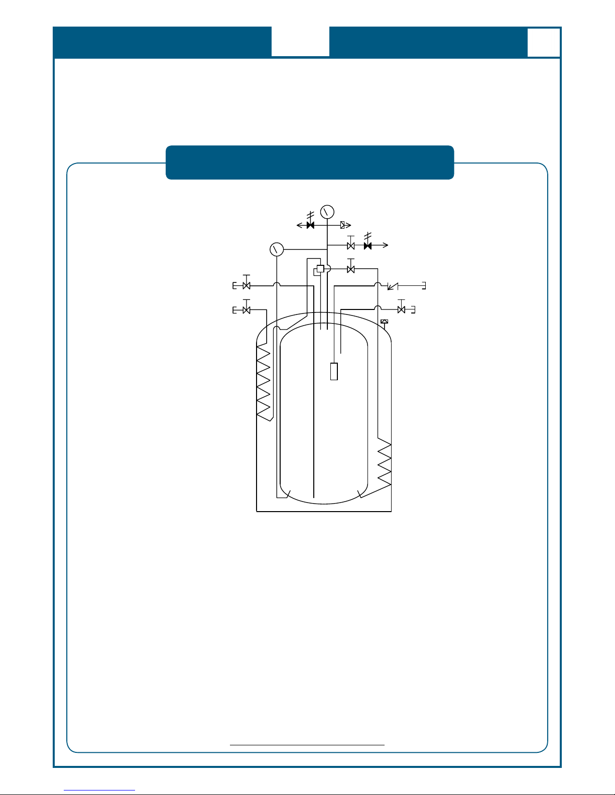
P&ID: MB-450 Standard Conguration
Figure 1-System Piping Schematic
VC-1
C
V-1
F
S
V-1
V-5
V
-
4
V-3
V
-
1
LI-1
PI-1
R
-
1
R-2
V-2
SV-1
SV-2
PBC-1
PCV-1
CN-2
CN-1
CN
-
3
CN
-
4
Legend
CN-1 Connection, Liquid Fill / Withdrawal LI-1 Liquid Level Gauge
CN-2 Connection, Full Trycock & Vent PI-1 Pressure Gauge
CN-3 Connection, Pump / Top Fill PBC-1 Pressure Building Coil
CN-4 Connection, Gas Withdrawal VC-1 Vaporizer Coil
V-1 Valve, Liquid Fill / Withdrawal PCV-1 Pressure Building Regulator
V-2 Valve, Full Trycock / Vent SV-1 SafetyValve
V-3 Valve, Gas Withdrawal SV-2 * SafetyValve, 22 psig
V-4 Valve, Pressure Building R-1 Safety Disc
V-5 * Valve, Isolation R-2 Outer Casing SafetyDisc
CV-1 Pump / Top Fill Check Valve FSV-1 Fill Stop Valve
Notes:
* Featured on DOT models only.

BT- 434 Rev.A
9
Fill and Vent Circuits
The liquid valve (V-1) communicates with the bottom of the vessel. A stainless steel tag labeled “LIQ-
UID” identies the valve and the liquid connection (CN-1). Liquid is added or removed from the vessel
through this connection and valve.
The vent / trycock valve (V-2) is attached to a vertical tube in the upper portion of the vessel. The open
end of the tube is positioned at 90% liquid level based on the vessel volume. Opening the vent valve
reduces pressure in the vessel during lling. It also severs as a “full trycock”, venting liquid from the
vessel when the liquid level exceeds 90%. A tag labeled “VENT” is attached to this valve.
Fill and Vent Circuits
Figure 2-Fill and vent circuits highlighted in blue.
V-1
V-2
CN-2
CN-1
BT- 434 Rev.A
10
Fill Circuit
The Fill circuit may be used for lling from the Microbulk Truck or for top lling by a cryogenic pump.
The check valve (CV-1) prevents product from escaping the vessel.
A ll stop valve (FSV-1) within the vessel prevents over lling. This device functions when lled by the
Microbulk Truck in automatic ll mode. The ll stop valve will not function when the vessel is lled by
a typical cryogenic pump.
Fill Circuit
Figure 3-Fill circuit highlighted in blue.
CV-1
CN-3

BT- 434 Rev.A
11
Pressure Building Circuit
The pressure building circuit serves to build pressure after lling the vessel. The circuit is also used to
ensure sucient driving pressure during high product withdrawal periods. Opening the pressure build-
ing circuit valve (V-4) permits the circuit to function. A stainless steel tag labeled “P.B.” is attached to
the valve. When the pressure inside the vessel drops below the pressure builder setting, the pressure
building stage of the pressure building/economizer regulator (PCV-1) opens. This creates a path from
the liquid in the bottom of the container to the gas space in the top. This path contains an internal
pressure building coil (PBC-1) to vaporize product as it ows from the bottom to the top of the vessel.
Liquid is expanded to a vapor and pressure is increased in the vessel. The pressure building coil is at-
tached to the inside surface of the vacuum jacket.
Pressure Building Circuit
Figure 4-Pressure building circuit highlighted in blue.
V-4
PCV-1

BT- 434 Rev.A
12
Gas Withdrawal Circuit
The gas withdrawal circuit vaporizes cryogenic liquid and warms it to ambient temperature for use
in the nal application. Opening the gas withdrawal valve (V-3) allows liquid, driven by the pressure
within the vessel, to ow through the vaporizer (VC-1). The vaporizer uses heat from the ambient air
to convert the liquid into a gas and warm it. The vaporizer, like the pressure building coil, is attached
to the inside surface of the vacuum jacket. The vaporizer is located in the upper ¾ of the jacket, the
pressure builder in the lower ¼.
Gas Withdrawal Circuit
Figure 5-Gas withdrawal circuit highlighted in blue.
V-3
CN-4
BT- 434 Rev.A
13
Economizer Circuit
The economizer circuit reduces product loss due to normal evaporation of the liquid within the vessel.
The economizer stage of the pressure building/economizer regulator (PCV-1) opens when the pressure
within the vessel exceeds the economizer setpoint. The economizer setpoint varies depending on the
model. This allows gas from the top of the vessel to ow into the vaporizer circuit. Provided that gas
from the vaporizer is being withdrawn for use, the vessel pressure will be reduced. The primary safety
valve (SV-1) will be prevented from opening, avoiding product loss.
Economizer Circuit
Figure 6-Economizer circuit highlighted in blue.
PCV-1

BT- 434 Rev.A
14
Safety Devices
The MB-450 features a safety valve to prevent over pressurization of the vessel. The safety valve (SV-
1) relieves pressure when it exceeds the maximum operating pressure of the vessel. The valve reseats
when pressure drops below this point. In addition, the primary safety valve is supported by a second-
ary relief device consisting of a rupture disc (R-1). The rupture disc requires replacement in the event a
safety valve malfunctions and allows vessel pressure to reach the burst pressure rating.
A relief valve (SV-2), set to open at 22 psig, is provided on the DOT models. Closing the isolation valve
(V-5) prevents ow through the relief valve. This feature is useful if it is necessary to transport the MB-
450 at a reduced pressure. It also allows liquid to be stored at a low pressure. This is reduces product
loses when using the MB-450 to dispense cryogenic liquid.
Safety Devices
Figure 7-Safety circuit highlighted in blue.
SV-1
PI-1
R-1

BT- 434 Rev.A
15
Instrumentation Circuits
The instrumentation consists of a pressure gauge and dierential pressure gauge. The pressure gauge
(PI-1) displays the inner vessel pressure in pounds-per-square-inch and kilopascals. The liquid level
gauge (LI-1) measures the dierence in pressure between the top and bottom of the vessel. Product
within the vessel creates a higher pressure at the bottom of the vessel than at the top. Readings on the
liquid level gauge are in inches of water. This reading, when compared to the contents chart attached
to the front of the vessel, allows accurate monitoring of the amount of product within the vessel.
Instrumentation Circuits
Figure 8-Instrumentation circuits highlighted in blue.
LI-1
PI-1

BT- 434 Rev.A
16
OPERATION
These instructions are for operators experienced with cryogenic equipment. Before operating the
system, become familiar with the safety precautions in this manual and in reference publications.
Study this manual and the general arrangement drawing located in the back of this manual thor-
oughly. Know the location and function of all system components.
Receiving Inspection
Handling
Customer Installed Equipment/Piping
Filling by Pressure Transfer
Freight and damage claims are the customer’s responsibility. Take time to visually inspect each ship-
ment in the presence of the carrier’s agent before accepting delivery. If any damage is observed, make
an appropriate notation on the freight bill. Ask the driver to sign the notation before receiving the
equipment. Do not accept equipment with damage that may aect serviceability.
The MB-450 should be handled only by a forklift or crane. Ensure that handling equipment has ade-
quate rated capacity for the system weight listed on the general arrangement drawing in the appendix.
The MB-450 is a rugged product intended for years of industrial use. However, take care when mov-
ing the unit. Abuse (dropping or careless handling by forklift) may aect the integrity of the insula-
tion system or damage piping. Always transport, operate, and store the unit in the vertical position.
Never place the unit on its side.
Important: When lifting by crane, use the lift-eyes provided on the top of the jacket. Never lift the unit over-
head.
When installing the MB-450 for remote lling, be sure to follow accepted design practices for cryogenic
equipment. All equipment must be cleaned for oxygen service. Be sure to include pressure relief valves in
all piping where liquid product could be trapped between closed valves, regulators, etc.
Designing safe and eective cryogenic systems requires extensive knowledge and experience. Persons
lacking the necessary skills are urged to seek competent advice before attempting to design cryogenic
systems.
Design and consultation services are available from the factory at the location shown at the front of the
manual.
Filling by pressure transfer is accomplished by lowering the pressure in the MB-450 below that of the
source vessel. Typically the source vessel is a cryogenic bulk tank or truck mounted vessel. The pres-
sure is reduced in the MB-450 by venting gas through the vent valve (V-2). Liquid is pushed by pressure
from the bulk tank and into the MB-450.
CAUTION: Follow the safety precautions at the beginning of this manual. Accidental contact with liquid
or
cold gas can occur during lling.
A cryogenic transfer hose equipped with a relief valve and dump valve should be used to connect the
MB-450 to the liquid source. Follow the instructions below to ll by pressure transfer:

BT- 434 Rev.A
17
OPERATION
Withdrawing Gas
Filling by Pump Transfer
Filling for Road Transport
1. Visually inspect the MB-450, transfer hose, and bulk tank piping. Do not attempt to fill the unit if
any components are broken or missing.
2. Connect a transfer hose from the bulk tank to the liquid connection (CN-1).
3. Open the liquid valve (V-1) and vent valve (V-2) to begin the fill.
4. When liquid issues from the vent valve, the vessel is full. A 10% gas head space will remain above
the liquid. Close the liquid valve (V-1).
5. Once liquid stops issuing from the vent valve (V-2), close the vent valve.
6. Close the liquid source supply valve and open the transfer hose dump valve.
7. Disconnect the transfer hose from the liquid connection (CN-1).
When a pump is used to ll the container, the pump / top ll connection (CN-3) should be used. Closely
monitor the vessel pressure during the ll. If the vessel pressure approaches the relief valve setting
or the pump pressure rating, shut down the pump. Open the vent valve (V-2) to reduce pressure as
needed.
When lling using the Taylor-Wharton Express truck in automatic mode, the ll is stopped at a level
providing an adequate gas head space.
When using a traditional pumping system, the vent valve (V-2) should remain open during the ll. Moni-
tor the product exiting the vent valve closely. When liquid issues from the vent valve (V-2) immediately
stop the pump. Once liquid stops issuing from the vent valve, close the vent valve.
The DOT-4L design vessels may be transported over the road while containing product. When filling
these vessels for transport, it is recommended that they be placed on a scale during the fill. The
weight of the contents should not exceed the maximum weight allowed by the DOT (Department of
Transportation).The weight of contents can be found on the Specifications page.
The vessel tare weight, labeled TW, can be found on the nameplate located on the upper head of the
vessel jacket. Add the weight of contents for the appropriate vessel design and gas service to the
tare weight of the vessel. The weight of the full vessel must not exceed the sum of the tare weight
and weight of contents.
To withdraw gas from the MB-450 connect a suitable line regulator to the gas withdrawal connection
(CN-4). Connect the outlet of the regulator to the application. Follow these steps:
1. Close the isolation valve (V-5) for the 22 psig relief valve (SV-2) if so equipped.
2. Open the pressure building valve (V-4). Monitor the pressure gauge (PI-1). When the pressure
exceeds the desired delivery pressure, continue.
3. Open the gas withdrawal valve (V-3).
4. Adjust the line regulator to desired delivery pressure.

BT- 434 Rev.A
18
OPERATION
Withdrawing Liquid
Changing Gas Service
Attach a transfer hose from the receiver vessel to the MB-450 liquid connection (CN-1) and open the
adjacent liquid valve (V-1). The pressure in the container will drive liquid product out through the valve
as long as the container pressure exceeds that of the receiver.
The MB - 450 may be used for argon, oxygen, or nitrogen service. Follow these steps to properly
change gas service:
1. Safely empty all liquid from the container.
2. Open the pressure building valve (V-4) and the vent valve (V-2) to vaporize any residual liquid
that may remain in the bottom of the vessel. It may require an hour or longer to vaporize all the
residual liquid.
3. To ensure purity, it is recommended that the MB-450 be evacuated with a suitable vacuum pump.
The ultimate vacuum reading should be at least 20 inches of mercury.
4. Replace the fittings for the vent, liquid, and use connections with the appropriate fittings shown
in the chart below. Use Teflon tape or another suitable thread sealant when threading the fittings
into the connections.
5. Remove any decals identifying the previous gas service. Attach new gas service identification
decals.
Gas Service Valve Description TW Part Number
Oxygen
Use Fitting CGA 540 x 3/8” NPT 7114-0163
Liquid & Vent Fitting CGA 440 x 3/8” NPT 6514-8992 (2 required)
Top Fill CGA 440 x 1/2” NPT 6514-8990
NA Oxygen Service Decal GL55-9C52
Nitrogen
Use Fitting CGA 580 x 3/8” NPT 7114-0164
Liquid & Vent Fitting CGA 295 x 3/8” NPT 7355-4712 (2 required)
Top Fill CGA 295 x 1/2” NPT 7355-4698
NA Nitrogen Service Decal GL55-9C51
Argon
Use Fitting CGA 580 x 3/8” NPT 7114-0164
Liquid & Vent Fitting CGA 295 x 3/8” NPT 7355-4712 (2 required)
Top Fill CGA 295 x 1/2” NPT 7355-4698
NA Argon Service Decal GL55-9C53
BT- 434 Rev.A
19
MAINTENANCE
Routine inspections of the system are recommended. The need for maintenance usually becomes appar-
ent from inspection and indications of improper operation. Typical trouble indications include leakage
from valves or piping connections and excessive venting through relief valves. Keep a permanent log of
all inspections and repairs performed. Such a log can be valuable in evaluating performance and schedul-
ing maintenance.
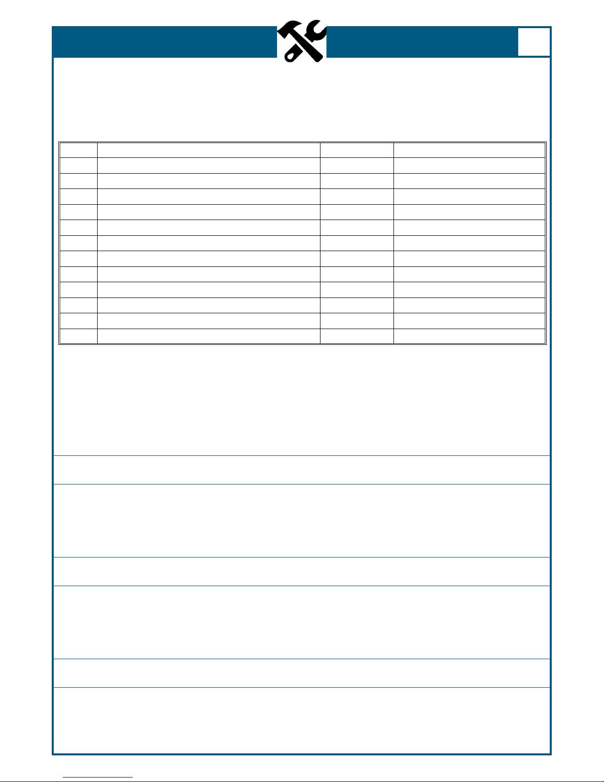
Date Nature of Work (Describe in Full) Remarks Service men’s Signature
Always observe the safety precautions at the front of this manual and follow the instructions given in this
section. Before working on the system, properly empty the vessel of liquid and relieve pressure on the
vessel and piping. Do not allow unqualied persons to attempt repairs on this equipment. Refer to the
Trouble - Remedy Guide in this manual for assistance in troubleshooting.
Figure 9: Inspection and Repair Log (Sample Form)
Leak Test
Globe Valves
Regulator
After making repairs requiring disassembly or replacement of components, leak test all valves or piping
joints that were taken apart and reconnected. Apply leak detector uid to the test surface. Large leaks
instantly form large bubble clusters, while ne leaks produce white foam that builds up more slowly. All
leaks must be repaired and retested before the system is returned to service.
All of the globe valves (V-1, V-2, V-3, & V-4) are an integral part of the system and are not easily removable.
However, the valves may be rebuilt without removal from the system. All of the globe valves use the same
rebuild kit. The Taylor-Wharton part number for the rebuild kit is 1750-9C35. All valve components, except
the body, are provided in the kit.
A dual stage, spring-loaded regulator (PCV-1) is employed for the pressure building/economizer circuit.
The regulator may be adjusted without removal from the system. The following procedure describes the
process:

BT- 434 Rev.A
20
MAINTENANCE
1. Fill the container with liquid product.
2. Open the pressure building valve and allow the container pressure to stabilize for about an hour. Note
the pressure.
3. Loosen the adjustment screw on the top of the regulator to raise or lower the pressure to the desired
point. When decreasing the setting, the pressure building valve must be closed and the container
vented to a lower pressure. Repeat step two and observe the change.
For more accurate adjustment it is recommended that the regulator be removed from the system. A reg-
ulator bench adjustment xture should be used. The gure below shows a typical setup.
Port Stamped
“P.B. IN”
Regulator to be
Adjusted Top View
On/O
Valve
Dum
p
Valve
Regulator to
be Adjusted
Pressure
Gauge
Regulator
High Pressure
Cylinder
Figure 10: Regulator bench adjustment xture.
1. Leak test joints between the high pressure cylinder regulator and the dump valve. Joints must be leak
free before proceeding.
2. Close the on/o valve and the dump valve.
3. Open the high pressure cylinder valve.
4. Set the high pressure regulator above the desired set point for the pressure builder.
5. Slowly open the on/o valve and observe the downstream pressure gauge.
6. When the regulator under adjustment closes, the pressure-building. Set point is indicated on the
downstream pressure gauge.
7. Close the on/o valve and open the dump valve.
8. To reset the regulator, loosen the lock nut on the adjusting screw. Raise the set point by turning the
adjusting screw clockwise; lower the set point by turning the screw counterclockwise. After adjust-
ment, repeat steps 5 and 6 to check the setting before reinstalling the regulator on the liquid contain-
er.
Table of contents
Popular Storage manuals by other brands


 user guide")


Hitachi
Hitachi T7K250 - Deskstar - Hard Drive Quick installation guide

Philips
Philips FM01SW81 Specifications

Western Digital
Western Digital WDBAAG0010HCH - My Book For Mac quick start guide

I/O Magic
I/O Magic I160HD25G2 Specifications

Toshiba
Toshiba MK3006GAL user manual

ATON
ATON RA.Store-K-F installation manual


