tbs electronics Omnicharge OCD12/12-50 User manual

Programmable DC to DC battery chargers
Omnicharge DC
OCD12/12-50 (12V/50A)
OCD12/24-30 (24V/30A)
Owner’s manual
Gebruiksaanwijzing
Bedienerhandbuch
Mode d’emploi
Manual del propietario
TBS ELECTRONICS BV
De Marowijne 3, 1689AR, Zwaag, The Netherlands
tbs-electronics.com

1

2
Notice of Copyright
Omnicharge DC 30-50A DC to DC battery charger owner’s manual © 2020 TBS Electronics
BV. All rights reserved. No part of this document may be reproduced in any form or disclosed
to third parties without the express written permission of TBS Electronics BV, De Marowijne
3, 1689AR, Zwaag, The Netherlands. TBS Electronics BV reserves the right to revise this
document and to periodically make changes to the content hereof without obligation or
organization of such revisions or changes, unless required to do so by prior arrangement.
Exclusions for documentation and product usage
UNLESS SPECIFICALLY AGREED TO IN WRITING, TBS ELECTRONICS BV (“TBS”) :
1. MAKES NO WARRANTY AS TO THE ACCURACY, SUFFICIENCY OR SUITABILITY OF ANY
TECHNICAL OR OTHER INFORMATION PROVIDED IN ITS MANUALS OR OTHER
DOCUMENTATION
2. ASSUMES NO RESPONSIBILITY OR LIABILITY FOR LOSSES, DAMAGES, COSTS OR EXPENSES,
WHETHER SPECIAL, DIRECT, INDIRECT, CONSEQUENTIAL OR INCIDENTAL, WHICH MIGHT
ARISE OUT OF THE USE OF SUCH INFORMATION. THE USE OF ANY SUCH INFORMATION
WILL BE ENTIRELY AT THE USER’S RISK
3. REMINDS YOU THAT IF THIS MANUAL IS IN ANY LANGUAGE OTHER THAN ENGLISH OR
DUTCH, ALTHOUGH STEPS HAVE BEEN TAKEN TO MAINTAIN THE ACCURACY OF THE
TRANSLATION, THE ACCURACY CANNOT BE GUARANTEED.
4. MAKES NO WARRANTY, EITHER EXPRESSED OR IMPLIED, INCLUDING BUT NOT LIMITED
TO ANY IMPLIED WARRANTIES OF MERCHANTABILITY OR FITNESS FOR A PARTICULAR
PURPOSE, REGARDING THESE TBS PRODUCTS AND MAKES SUCH TBS PRODUCTS
AVAILABLE SOLELY ON AN “AS IS” BASIS.
5. SHALL IN NO EVENT BE LIABLE TO ANYONE FOR SPECIAL, COLLATERAL, INCIDENTAL, OR
CONSEQUENTIAL DAMAGES IN CONNECTION WITH OR ARISING OUT OF PURCHASE OR
USE OF THESE TBS PRODUCTS. THE SOLE AND EXCLUSIVE LIABILITY TO TBS, REGARDLESS
OF THE FORM OF ACTION, SHALL NOT EXCEED THE PURCHASE PRICE OF THE TBS
PRODUCTS DESCRIBED HERE IN.
Document name, date and part number
“OCD 30-50 Manual Rev2endfs”, May 2020, webversion

3
English
Page 4
Nederlands
Pagina 21
Deutsch
Seite 37
Francais
Page 56
Español
Página 72

4
TABLE OF CONTENTS
1. INTRODUCTION ...................................................................................................................... 5
1.1 Intended product use .................................................................................................. 5
1.2 Important safety information...................................................................................... 5
2. INSTALLATION ........................................................................................................................ 7
2.1 Unpacking....................................................................................................................7
2.2 Mounting ..................................................................................................................... 7
2.3 Wiring details............................................................................................................... 8
3. GENERAL FUNCTIONALITY.................................................................................................... 13
3.1 The charging process.................................................................................................13
3.2 Charger operation using the main On/Off control input ..........................................14
3.3 Charger operation without using the main On/Off control input............................. 14
3.4 LED indicators ............................................................................................................ 15
4. TROUBLESHOOTING GUIDELINE .......................................................................................... 16
5. TECHNICAL SPECIFICATIONS ................................................................................................ 18
6. WARRANTY CONDITIONS .....................................................................................................19
7. DECLARATION OF CONFORMITY ..........................................................................................20

5
1. INTRODUCTION
Thank you for purchasing a TBS Electronics (TBS) Omnicharge DC to DC battery charger.
Please read this owner’s manual for information about using the product correctly and
safely. Keep this owner’s manual and all other included documentation close to the product
for future reference. For the most recent manual revision, please check the downloads
section on our website.
The purpose of this owner’s manual is to provide explanations and procedures for installing,
configuring and operating the battery charger. The installation instructions are intended for
installers that should have knowledge and experience in installing electrical equipment,
knowledge of the applicable installation codes, and awareness of the hazards involved in
performing electrical work and how to reduce those hazards.
1.1 Intended product use
The Omnicharge DC battery chargers are primarily intended to charge an auxiliary or service
battery from a vehicle starter battery. The input battery voltage can be above, below or
equal to the output battery voltage. An Omnicharge DC charger allows the auxiliary battery
to be perfectly charged regardless of the input voltage, while being protected against
damage due to peak voltages.
The Omnicharge DC battery chargers are compatible with vehicles that are equipped with
variable output smart alternators (EUR 6+). The Omnicharge DC can start charging based on
a programmable input voltage range only, or in combination with an engine run signal. There
is also a separate (BMS-) control input available that enables external control for charger-on
and -standby.
1.2 Important safety information
This section contains important safety information for the Omnicharge DC battery charger.
Each time, before using the Omnicharge DC battery charger, READ ALL instructions and
cautionary markings on or provided with the battery charger, and all appropriate sections of
this guide. This battery charger contains no user serviceable parts. Opening up the battery
charger will void product warranty.
WARNING
FIRE AND/OR CHEMICAL BURN HAZARD
Do not cover or obstruct any air vent openings and/or install in a zero clearance
compartment.

6
WARNING
SHOCK HAZARD. KEEP AWAY FROM CHILDREN!
Avoid moisture ingress. Never expose the unit to snow, water, etc.
WARNING
FAILURE TO FOLLOW THESE INSTRUCTIONS CAN RESULT IN DEATH OR SERIOUS INJURY:
1. When working with electrical equipment or lead acid batteries, have someone nearby in
case of an emergency.
2. Study and follow all the battery manufacturer’s specifc precautions when installing, using
and servicing the battery connected to the charger.
3. Wear eye protection and gloves.
4. Avoid touching your eyes while using this unit.
5. Keep fresh water and soap on hand in the event battery acid comes in contact with eyes.
If this occurs, clean right away with soap and water for a minimum of 15 minutes and
seek medical attention.
6. Batteries produce explosive gases. DO NOT smoke or have an open spark or fire near the
system.
7. Never attempt to re-charge a damaged, frozen or non-rechargeable battery.
8. Keep unit away from moist or damp areas.
9. Avoid dropping any metal tool or object on the battery. Doing so could create a spark or
short circuit which goes through the battery or another electrical tool that may create an
explosion.
10.There are no user serviceable parts inside in the charger’s enclosure.
WARNING
EXPLOSION HAZARD!
Do not use the battery charger in the vicinity of flammable fumes or gases.
!
CAUTION
LIMITATIONS OF USE
Do not use in connection with life support systems or other medical equipment or devices.
This battery charger is not to be used by persons with reduced physical or mental
capabilities or lack of knowledge and experience. Not to be operated or used by children.
7
2. INSTALLATION
2.1 Unpacking
The charger package should contain the following items :
-Battery charger
-3x rubber cable grommets
-Battery temperature sensor (3m)
-Owner’s manual
-3x M6 crimp terminals
!
CAUTION
After unpacking, check if the product shows any mechanical damage. Never use the product
when the enclosure shows any visual damage caused by harsh handling, or when it has
been dropped accidentally. Contact your local supplier for further information.
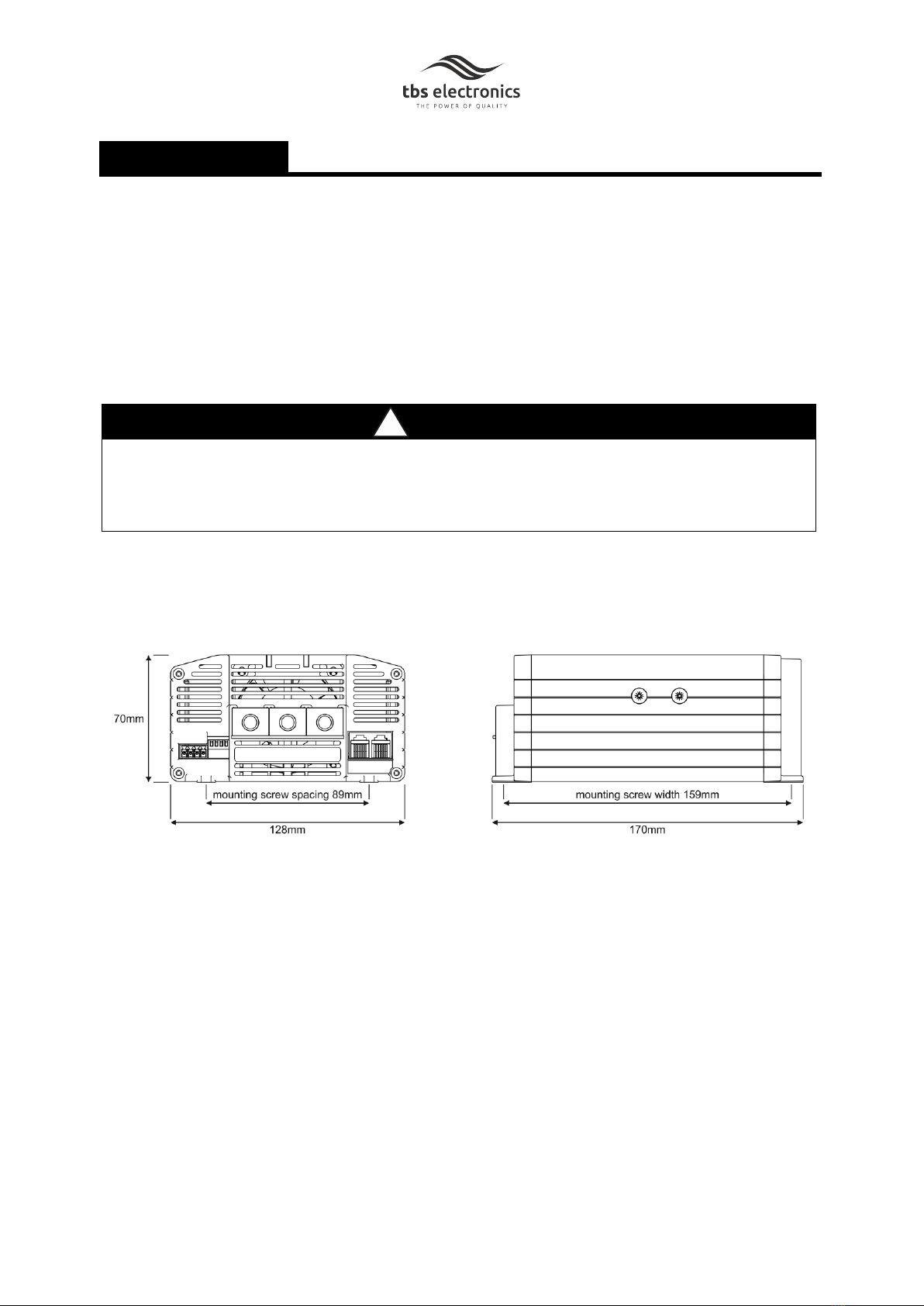
2.2 Mounting
Please see the image below for the product dimensions and mounting screw distances.
Further location and mounting details:
1. Choose an appropriate mounting location in a well ventilated room that is protected
against rain, snow, spray, vapour, moisture and dust.
2. Make sure that the ambient temperature is between -20°C and +60°C. Above +40°C the
charge will automatically derate the output power.
3. Do not expose the charger to any heat source (such as direct sunlight or heating). Avoid
additional heating of the product. Also avoid charger exposure to excessive vibration.
4. Never install the charger in an enviroment where there is danger of gas or dust
explosions, like in the same compartment as the batteries or directly above vented
batteries.
5. When installing the charger horizontally (floor-mounting), any mounting direction is

8
acceptable. When installing vertically, please observe the following preferred enclosure
orientations:
6. Use the base of the charger as a mounting template to mark the positions of the fixing
screws.
!
CAUTION
Keep a clear space of at least 10 cm around this product for cooling purposes!
2.3 Wiring details
WARNING
For user safety during installation, please make sure that the output of the supplying source
is switched off (temporary remove fuses from the fuseholders) and that no consumers are
connected to the batteries.
!
CAUTION
Please double check if the battery voltages match the specifications of the used charger
model.
!
CAUTION
Always connect ground (- GND) first followed by the service (+ OUT) battery and lastly the
starter (+ IN) battery.
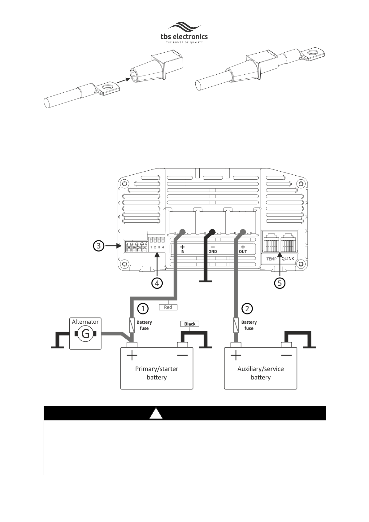
Before connecting the main DC cables, make sure to slide the included rubber grommets
over these cables like shown in the next image.
9
When the DC cables are connected to the charger, the rubber grommets can be slid towards
the charger’s front panel until the screw connections are completely covered.
Please see the image below for further wiring details.
!
CAUTION
Double check for correct polarity, before connecting the battery cables to the battery!
Wrong polarity will blow an internal fuse and the charger must be returned for service.
Always keep positive and negative cables close to each other to minimize electromagnetic
fields.

10
Please consult the following table to determine the correct input battery cable- and
fuse size for each model. Using a smaller cable size will cause additional losses and may
result in improperly charged batteries. Fire and burning hazards are present if the
battery cables are insufficiently sized for the expected current. Always keep the cable
length as short as possible!
Model
Minimum Cable size
Recommended
Cable size
Battery fuse
(quick type)
OCD 12/12-50
16mm2(AWG6)
25mm2(AWG4)
70-90Amp
OCD 12/24-30
16mm2(AWG6)
25mm2(AWG4)
70-90Amp
Please consult the following table to determine the correct output battery cable- and
fuse size for each model. Using a smaller cable size will cause additional losses and may
result in improperly charged batteries. Fire and burning hazards are present if the
battery cables are insufficiently sized for the expected current. Always keep the cable
length as short as possible!
Model
Minimum Cable size
Recommended
Cable size
Battery fuse
(quick type)
OCD 12/12-50
16mm2(AWG6)
25mm2(AWG4)
60-80Amp
OCD 12/24-30
10mm2(AWG8)
16mm2(AWG6)
40-50Amp
Please see the image below for the control wire connection locations.
Connection 1 is the main On/Off control input and can only be used when DIP switch 4
is set to off. This input can be used to enable or disable the charger and is ‘active high’.
When a voltage higher than 2V is applied to this input, the charger turns on. When a
voltage lower than 1V is applied, the charger turns off and draws zero current. The
maximum input voltage is 32V. In a vehicle application is it recommended to connect
11
this input to the engine run signal. Contact your vehicle distributor to find out the most
suitable connection.
BMS input connection 2 can be used to force the charger in standby mode. In this
mode the charger stops charging, but the internal circuits stay active to immediately
resume charging once allowed again. This input can be used to connect to a Lithium
battery BMS in order to stop the charging process if required. By default this input is
‘active low’(< 1V is On and > 3V is Stand by), but this can be changed to ‘active high’as
well by the TBS Dashboard or Dashboard Mobile app. The maximum input voltage is
32V.
Connection 3 is an open collector output that can be used to for example connect to a
remote indicator light. The maximum switching voltage and current are respectively
32V and 150mA. By default this output is active (low) when the charger is charging OR
when charging is finished. Other active conditions can be selected in the TBS
Dashboard or Dashboard Mobile apps.
Connection 4 is reserved for future use and has no active functionality yet.
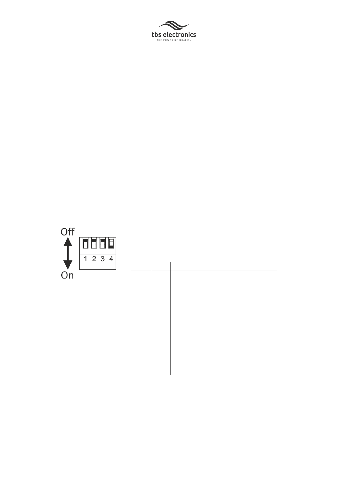
DIP switch settings
DIP switch 1 and 2 are used select the desired charge
program for the connected output battery. Please see the
table below:
DIP1
DIP2
Battery type / Charge program 1) 2)
Off
Off
Flooded (default setting)
Bulk/Abs voltage = 14.4V (28.8V)
Float voltage = 13.5V (27.0V)
Off
On
GEL
Bulk/Abs voltage = 14.2V (28.4V)
Float voltage = 13.5V (27.0V)
On
Off
AGM
Bulk/Abs voltage = 14.7V (29.4V)
Float voltage = 13.6V (27.2V)
On
On
LiFePo4
Bulk/Abs voltage = 14.4V (28.8V)
Float voltage = 13.8V (27.6V)
1) Charge voltage value between brackets are for OCD
12/24-30 model
2) All standard charge voltage values are configurable using
the TBS Dashboard and Dashboard Mobile apps.
DIP switch 3 is reserved for future use (default off)
DIP switch 4 can be used to bypass the On/Off control input
12
(see point 3 above). When this DIP switch is set to On
(default setting), the On/Off control input is bypassed and
the charger will always operate, independent of the status at
the control input. When this DIP switch is set to Off, the
charger is controlled by the On/Off control input. This
setting is recommended for vehicle applications with a
proper engine run signal.
!
CAUTION
Invalid battery type settings can cause serious damage to your batteries and/or
connected battery loads. Always consult your battery’s documentation for the
correct charge voltage settings.
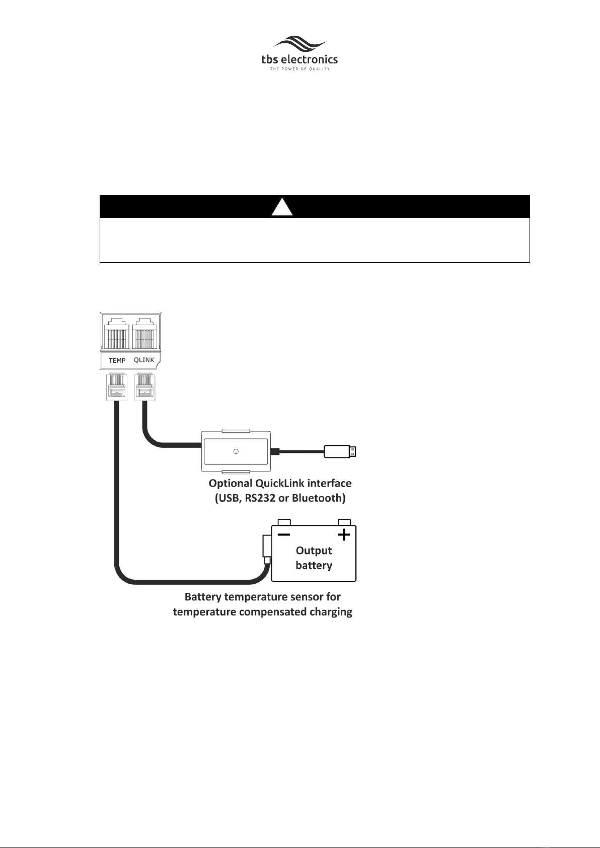
The remaining connection options are shown below
The optional QuickLink communication Kits allow the charger to be programmed and
monitored using the TBS Dashboard software on PC (via USB or RS232) or the
Dashboard Mobile app on iOS and Android platforms (via Bluetooth).
Always connect the battery temperature sensor to the battery that is being charged
(output battery). The charger automatically compensates the charge voltages against
battery temperature. This means that the charge voltages are slightly increased at
lower temperatures and decreased at higher temperatures (-30mV/°C at 12V chargers
and -60mV/°C at 24V chargers). This way, overcharging is prevented which prolongs
your battery's lifetime. When the LiFePo4 charge program is selected, the charge
13
voltages are not compensated against temperature. However, the temperature sensor
is still used to prevent charging the lithium battery when the temperature has dropped
below 0°C.
3. GENERAL FUNCTIONALITY
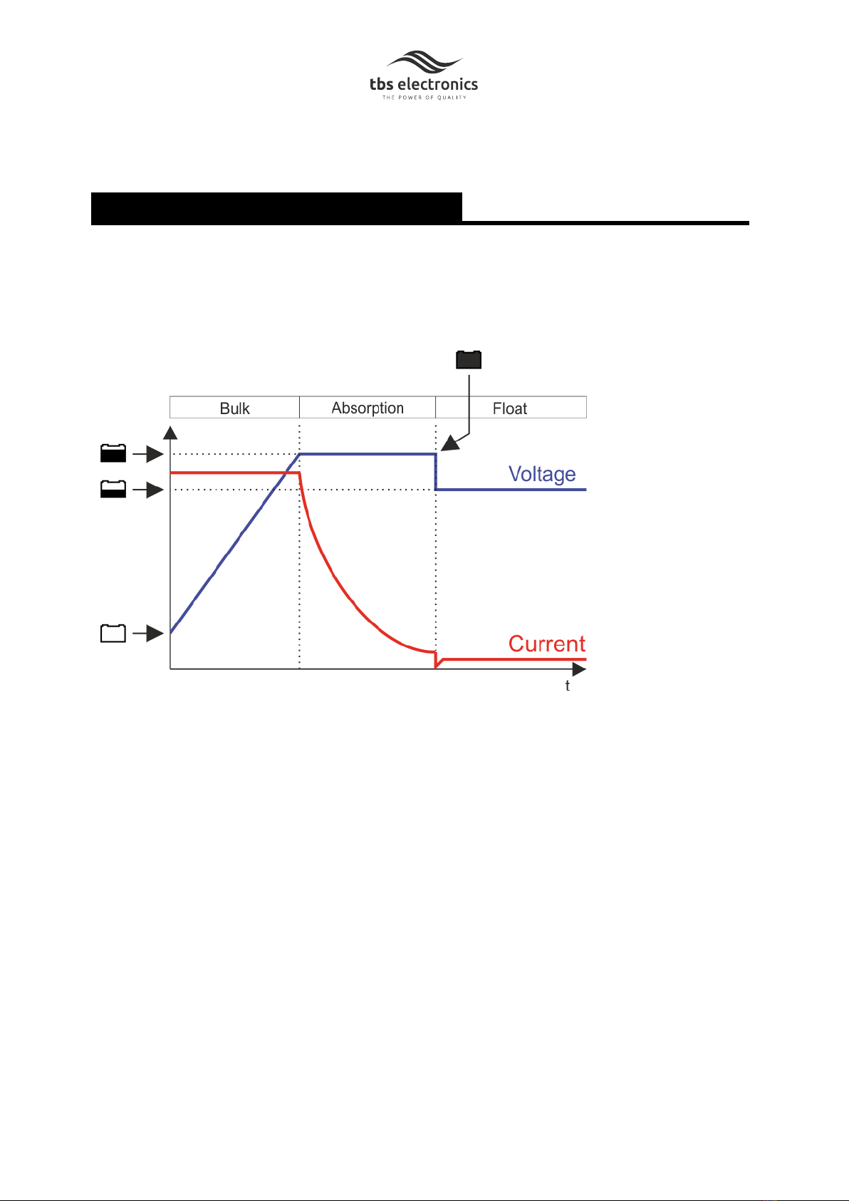
3.1 The charging process
All selectable charge programs, perform a three stage IUoUo charging process comprising of
a “Bulk” , an “Absorption”, and a “Float” stage. The image below visualizes the three stage
charging process:
When charger is turned on, it will start in the Bulk stage. In this stage the charger delivers full
output current and typically returns approximately 80% of charge back into the battery once
the absorption voltage is reached. When this voltage has been reached, the Absorption
stage will be entered. This stage will return the final 20% of charge to the battery. The
output voltage is kept at a constant level and the charge current decreases as a function of
the battery's state of charge. When the charge current has dropped below a certain value,
the Float stage will be entered. For lithium batteries, more than 80% of charge has been
returned to the battery already. So for this chemistry the Absorption stage will be relatively
short.
In the Float stage the battery voltage will be held constant at a safe level for the battery. It
will maintain the battery in optimal condition for as long as the battery remains connected
to the activated charger. Connected battery loads will be directly powered by the charger
up to the charger's maximum output current level.

14
3.2 Charger operation using the main On/Off control input
In order to activate the charger, a positive (high) signal must be applied to the main On/Off
control input while DIP switch 4 must be in the Off position. In a vehicle application, this is
typically the engine run signal. After a short delay of a few seconds, the charger will normally
start the charging process. There is however a second condition that must be met before the
charger starts the charging process and this is the input voltage level. The input battery
voltage must be above a certain level in order to allow the output battery to be charged.
Additionally, this condition must also be met for a preset amount of time. Please see the
table below showing all factory default voltage and time delay values that are stored inside
the Omnicharge DC charger:
Parameter1)
Default value
OCD 12/12-50
Default value
OCD 12/24-30
Turn on input voltage
> 12.5V
> 12.5V
Delay
10 sec
10 sec
Turn off input voltage (slow)
< 12.4V
< 12.4V
Delay
3 min
3 min
Turn off input voltage (fast)
< 12.0V
< 12.0V
Delay
1 sec
1 sec
1) All parameters are configurable using the TBS Dashboard and Dashboard Mobile apps
As can be seen in the above table, there are two low input voltage turn off levels. The ‘slow’
off level is allowed to be exceeded for a longer time than the ‘fast’off level. This results in a
stable charge process while still avoiding a too deeply discharged input battery.
!
CAUTION
If the main On/Off control input is connected to the ignition- instead of an engine running
signal, while the turn off input voltage levels are set to relatively low values, please make
sure to start the engine in a timely manner to avoid discharging the starter battery too
much.
3.3 Charger operation without using the main On/Off control input
When there is no engine run signal available or when the charger must always remain
activated, DIP switch 4 must be set to ON. In this mode however, the input voltage
requirements as shown in the table of chapter 3.2 still applies. So the charger will only start
charging when these requirements are met.
15
!
CAUTION
Please be aware that in this always on mode, the charger will continue to draw a small
current (< 35mA) from the input battery, even when the turn on input voltage condition has
not been met. This could result in a discharged input battery if allowed for an extended
amount of time.
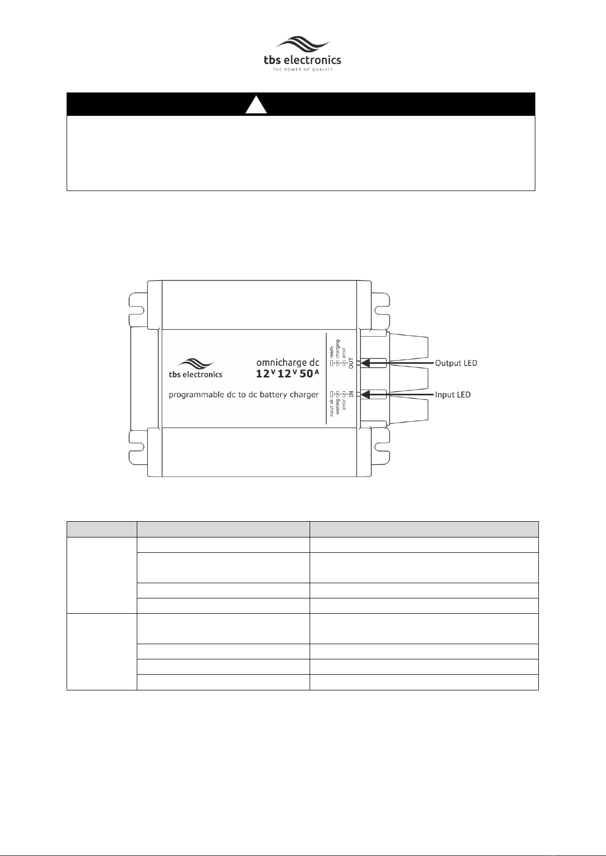
3.4 LED indicators
The Omnicharge DC units are equipped with individual LEDs for the input- and the output
side. Please see the image below for the location of these LEDs:
The table below explains all available LED conditions:
LED
Status
Explanation
Input LED
Off
Charger off
Flashing orange
Input voltage too low or turn on delay not
expired yet
Continuous green
All input conditions are OK for charging
Flashing red
Error (see LED error table below)
Output LED
Off
Charger off, or charging still blocked by
input conditions not being met
Flashing green
Charging in progress
Continuous green
Charging finished (Float stage)
Flashing red
Error (see LED error table below)

16
The LED error table below explains what error types are linked to what LED blinking
sequences:
Input LED
Output LED
Error type
Flashing red (1 blink)
Input overvoltage
Flashing red (1 blink)
Output overvoltage, Output undervoltage,
battery temperature too low or too high
Flashing red (2 blinks)
Output overload / short circuit
Flashing red (3 blinks)
Charger high temperature
4. TROUBLESHOOTING GUIDELINE
Please see the table below if you experience any problems with the Omnicharge DC battery
charger and/or the installation.
Problem
Possible cause
Remedy
Omnicharge DC is not
working at all.
No input voltage
Check wiring and input fuse
Input voltage is too low
Check input voltage, adjust
the input voltage settings,
start engine
No positive signal on main
On/Off control wire
Check wiring, fuses and
status of engine run signal
Positive signal on BMS input
Check output battery BMS
status
Very poor input battery
condition
Replace battery
The battery is not being
charged up to it’s maximum
capacity.
Incorrect absorption charge
voltage setting
Check the battery type
selection for correct setting.
Or adjust the absorption
voltage
Incorrect charge current
setting
Make sure that the
maximum output current
setting is at maximum level
(check if allowed by battery
manufacturer)
Too much voltage loss in
battery cables and/or
connections
Make sure that the battery
cables have a large enough
diameter. Check if all DC
connections are solidly
made.

17
Additional battery loads are
consuming too much current
during charging
Turn-off or disconnect all
battery loads
Charge current is too low.
High ambient temperature
Try to lower the ambient
temperature around the
charger
Charger is operating in the
absorption charging stage.
Do nothing. The battery is
almost fully charged and
consumes less current by
itself.
Charge voltage is too low.
The charge voltage is being
compensated by the battery
temperature sensor to
protect the battery.
Do nothing or try to cool
down the ambient
temperature around the
battery.
Wrong battery type selected,
or charge voltage needs to
be adjusted
Select the correct battery
type or adjust the charge
voltage in the setup menu
DC cables too thin
Install larger DC cables. See
the DC cable size table in
chapter 2.3.
Battery load current is higher
than the charger’s output
current.
Reduce or remove the
battery load.
LEDs blink red
Error detected
Check LED error table in
chapter 3.4
If none of the above remedies will help solving the problem you encounter, it’s best to
contact your local TBS distributor for further help and/or possible repair of your Omnicharge
DC unit. Do not disassemble the charger yourselves as this will void your warranty.

18
5. TECHNICAL SPECIFICATIONS
Parameter
OCD 12/12-50
OCD12/24-30
Nominal input voltage
12Vdc
Input voltage range
10.0 –16.0Vdc
Maximum input current
65Adc
Current consumption (inactive)
< 0.25mA
Current consumption
(noload/standby)
< 35mA
< 45mA
Nominal output voltage
12Vdc
24Vdc
Output voltage range
12.0 –16.0Vdc
24.0 –32.0Vdc
Maximum output current 1)
50A
30A
Charge characteristic
IUoUo, intelligent 3-stage, temp. Compensated
Supported battery types 2)
Flooded / Gel / AGM / LiFePO4
Operating temperature range
-20°C ... +60°C
Storage temperature range
-30°C …+70°C
Cooling
Variable speed fan
Communication port
QuickLink
Temperature sensor port
Yes (sensor included)
Engine run / activate input port
Yes (> 2.0Vdc = Active and < 1.0Vdc = Inactive)
BMS input port
Yes (> 3.0Vdc = Standby and < 1.0Vdc = Active)
Status output port
Yes (open drain, 32Vdc / 150mA max, five assignable
status types)
Protections
High/low input voltage, high temperature, output short
circuit and reverse battery polarity (input + output)
Indications
Input status, output (charge-) status, error
Battery connections
3x M6 screw terminal
Enclosure body size (HxWxD)
70 x 128 x 170mm
Total weight
1.2kg
Protection class
IP21
Standards
EMC: 2014/30/EU, Low voltage directive: 2014/35/EU,
RoHS: 2011/65/EU, Automotive: EN50498 („E“pending)
Note : the given specifications are subject to change without notice.
1) Maximum output current tolerance is +/-10%. Automatic output current derating at Tambient > 40°C.
2) Selectable by DIP switch. All standard charge voltages can also be modified by the TBS Dashboard application.
Please act according to your local rules and do not dispose of your old products
with your normal household waste. The correct disposal of your old product
will help prevent potential negative consequences for the environment and
human health.

19
6. WARRANTY CONDITIONS
TBS Electronics (TBS) warrants this product to be free from defects in workmanship or
materials for 24 months from the date of purchase. During this period TBS will repair the
defective product free of charge. TBS is not responsible for any costs of the transport of
this product.
This warranty is void if the product has suffered any physical damage or alteration, either
internally or externally, and does not cover damage arising from improper use, or from
use in an unsuitable environment.
This warranty will not apply where the product has been misused, neglected, improperly
installed or repaired by anyone other than TBS. TBS is not responsible for any loss,
damage or costs arising from improper use, use in an unsuitable environment, improper
installing of the product and product malfunctioning.
Since TBS cannot control the use and installation (according to local regulations) of their
products, the customer is always responsible for the actual use of these products. TBS
products are not designed for use as cricital components in life support devices or
systems, that can potentially harm humans and/or the environment. The customer is
always responsible when implementing TBS products in these kind of applications. TBS
does not accept any responsibility for any violation of patents or other rights of third
parties, resulting from the use of the TBS product. TBS keeps the right to change product
specifications without previous notice.
Examples of improper use are :
- Too high input voltage applied
- Reverse connection of battery polarity
- Connecting wrong batteries (too high battery voltages)
- Mechanical stressed enclosure or internals due to harsh handling or incorrect packaging
- Contact with any liquids or oxidation caused by condensation
This manual suits for next models
1
Table of contents
Languages:
Other tbs electronics Batteries Charger manuals


