2
SAFETY INFORMATION
SAFETY SYMBOLS
Safety Information
Throughout this manual and on the product itself, you
will find safety alerts and helpful, informational mes‐
sages preceded by symbols or key words. The following
is an explanation of those symbols and key words and
what they mean to you.
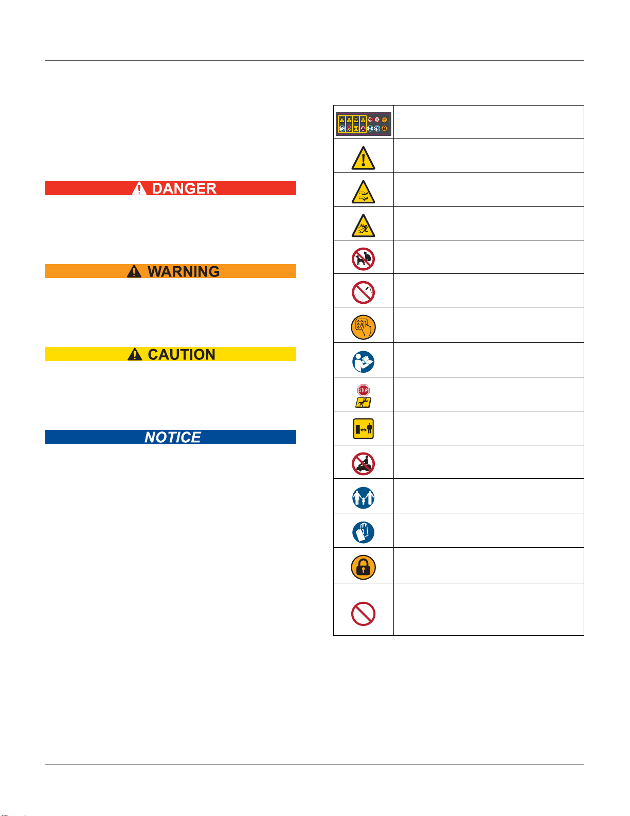
The safety alert symbol accompanied by the word
“DANGER” calls attention to an act or condition which
WILL lead to serious personal injury or death if not
avoided.
The safety alert symbol accompanied by the word
“WARNING” calls attention to an act or condition
which CAN lead to serious personal injury or death if
not avoided.
The safety alert symbol accompanied by the word
“CAUTION” calls attention to an act or condition which
may lead to minor or moderate personal injury if not
avoided.
The enclosed message provides information necessary
for the protection of the unit.
Safety Symbols
Safety and Information Label
Caution: The robot can be dangerous if misused.
Never place hands or feet under the robot while
it is powered ON.
Beware of projectiles.
Keep animals away from the robot.
Water cleaning with high pressure jet systems
can cause damage.
The robot is protected by an access code.
Read the technical manual before using the
robot.
Press the STOP button and wait for the cutting
disc to stop rotation before handling the robot.
Always keep a safe distance from the robot when
is it powered ON and the cutting discs are
rotating.
Do not ride on the robot.
Keep bystanders away from the robot.
Wear protective gloves when handling the robot.
The robot is equipped with an anti‐theft system.
General Prohibition Symbol
This symbol means the specific action shown is
prohibited. Ignoring this symbol can result in
damage to property and serious or fatal injury.