TCL 55D1620 User manual

Product Type LCD Smart TV Music MP3, AC3, HE-AAC, LPCM
Chassis MT56-LA(MT56B.01) Picture JPEG, PNG, BMP, MPO
CPU Quad core CPU ARM CA7,920MHz MPEG2, MPEG4, H.264,Motion•JPEG
GPU ---
OS Linux
Memory 1G DDR +4G EMMC File ---
OSD Language English/Spanish/Portuguese
ATV: NTSC-M, PAL-M/N
DTV: ISDB-T Component Video Format ---
AV System PAL,NTSC DVI Video Format Up to XGA for HDMI-PC
TV Channels (Air)
ATV:2~69, DTV:7~69 HDMI Video Format Up to 1080P
TV Channels (Cable) 1~135 PC Compatibility ---
Power Supply AC 110V-240V 50/60Hz
Power Consumption(TV On)
Power Consumption(Standby)≤0.5W Backlight Unit DLED
Certification CB Panel supplier CSOT
Wired Network Default Aspect Ratio 16:9
Built in wireless(802.11 b/g/n 2x2) Panel Size (inch) 55"
Wake-on-LAN Yes Display Resolution 1920×1080
Brightness (cd/m2)(typ.) 260
Contrast Ratio 4000:1
Response Time (G to G) 8ms
Auto Source --- Viewing Angle (H/V) 178°/178°
EPG Yes(at DTV) Life Time(Typ.)
>30,000hrs
Subtitle/Closed Caption Yes Color 16.7M
Parental Control Yes (at DTV) Refresh Rate 60Hz
Sleep Timer Yes
System Update Yes
Hotel Mode --- HDMI 3
Input Method Virtual keyboard USB 2
MHL --- AV in 1
Lightsensor --- YPbPr in No
GINGA Yes AUDIO out 1(R/L)
HDMI
HDMI with CEC、MHL2.0 、ARC VGA in No
--- VGA audio in No
--- RJ45 1
--- SPDIF out 1
--- Earphone out 1
MHL share with HDMI
RF Input 1
DCC(Dynamic Contrast Control)Yes
Backlight Adjustable Yes (0~100)
Color Temperature Normal/Cold/Warm
Picture Mode Vivid, Normal, Mild, User
Picture Size
Auto、16:9、4:3、Just Scan
Picture enhancement technology On/Off
Speakers Integrated speakers (Bottom side)
Audio Power Output (THD=7%) 2×8W
Auto Volume Yes
Sound Mode Standard/Movie/Music/Clear voice/Personal
Sound Control Balance
Frequency range Equalizer
Terminals
Panel Specification
Internet Link
Video
Basic Function
PRODUCT SPECIFICATION RELEASE
Model: 55D1620/MT5655-LA
Version:1.0 Issued On: 2016-06-07
Signal Format Capability
TV System
Basic Information
Media Format
Picture
Sound

Essential Accessories (Default)
NetFlix Yes Operation Manual English (Default)
Youtube Yes Remote Control RC311
Golive3.0 Yes Base Stand Integrated Packaging
Browser Yes AC power cord 1 pcs
Crackle Yes
icflix No
Foxxum Yes
Deezer Yes Wall Mount WMB333
Dailymotion Yes WI-FI
---
Others
WeatherNation(Argentina&Mexico)
Babbidiboo(Brazil),Hellokids(others)
Batteries 2 pcs
Wireless Display Yes
File Share Yes
Diagonal size(cm)138.8 L1(mm)1249.0
Slim Edge Design---Up(mm)17.5 W1(mm)88.1
Slim Edge Design---Bottom(mm)25.9 H1(mm)740.0
Slim Edge Design---L&R(mm)17.5 L2(mm)982.0
Carton Dimensions LxWxH(mm)
1400*160*856 W2(mm)248.3
Container Loading---20 feet(pcs)114 H2(mm)778.6
Container Loading---40 feet(pcs)234 Net Weight With Stand(Kg)13.8kg
Container Loading--40 feet High (pcs) 351 Net Weight Without Stand (Kg) 13.6kg
VESA Mounting Dimensions LxH(mm)400x400 Gross Weight With Packaging(Kg)18.0kg
Design and specifications are subject to change without notice!
Drafted by: Approved by:
Mechanical ID Picture
Optional Accessories
Pre-Installed Application List
Mechanical Key Specification
L1

Factory Test & Alignment Specification For MT56 Series (V1.0)
1
World-Wide R&D
FPD CENTER
Factory Test & Alignment Specification V1.0
----MT56
PREPARED BY : FENG LIU DATE : 2015-02-13
APPROVED BY: DATE :

Factory Test & Alignment Specification For MT56 Series (V1.0)
2
Content
1. General Description.............................................................................................................................. 3
2. Factory Menu......................................................................................................................................... 5
2.1 Accessing Way................................................................................................................................... 5
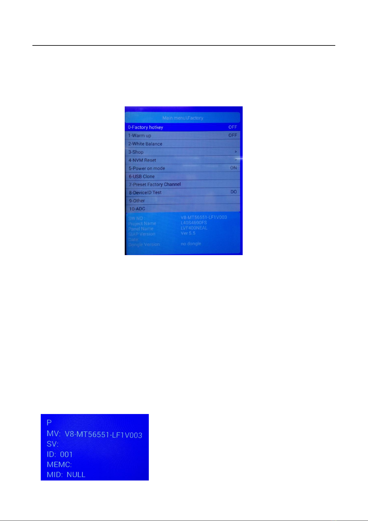
2.2 Factory Menu...................................................................................................................................... 6
2.3 White Balance Menu.......................................................................................................................... 7
3. Design Menu.......................................................................................................................................... 7
3.1 Accessing Way................................................................................................................................... 8
3.2 Design Menu....................................................................................................................................... 8
3.3 Other Menu......................................................................................................................................... 9
3.4 Service Menu...................................................................................................................................... 9
3.5 Param Setting Menu........................................................................................................................ 10
4. Test & Alignment................................................................................................................................. 11
4.1 Pre-Conditions and Power Supply Check.................................................................................... 11
4.2 Project ID Modification .................................................................................................................... 11
4.3 Function Test.................................................................................................................................... 12
4.4 LAN/WLAN Test............................................................................................................................... 13
4.5 SHOP INIT ........................................................................................................................................ 13
Appendix...................................................................................................................................................... 14
Appendix 1: Warm-up Test.................................................................................................................... 14
Appendix 2: Software Upgrade............................................................................................................. 15
Appendix 3: Network Connection......................................................................................................... 17
Appendix 4: White Balance (WB) Adjustment.................................................................................... 18

Factory Test & Alignment Specification For MT56 Series (V1.0)
3
1. General Description
The information contained in this document is proprietary to TCL SZ FPD lab and shall
not be disclosed by the recipient to the third person without the written permission of
the team leader or GM of R&D.
MT56-AP chassis are designed for Asia & Pacific (AP) market Ready for Smart TV. It
features by its high integration, easy debugging (ADC adjustment free) as well as
convenience in terms of maintenance. Fast software upgrade through USB disk
facilitates both manufacture and after-sale service. Meantime, a variety of functions
involved in Factory Main Menu can not only bring benefits for production, but also
satisfy various demands of customers.
Note: Factory Main Menu (FMM) is divided into Factory menu and Design menu. Factory
Menu covers all indispensable functions during manufacture such as White Balance
Adjustment, SHOP etc., while Design Menu includes Service Menu, Hotel Menu, Param
Setting, Other Setting etc. Some settings like Param Setting and Other Setting is exclusively
used by R&D engineer, anyone else shouldn’t change the settings in the menu. When you
wish to learn the product information like project ID, project name, Hardware, software
version, release date, you can access to Service Menu. In addition, in Hotel Menu, we also
provide a great deal of useful functions for specific applications in hotel.
The main chip is from REALTEK and supports below features matrix:
Class
Item
MT56-AP
Input
&
Output
RF Input
(PAL/DVB/DVB-T2)
CABLE&ANTENNA
HDMI
(480i/p, 576i/p, 720p up to 1080i/p, with
HDCP)
HDMI*3
VGA
1
VGA Audio
Shares audio sockets withAudio Input
Component Audio Input
RCA*2 (L+R)
AV Input
RCA*1

Factory Test & Alignment Specification For MT56 Series (V1.0)
4
Input
&
Output
Audio Out
RCA*2
USB
(Video, audio and picture)
USB2.0*2
MHL
Shares with HDMI 1
PCMCIA
1
SPDIF output
RCA*1
NETWORK
RJ45 Socket
Functions
Internet
WIFI
Others
Serial connector
Multiplexing VGA
IC Details
&
Position
Main program
UF01
(Support online upgrade)
Mboot
UF01
(Support online upgrade)
EEPROM
U702
Note:
The software boot for U702 can be programed by Flash Tool.exe.
Every set has its unique HDCP key which is purchased from suppliers or HDCP
certification authority. Please check HDCP function in the process of production.
Once in a while, the software of main board may be upgraded. Please pay attention to
use the latest software before production.

Factory Test & Alignment Specification For MT56 Series (V1.0)
5
2. Factory Menu
Factory Menu is mainly used for factory production and satisfies various demands of customers. It covers
all indispensable functions during manufacture such as Warm up, White Balance, Shop, NVM Reset,
Power on mode, USB Clone etc.
2.1 Accessing Way
a. When the Factory hotkey item of Factory Menu is disabled (OFF), press Menu button of remote
control, then select Settings/Picture, make sure the cursor stop on Contrast item submenu. Finally,
press 9, 7, 3, 5consecutively.
b. When the Factory hotkey item of Factory Menu is enabled (ON,you can see the flashing Factory
Captions Info on the lower left corner), press Back button of remote control.
Press RCU “OK” key to enter the submenu.
Press RCU “Right” or “Left” key to change the values.
Press RCU “Right” or “Left” key run the function.
Press RCU “Back” or “Menu” key exit the Factory menu.
Factory Captions Info:
While “FactoryKey” is enabled, there is some toggled display information relative to MV, SV, ID, MID, to
facilitate 100% quick screening without accessing to whatever else menu:
P (Production/Factory mode flag)
MV (Mboot SW Version)
SV (Main SW Version)
ID (Project ID)
MEMC

Factory Test & Alignment Specification For MT56 Series (V1.0)
6
MID
2.2 Factory Menu
Factory Menu
Name
Default
Description
Factory hotkey
OFF
Factory Menu shortcut button switch
The item must be disabled (OFF) after production
Warm up
OFF
Aging mode, mainly used for factory aging.
Press “Menu” key on keyboard to exit the burning mode.
See Appendix 1 “Warm-up Test”
White Balance
..
White Balance Adjustment ( see details below)
Shop
>
It is crucial that the function is executed after production aim to clear information
of production process, ensure user cannot access to Factory Menu after
executing the item.
NVM Reset
>
Restore default value except White Balance, ADC data.
Power On Mode
STANDBY
ON: the set will power on after switching on power.
STANDBY: the set will remain standby status after switching on power.
LAST: the set will turn to the status in which it lies when last switching off.
If without requirement from certain customer, by default, the Setting should be
STANDBY
USB Clone
..
Select to choose the things you want to clone.
Preset Factory
Channel
..
Preset the channel table of factory. To preset the channel table of certain factory,
first, choose the corresponding factory name. Then press OK button of remote
control and wait OK is displayed on the screen.
DeviceID test
DO
Test device ID.
Other
Project Information
ADC
..
Analog To Digital Converter
SW NO.
device info
Version information of Main Software
Project Name
device info
Product model
Date
device info
Release date and time of main software

Factory Test & Alignment Specification For MT56 Series (V1.0)
7
2.3 White Balance Menu
Press the button on remote control to select certain item and OK to adjust White Balance.
3. Design Menu
Design Menu includes Factory Menu, other,
Service Menu, Param Setting, Hotel Menu.
Some settings like Param Setting and Other
Menu is exclusively used by R&D engineer,
anyone else shouldn’t change the settings in the
menu. When you wish to learn the product
information like project ID, project name, chassis
name, software version, release date, you can
access to Service Menu. In addition, in Hotel
Menu, we also provide a great deal of useful
functions for specific applications in hotel.
White Balance
Name
Default
Description
Source
ATV
Press RCU left/right key to change the TV source.
Color
normal
Select color temperature you intend to adjust Three groups of color
temperature: normal, Cold, Warm are available.
R gain
0-255
Gain of R channel ( cannot be changed after auto calibration)
G gain
0-255
Gain of G channel ( cannot be changed after auto calibration)
B gain
0-255
Gain of B channel ( cannot be changed after auto calibration)
R offset
128
Disabled, keep the default value
G offset
128
Disabled, keep the default value
B offset
128
Disabled, keep the default value
White Balance
init
>
White Balance Initalization. Before WB adjustment, this item should be
executed.

Factory Test & Alignment Specification For MT56 Series (V1.0)
8
3.1 Accessing Way
a. When the Design mode hotkey item is disabled(OFF), press Menu button of remote
control, then select Settings/ Picture, make sure the cursor stop on Contrast item
submenu, press 1, 9, 5, 0consecutively.
b. When the Design mode hotkey item of Design Menu is enabled (ON,you can see the
flashing Factory Captions Info on the lower left corner), press Back button of remote
control.
Press RCU OK key to enter the submenu.
Press RCU Right/Left key to change the values.
Press RCU Right/Left key run the function.
Press RCU Back/Menu key exit the Factory menu.
Design Captions Information is the same to Factory Captions Info.
3.2 Design Menu
Design Menu
Name
Default
Description
Design Mode
hotkey
OFF
Design Menu shortcut button switch
The item must be disabled (OFF) after production
Factory menu
..
Access to Factory Menu
Other
..
The item includes a number of functions offering convenience for R&D engineer
to solve problems.
Service menu
..
Provide many useful information for after-sale service
Please reference to SERVICE MENU submenu
Param setting
..
Include sound setting,picture setting, SSC, DBC, CI Card, Overscan, WIFI
CHECK and USB FILE. Please reference to PARAM SETTING submenu.
Hotel menu
..
Include special functions which bring benefits to hotel management. The item is
accessible only when Hotel Service On/Off item is enabled (ON).

Factory Test & Alignment Specification For MT56 Series (V1.0)
9
3.3 Other Menu
The Other Menu contains some TV basic information, with which we can check the TV setting before
production.
3.4 Service Menu
Service Menu contains some basic information of the device, such as Project ID, Hardware, Software
version, USB Update etc. This menu is especially useful for after-sale service.
Other Menu
Name
Default
Description
TestPattern
>
Switch the TV source into test pattern, and restarting TV is the only way to excit.
UartEnable
OFF
The switch of VGA serial port information.
The item must be disabled (OFF) after production.
DeviceID
..
Show the device id of TV.
MAC
..
Show the MAC address of TV.
HuanID
..
Show the Huan id of TV.
ClientType
..
Show the Client type information.
Service Menu
Name
Default
Description
Project ID
1
Select project parameters, depending on the BOM description.
Hardware
MT5655
mainboard Chassis
Software
V8-MT56551-LF1V003
version number of Main Software
Bootloader
XXX
version number of bootcore
USB Update
..
Update the software by USB disk,
detailed description see Appendix 2 “Software Update”

Factory Test & Alignment Specification For MT56 Series (V1.0)
10
3.5 Param Setting Menu
Param Setting menu contains Sound Setting, Picture Curve, Picture Setting, SSC, DBC, CI Card,
Overscan, WIFI CHECK and USB FILE. But it is exclusively used by R&D engineer, anyone else shouldn’t
change the settings in the menu.
Param setting Menu
Name
Default
Description
Sound Setting
..
Set sound mode, balance, sound scene, etc.
Picture Curve
..
Exclusively used by R&D
Picture Setting
..
Set picture mode, brightness, contrast, backlight, etc.
SSC Adjust
..
Spread Spectrum clocking.
Exclusively used by R&D.
DBC
..
Dynamic Backlight Control.
Exclusively used by R&D.
CI Card
ON
Common interface Card switch.
WIFI CHEAK
..
Check the WIFI link
USB FILE
..
Access the USB file

Factory Test & Alignment Specification For MT56 Series (V1.0)
11
4. Test & Alignment
According to the requirement of order, we suggest take the below steps to finish the appropriate settings.
Note:
All tests and measurements mentioned hereafter have to be carried out at a normal mains voltage
(100 ~ 240 VAC)
All voltages have to be measured with respect to ground, unless otherwise stated
All final tests have to be done on a complete set including LCD panel in a room with temperature of
25+/-7°C
The Picture Performance assessment such as White Balance (luminance and colour temperature)
has to be performed into subdued lighted room after at least 60min of warm-up in order to avoid any
temperature drift influence (colorimetry vs time).
4.1 Pre-Conditions and Power Supply Check
Before power-on, please check the board according to the relevant block diagram and circuit diagram,
make sure that no serious issue or mistake can destroy the board. For example, the output of DC/DC and
LDO should not be shorted to ground.
Supply a suited voltage and power-on, then check the voltage according to the relevant block diagram,
circuit diagram and voltage spec, the error should be less than 5%, for example, the voltage for main chip
(+3V3, +2.5V, VDDC1V15, 1V5_DDR, etc.), the voltage for TUNER (TU_3V3), the voltage for amplifier
(AMP_VCC), etc.
4.2 Project ID Modification
There are different ID stored in the EMMC depending on different Panels settings and Model features, but
there’s only one key branching Project ID able to ensure normal display. And when you power on the TV
set, you should make sure the Project ID is accord with the BOM description. If not, you need to modify
Position
Value
Test Point
P103
12V±10%
12V
LDH1
5V±5%
+5V
P103
3.3V ±1%
3V3SB
UD33
3.3V ±1%
3V3
LDJ1
1.5V ±1%
DDR_1V5
LDB0
1.2V±1%
CORE_1V2
UD18
1.8V ±1%
1V8
UT2
3.3V ±1%
TUNER_VCC
U201
3.3V ±1%
3V3_DEMO
L201
1.1V ±1%
NC

Factory Test & Alignment Specification For MT56 Series (V1.0)
12
the ID. There are two methods to modify the ID:
Change Project ID in Design Menu
In case of “Design mode hotkey” is enabled, press “Back”button to enter Design Menu. To modify
Project ID, you need to go through “Service menuProject ID”, then press Left or Right key to
select suitable ID (Project name is dynamically refreshed). Finally restart the TV set.
In case of “Design mode hotkey” is unabled, you can enter the Design Menu easily with reference
to 3.1 Design Menu.
Change Project ID with RCU
Press “062598”+”Menu”+”XXX” (XXX represents project ID you’d like to switch to) in the remote
control and wait about half minutes, When the set restart automatically, you have successfully
changed project ID.
Here below is none exhaustive ProjectID table for reference:
MODEL
ProjectID
Panel Name
L40S4690FS
001
LVF400NEAL
4.3 Function Test
Once the Project ID is correct and the TV display normally, plug all external generator devices to relevant
inputs/outputs below according to their respective test patterns format and check picture content and
sound quality accordingly:
Source
Test Signal
Test Pattern
RF Input
(PAL/DVB/DVB-T2)
RF cable
Factory signal
AV
(CVBS)
Chroma/Fluke generator
PAL Half Color & Gray bars
VGA
Chroma/QuantumData
generator
1024x768@60Hz
Half Color & Gray bars
HDMI
(Video & Audio)
DVD with HDMI compliancy
Movie 720p@60Hz
LAN
(RJ45)
Ethernet
Any network
Audio OUT
RF signal
Suitable channel
USB
Video/MP3/Image
Home/Media/
SPDIF
DOSS
Audio output
PCMCIA
TV source
Suitbale PCMCIA Card

Factory Test & Alignment Specification For MT56 Series (V1.0)
13
4.4 LAN/WLAN Test
MAC Address Upgrade
Upgrading MAC address needs to use the tool in factory and through serial command. The specific
method is according to the operation of the factory guidance.
DeviceID (DID) and UserID (UID)
Purpose is to allow Other Network Download (OND) and further specific services over dedicated portal
based on AP. For such, specific DID (32 bytes) and UID (8 bytes) needs to be paired and overwritten into
memory for internal client encryption,as below:
Device ID
User ID
2bbf5dec37068855003ef54b9e27f3be68118899
3546187
Those DID/UID codes can only be set using UART commands following enclosed SIACP requirements
(rev. v3.9).
LAN Test
A rough LAN test can be done by connecting Ethernet to TV’s RJ45 and check that IP, subnet mask, DNS
addresses, which are visible on “HomeSettingsNetworkEthernet settingsIP settings” (ensure
that “Internet Connection” is Enabled at first). More in-depth test can be performed faster using suitable
UART/IR commands following SIACP requirements. SW will internally manage Network ID (NID) flag
controlling all MAC/DID/UID integrity to facilitate PA screening further.
See Appendix 3 “Network Connection”
4.5 SHOP INIT
At final process stage, it’s necessary to perform Shop init before any packing to leave Factory mode and
restore User default presets according to the requirement of order.
This function is accessible by selecting “Factory MenuShop”, then pressing RCU “Right ”or” Left”key.
Other faster methods are available on above enclosed SIACP requirements (rev. v3.9).

Factory Test & Alignment Specification For MT56 Series (V1.0)
14
Appendix
Appendix 1: Warm-up Test
Following TCL standard and practices, it’s required minimum 15min of Warm-Up that can be considered
as Burn-In.Additional aging for White Balance alignment is no more necessary due to consistent picture
performance with cloning usage. This function is accessible by selecting “Factory menu Warm up”,
pressing RCU “Right” or ”Left” key to set it ON, and then it enter in Warm up mode. Press “Menu” key on
keyboard to exit the burning mode. Other faster methods are available on above enclosed SIACP
requirements (rev. v3.9).

Factory Test & Alignment Specification For MT56 Series (V1.0)
15
Appendix 2: Software Upgrade
How to upgrade Mboot
Connect the computer and mainboard VGAport by a serial port tool.
Serial connector definition: VGA/P303: Pin4: RXD VGA Pin11:TXD
Open MTK “Mboot” software programming tool “Flash Tool”, and set serial port.
Import the mboot file, as below.
power on the TV, then Click Upgrade key and you will see the below message.

Factory Test & Alignment Specification For MT56 Series (V1.0)
16
How to upgrade FLASH Software
1. USB Upgrade
Download the update file (generally named V8-MT56551-LF1VXXX.pkg) to the root directory of your
USB device, and make sure there’s no other bin file named analogously. Then insert the USB device
to USB interface of TV set.
Power on the TV set, Press and hold on the menu key of key board at the same time. If the TV is
updating, you’ll see the below screen:
Upgrade process takes about 3~5 minutes.
After updating, the TV set will reset automatically.
2. Online Upgrade
Download the bin zip file “V8-MT56551-LF1VXXX.Zip” to the root directory of your USB device, and
do not change the file name. Then insert the USB device to USB interface of TV set.
Press RCU Menu/Settings/Picture/Contrast/1,9,5,0/Service menu/USB Update /Main
Upgrade/Local Update . If the upgrade file is found, TV will give a message that it verifying. TV
displays a warning message, it means selecting “confirm” to continue or “cancel” to exit. During
updating, do not power off the TV set.
After updating, the TV set will reset automatically.

Factory Test & Alignment Specification For MT56 Series (V1.0)
17
Appendix 3: Network Connection
You can set up your TV so that it can access the Internet through your local area network (LAN) using a
wired or wireless connection.
Connect to a wired network
Attach the TV set to your LAN using cable in three ways:
Connecting the LAN port on the TV to an external modem using a Cat 5 cable.
Connecting the LAN port on the TV to an IP Sharer which is connected to an external modem. Use
Cat 5 cable for the connection.
Depending on how your network is configured, you may be able to attach the TV to your LAN by
connecting the LAN port on your TV directly to a network wall outlet using a network cable. Note that
the wall outlet is attached to a modem or router anywhere in your house.
Select Home→Settings→Network →Ethernet Settings→IP Settings, then the TV will obtain IP
address Automatic configuration. In addition, you can set the IP address and password manually.
Connecting to a wireless network
To connect the TV set to your network wirelessly, you need a wireless router or modem and a Wireless
LAN Adapter.
If the TV set is equiped with an internal WiFi module, select Home→Settings→Network→Wireless
Settings, then turn on Wireless Switch, select a wireless network and press OK to connect.
If you want to connect the TV set to a wireless network by a Wireless High Gain USB Adapter (USB
dongle), select Home→Settings→Network→Wireless Settings, then turn on Wireless Switch and
External WiFi, and select a wireless network and press OK to connect.

Factory Test & Alignment Specification For MT56 Series (V1.0)
18
Appendix 4: White Balance (WB) Adjustment
The White Balance generally is customized by PQ engineer, and uploaded to the PDM system, anyone
else shouldn’t change the value in the menu. If it is necessary to adjust, the following content can offer
some reference, but the process of adjusting White Balance is out of the range of this file. Please refer to
the relevant technical file of HuiZhou factory of TCL.
Calibration of Color Temperature
According to TCL standards, the color temperature and white reference coordinates of LCD like the
following table: (This standard is based on CA-310 color temperature meter)
Product
type
Color
temperature
state
Color
temperature
chromaticity coordinate
tolerance
(X,Y)
X
Y
LCD
cold
13000K
0.270
0.270
±0.015
normal
10000K
0.280
0.290
warm
7500K
0.300
0.305
White balance adjustment takes the Normal color temperature of HDMI channel as the reference.
Warm and Cold tone is relative to Normal mode. The adjustable gain range is 0~255.
The Normal color temperature of other channel is relative to the Normal mode of HDMI channel. The
adjustable gain range is also 0~255.
The manual adjustment is according to the regulation above. Additionally, when manually adjust, it
needs to do White Balance init first.
Take signal generator 22293 as an example, the timing value and pattern value of each source show in
the following table:
source
HDMI
VGA
AV/ATV
CMP
Timing value
69
14
38
79
Pattern value
103
103
103
103
Note: 1) The input signal is 80% white when the pattern value of 22293 is 103.
2) The adjustment of White Balance should fulfill TCLmatching specification.
This manual suits for next models
1
Table of contents
Other TCL TV manuals