TCM MMCUT18AS2 User manual
1
Multi outdoor units
sErViCE MAnuAl Multi zone
CondEnsinG units
Revision E: ODMFI-E-1705
Model Numbers:
MMCUT18AS2 MMCUT27AS3 MMCUT36AS4
MMCUT48AS5
WARNING
•Installation MUST conform with local building codes or, in the absence of local
codes, with the National Electrical Code NFPA70/ANSI C1-1993 or current edition
and Canadian Electrical Code Part1 CSA C.22.1.
•The information contained in the manual is intended for use by a qualified service
technician familiar with safety procedures and equipped with the proper tools and
test instruments
•Installation or repairs made by unqualified persons can result in hazards to you
and others.
•Failure to carefully read and follow all instructions in this manual can result in
equipment malfunction, property damage, personal injury and/or death.
Table of Contents
1. Indoor Unit Combination
2. Dimension Of Outdoor Unit
3. Refrigerant Cycle Diagram
4. Installation Details
5. Electronic Function
6. Wiring Diagrams
7. Trouble Shooting
8. Disassembly Instructions

2
CONTENTS
1. Indoor Unit Combination.......................................................................................................................................... 4
2. Dimension Of Outdoor Unit...................................................................................................................................... 6
3. Refrigerant Cycle Diagram........................................................................................................................................ 8
4. Installation Details ..................................................................................................................................................11
4.1 Wrench torque sheet for installation ............................................................................................................... 11
4.2 Connecting the cables ...................................................................................................................................... 11
4.3 Pipe length and the elevation........................................................................................................................... 11
4.4 First-Time Installation....................................................................................................................................... 11
4.5 Adding Refrigerant after Long-Term System Operation...................................................................................13
4.6 Procedure when servicing the indoor unit refrigeration circuit.......................................................................13
4.7 Evacuation after servicing the outdoor unit refrigeration circuit ....................................................................14
5. Electronic Function.................................................................................................................................................16
5.1 Abbreviation ..................................................................................................................................................... 16
5.2 Electric Control Working Environment............................................................................................................. 16
5.3 Main Protection................................................................................................................................................16
5.4 Control and Functions ...................................................................................................................................... 18
6. Wiring Diagrams .....................................................................................................................................................23
7. Troubleshooting ..................................................................................................................................................... 30
7.1Safety................................................................................................................................................................. 30
7.2Indoor Unit Error Display...................................................................................................................................31
7.3 Outdoor Unit Display ........................................................................................................................................ 34
7.4 Diagnosis and Solution .....................................................................................................................................39
7.5 Trouble Criterion of Main Parts........................................................................................................................ 88
8. Disassembly Instructions ........................................................................................................................................ 99
MMCUT18AS2 (WCA30 metal plate)...................................................................................................99
MMCUT27AS3 (WD30 metal plate)....................................................................................................106


4
1. Indoor Unit Combination
Multi DC
Outdoor Unit Nominal
capacity Suggested
Combination Limit
1drive 2 5.2kW
12
None
9+9
9+12
12+12
Multi DC
Outdoor Unit Nominal
capacity Suggested
Combination Limit
1 drive 5 14kW
18+18
None
18+24
24+24
9+9+18
9+9+24
9+12+12
9+12+18
9+12+24
9+18+18
9+18+24
9+24+24
12+12+12
12+12+18
12+12+24
12+18+18
12+18+24
12+24+24
18+18+18
Multi DC
Outdoor Unit Nominal
capacity Suggested
Combination Limit
1drive 3 7.8kW
9+9
None
9+12
9+18
12+12
12+18
18+18
9+9+9
9+9+12
9+9+18
9+12+12
9+12+18
12+12+12
Multi DC
Outdoor Unit Nominal
capacity Suggested
Combination Limit
1 drive 4 10.5kW
9+18
None
12+12
12+18
18+18
9+9+9
9+9+12
9+9+18
9+12+12
9+12+18
9+18+18
12+12+12
12+12+18
12+18+18
9+9+9+9
9+9+9+12
9+9+9+18
9+9+12+12
9+9+12+18
9+12+12+12
12+12+12+12

5
18+18+24
9+9+9+9
9+9+9+12
9+9+9+18
9+9+9+24
9+9+12+12
9+9+12+18
9+9+12+24
9+9+18+18
9+9+18+24
9+12+12+12
9+12+12+18
9+12+12+24
9+12+18+18
9+18+18+18
12+12+12+12
12+12+12+18
12+12+12+24
12+12+18+18
9+9+9+9+9
9+9+9+9+12
9+9+9+9+18
9+9+9+9+24
9+9+9+12+12
9+9+9+12+18
9+9+9+18+18
9+9+12+12+12
9+9+12+12+18
9+12+12+12+12
9+12+12+12+18
12+12+12+12+12
6
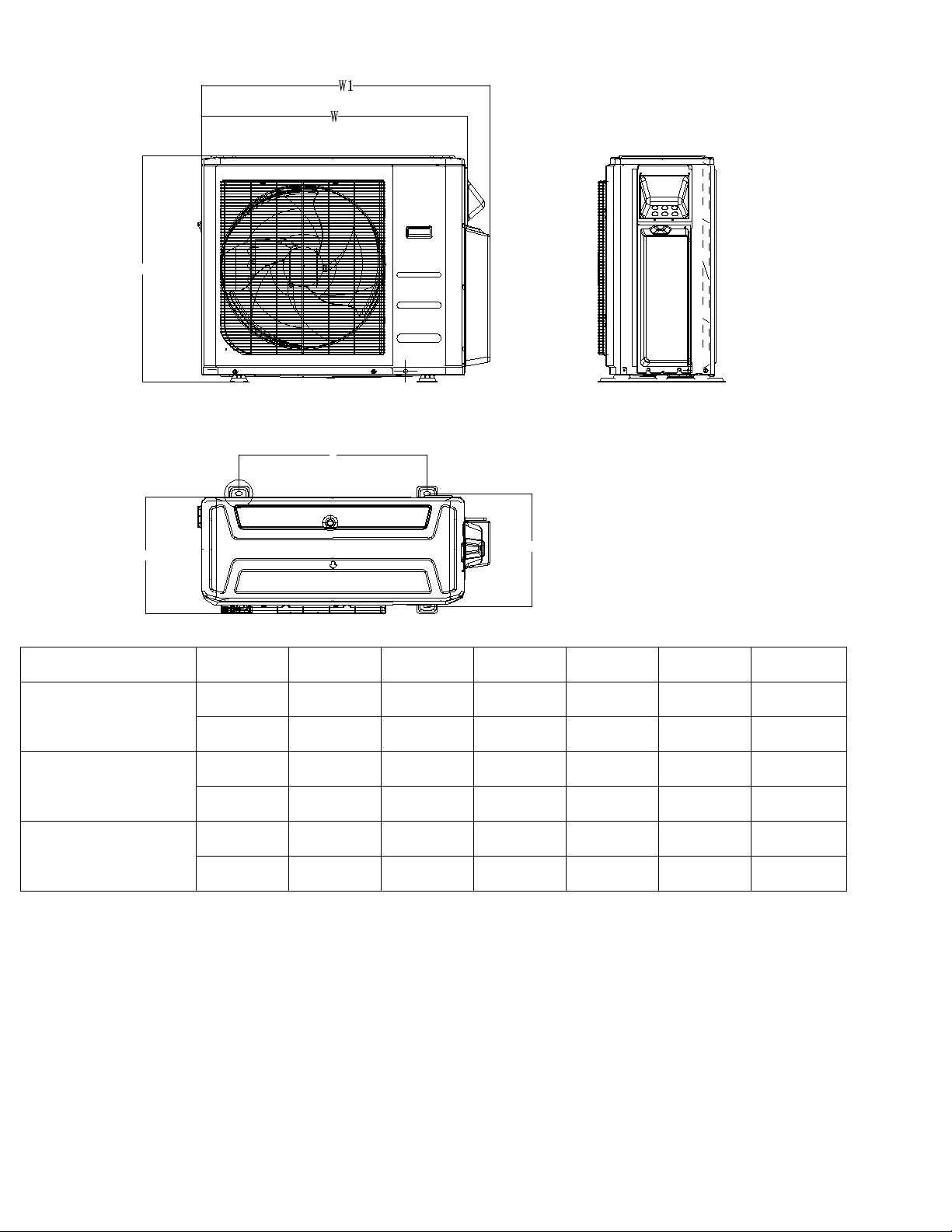
2. Dimension Of Outdoor Unit
H
D
A
B
Model
Unit:
W
D
H
W1
A
B
MMCUT18AS2
mm
845 363 702 923 540 350
inch
33.3
14.3
27.6
36.0
21.3
13.8
MMCUT27AS3
mm
946
410
810
1034
673
403
inch
37.2
16.5
31.9
40.6
26.5
15.9
MMCUT36AS4
mm
946
410
810
1034
673
403
inch
37.2
16.5
31.9
40.6
26.5
15.9

7
H
W
A
D
W1
B
Model
Unit:
W
D
H
W1
A
B
MMCUT48AS5
mm
952
415
1333
1060
634
404
inch
37.5
16.3
52.5
41.7
25.0
15.9

8
3. Refrigerant Cycle Diagram
3.1 Refrigeration circuit drawing of inverter 1 drive 2 type
LIQUID VALVE A
GAS VALVE A
HEAT
EXCHANGE
(EVAPORATOR) HEAT
EXCHANGE
(CONDENSER)
Compressor
4-WAY VALVE
COOLING
HEATING
T2 Evaporator
temp. sensor
middle
T1 Room
temp. sensor
T3
Condenser
temp. sensor
T5 Discharge
temp. sensor
T4 Ambient
temp. sensor
INDOOR OUTDOOR
EXV A CAPILLARY A
CHECK VALVE
CAPILLARY TUBE
EXV B CAPILLARY B
LIQUID VALVE B
GAS VALVE B
Accumulator
T2B-A
Evaporator
temp. sensor outlet
T2B-B
3.2 Refrigeration circuit drawing of inverter 1 drive 3 type
LIQUID VALVE A
GAS VALVE A
HEAT
EXCHANGE
(EVAPORATOR) HEAT
EXCHANGE
(CONDENSER)
Compressor
4-WAY VALVE
COOLING
HEATING
T2 Evaporator
temp. sensor
middle
T1 Room
temp. sensor
T3
Condenser
temp. sensor
T5 Discharge
temp. sensor
T4 Ambient
temp. sensor
INDOOR OUTDOOR
EXV A CAPILLARY A
CHECK VALVE
CAPILLARY TUBE
EXV B CAPILLARY B
LIQUID VALVE B
GAS VALVE B
EXV C CAPILLARY C
LIQUID VALVE C
GAS VALVE C Accumulator
T2B-A
Evaporator
temp. sensor outlet
T2B-B
T2B-C

9
3.3 Refrigeration circuit drawing of inverter 1 drive 4 type
LIQUID VALVE A
GAS VALVE A
HEAT
EXCHANGE
(EVAPORATOR) HEAT
EXCHANGE
(CONDENSER)
Compressor
4-WAY VALVE
COOLING
HEATING
T2 Evaporator
temp. sensor
middle
T1 Room
temp. sensor
T3
Condenser
temp. sensor
T5 Discharge
temp. sensor
T4 Ambient
temp. sensor
INDOOR OUTDOOR
EXV A CAPILLARY A
CHECK VALVE
CAPILLARY TUBE
EXV B CAPILLARY B
LIQUID VALVE B
GAS VALVE B
EXV C CAPILLARY C
LIQUID VALVE C
GAS VALVE C
EXV D CAPILLARY D
LIQUID VALVE D
GAS VALVE D
Accumulator High pressure
switch
Low pressure
switch
T2B-A Evaporator
temp. sensor outlet
T2B-B
T2B-C
T2B-D
3.4 Refrigeration circuit drawing of inverter 1 drive 5 type
LIQUID VALVE A
GAS VALVE A
HEAT
EXCHANGE
(EVAPORATOR) HEAT
EXCHANGE
(CONDENSER)
COOLING
HEATING
T2 Evaporator
temp. sensor
T1 Room
temp. sensor
T3
Condenser
temp. sensor
T4 Ambient
temp. sensor
INDOOR OUTDOOR
EXV A CAPILLARY A
CHECK VALVE
CAPILLARY TUBE
EXV B CAPILLARY B
LIQUID VALVE B
GAS VALVE B
EXV C CAPILLARY C
LIQUID VALVE C
GAS VALVE C
EXV D CAPILLARY D
LIQUID VALVE D
GAS VALVE D
EXV E CAPILLARY E
LIQUID VALVE E
GAS VALVE E Compressor
4-WAY VALVE
T5 Discharge
temp. sensor
Accumulator High pressure
switch
Low pressure
switch
T2B-A Evaporator
temp. sensor outlet
T2B-B
T2B-C
T2B-D
T2B-E

10

11
4. Installation Details
4.1 Wrench torque sheet for installation
Outside diameter Torque Additional tightening torque
mm inch N.cm N.cm
Ф6.35 1/4 1500(153kgf.cm) 1600(163kgf.cm)
Ф9.52 3/8 2500(255kgf.cm) 2600(265kgf.cm)
Ф12.7 1/2 3500(357kgf.cm) 3600(367kgf.cm)
4.2 Connecting the cables
The power cord connection should be
selected according to the following
specifications sheet.
Unit AWG
1 drive 2 type (18K outdoor unit) 14
1 drive 3 type (27K outdoor unit). 14
1 drive 4 type (36K outdoor unit) 12
1 drive 5 type (48K outdoor unit) 10
For indoor unit and outdoor unit connection
line, 16AWG is ok for all.
4.3 Pipe length and the elevation
Maximum piping length and height difference
1 drive 2
1 drive 3
1 drive 4
1 drive 5
Max. length for all
rooms (m)
40
(131ft)
60
(197ft)
80
(262ft)
80
(262ft)
Max. length for
one IU (m)
25 (82ft) 30 (98ft)
35
(115ft)
35
(115ft)
Max. height
difference between
IU and OU (m)
15
(49.2ft) 15
(49.2ft) 15
(49.2ft) 15
(49.2ft)
Max. height
difference between
IUs (m)
10 (33ft) 10 (33ft) 10 (33ft) 10 (33ft)
Additional refrigerant charge
1 drive 2
1 drive 3
1 drive 4
1 drive 5
Pre-charge pipe
length (m)
15
(49.2ft)
22.5
(73.8ft)
30
(98.4ft)
37.5
(123ft)
Additiona
l
refrigeran
t charge
g
15 x
(length
for all
rooms -
15)
15 x
(length
for all
rooms –
22.5)
15 x
(length
for all
rooms -
30)
15 x
(length
for all
rooms –
37.5)
oz
0.161
x(length
for all
rooms –
49.2)
(0.161
x(length
for all
rooms –
73.8)
0.161x(le
ngth for
all rooms
–98.4)
.0.161x(le
ngth for
all rooms
–123)
Caution:
●Refrigerant pipe diameter is different
according to indoor unit to be connected.
When using the extension pipe, refer to the
tables below.
●When refrigerant pipe diameter is different
from that of the outdoor unit connector (18K
indoor unit) an additional adapter is required.
Indoor unit
Extension pipe diameter
(mm/inch)
Model
Pipe diameter
(mm/inch)
9K
Liquid
6.35(1/4)
Liquid
6.35(1/4)
Gas
9.52(3/8)
Gas
9.52(3/8)
12K 18K
Liquid
6.35(1/4)
Liquid
6.35(1/4)
Gas
12.7(1/2)
Gas
12.7(1/2)
24K
Liquid
9.52 (3/8)
Liquid
9.52 (3/8)
Gas
15.9(5/8)
Gas
15.9(5/8)
Outdoor unit union diameter (mm/inch)
1 drive 2
Liquid
6.35(1/4) *2
Gas
9.52(3/8) *2
1 drive 3
Liquid
6.35(1/4) *3
Gas
9.52(3/8) *3
1 drive 4
Liquid
6.35(1/4) *4
Gas
9.52(3/8) *3
12.7(1/2) *1
1 drive 5
Liquid
6.35(1/4) *5
Gas
9.52(3/8) *3
12.7(1/2) *2
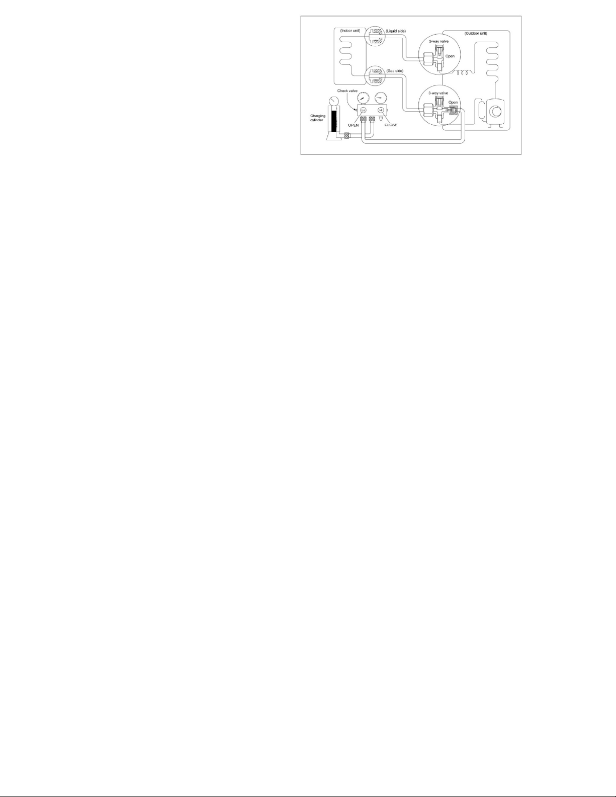
4.4 First-Time Installation
Air and moisture in the refrigerant system cause
the following problems:
●Increases in system pressure
●Increases in operating current
●Decreases in cooling and heating efficiency
●Blocks in capillary tubing caused by moisture
in the refrigerant circuit freezing
●Corrosion of parts in the refrigerant system
caused by water
The indoor units and the pipes between
indoor and outdoor units must be tested for
leakages and evacuated to remove gas and
moisture from the system.
Gas leak check with soap water:
Apply soap water or a liquid neutral
detergent on the connections with a soft brush to
check for leakage in the pipe connecting points. If
bubbles emerge, the pipes are leaking.
1. Air Purging Using the Vacuum Pump
12
1. Completely tighten the flare nuts on the
indoor and outdoor units. Confirm that both
the2-way and 3-way valves are set to the
closed position.
2. Connect the charge hose with the push pin of
the Handle Lo to the 3-way valve gas service
port.
3. Connect the charge hose of the Handle Hi to
the vacuum pump.
4. Fully open the Handle Lo of the manifold
valve.
5. Turn on the vacuum pump to begin
evacuation.
6. Conduct a 30-minute evacuation. Check
whether the compound meter indicates -
0.1Mpa(14.5Psi). If the meter does not
indicate -0.1Mpa(14.5Psi) after 30 minutes
has elapsed, continue evacuation for 20 more
minutes. If the pressure does not reach -
0.1Mpa(14.5Psi) after 50 minutes has
elapsed, check if there are any leaks.
Fully close the Handle Lo valve of the manifold
valve and turn off the vacuum pump. After 5
minutes, confirm that the gauge needle is not
moving.
7. Turn the flare nut on the 3-way valve45°
counterclockwise for 6-7 seconds. Once gas
begins to come out, tighten the flare nut.
Make sure the pressure display on the
pressure indicator is higher than atmospheric
pressure. Then remove the charge hose from
the 3-way valve.
8. Fully open the 2-wayand 3-way valves and
securely tighten the cap on the 3-way valve.
2. Adding refrigerant if the pipe length
exceeds chargeless pipe length
Procedure:
1) Connect the charge hose to the charging cylinder
and open the 2-way and 3-way valves.
With the charge hose you disconnected from the
vacuum pump, connect it to the valve at the
bottom of the cylinder.
If the refrigerant is R410A, place the cylinder
bottom-up to ensure liquid charging is possible.
2). Purge the air from the charge hose.
Open the valve at the bottom of the cylinder and
press the check valve on the charge set (be
careful of the liquid refrigerant).
3) Place the charging cylinder onto the electronic
scale and record the weight.
4) Turn on the air conditioner in cooling mode.
5) Open the valves (Low side) on the charge set.
Charge the system with liquid refrigerant.
6).When the electronic scale displays the proper
weight (refer to the table), disconnect the charge
hose from the 3-way valve’s service port
immediately and turn off the air conditioner before
disconnecting the hose.
7). Mount the valve stem caps and the service port
Use a torque wrench to tighten the service port
cap to a torque of 18N.m(13.27 ft·lbs).
Be sure to check for gas leaks.

13
4.5 Adding Refrigerant after Long-Term
System Operation
Procedure
1) Connect the charge hose to the 3-way service
port and open the 2-way and 3-way valve.
Connect the charge hose to the valve at the
bottom of the cylinder. If the refrigerant is R410A,
place the cylinder bottom-up to ensure liquid
charge.
2). Purge the air from the charge hose.
Open the valve at the bottom of the cylinder and
press the check valve on the charge set to purge
the air (be careful of the liquid refrigerant).
3) Place the charging cylinder onto the electronic
scale and record the weight.
4) Turn on the air conditioner in cooling mode.
5) Open the valves (Low side)on the charge set and
charge the system with liquid refrigerant.
6).When the electronic scale displays the proper
weight (refer to the gauge and the pressure of the
low side), disconnect the charge hose from the 3-
way valve’s service port immediately and turn off
the air conditioner before disconnecting the hose.
7). Mount the valve stem caps and the service port.
Use torque wrench to tighten the service port cap
to a torque of 18N.m(13.27 ft·lbs).
Be sure to check for gas leaks.
4.6 Procedure when servicing the indoor
unit refrigeration circuit.
1. Collecting the refrigerant into the outdoor
unit
Procedure
1). Confirm that both the 2-way and 3-way valves
are set to the opened position
Remove the valve stem caps and confirm that the
valve stems are in the opened position.
Be sure to use a hexagonal wrench to operate the
valve stems.
2). Connect the charge hose with the push pin of
handle lo to the 3-way valves gas service port.
3).Air purging of the charge hose.
Open the handle Lo valve of the manifold valve
slightly to purge air from the charge hose for 5
seconds and then close it quickly.
4). Set t e 2-way valve to the close position.
5). Operate the air conditioner at the cooling cycle
and stop it when the gauge indicates 0.1MPa.
6). Set the 3-way valve to the closed position
immediately
Do this quickly so that the gauge ends up indicating
0.3 to 0.5Mpa.
Disconnect the charge set, and tighten the 2-way
and 3-way valve’s stem nuts.
Use a torque wrench to tighten the 3-way valves
service port cap to a torque of 18N.m.
Be sure to check for gas leakage.
2.Air purging with vacuum pump

14
1) Completely tighten the flare nuts of the indoor
and outdoor units, confirm that both the 2-way
and 3-way valves are set to the closed
position.
2) Connect the charge hose with the push pin of
handle lo to the 3-way valves gas service
port.
3) Connect the charge hose of handle hi
connection to the vacuum pump.
4) Fully open the handle Lo of the manifold
valve.
5) Operate the vacuum pump to evacuate.
6) Make evacuation for 30 minutes and check
whether the compound meter indicates -
0.1Mpa. If the meter does not indicate -
0.1Mpa after pumping 30 minutes, it should
be pumped 20 minutes more. If the pressure
can’t achieve -0.1Mpa after pumping 50
minutes, please check if there are some
leakage points.
Fully close the handle Lo valve of the manifold
valve and stop the operation of the vacuum
pump. Confirm that the gauge needle does not
move (approximately 5 minutes after turning off
the vacuum pump).
7) Turn the flare nut of the 3-way valves about
45° counterclockwise for 6 or 7seconds after
the gas
coming out, then tighten the flare nut again. Make
sure the pressure display in the pressure
indicator is a little higher than the atmosphere
pressure. Then remove the charge hose from the
3 way valve.
8) Fully open the 2 way valve and 3 way valve
and securely tighten the cap of the 3 way
valve.
4.7 Evacuation after servicing the outdoor
unit refrigeration circuit
1. Evacuation of the complete refrigeration
circuit, Indoor and outdoor unit.
Procedure:
1). Confirm that both the 2-way and 3-way valves
are set to the opened position.
2). Connect the vacuum pump to 3-way valve’s
service port.
3). Evacuation for approximately one hour.
Confirm that the compound meter indicates -
0.1Mpa (500 Microns / 29.9 in,hg).
4). Close the valve (Low side) on the charge set,
turn off the vacuum pump, and confirm that the
gauge needle does not move (approximately 5
minutes after turning off the vacuum pump).
5). Disconnect the charge hose from the vacuum
pump.
2. Refrigerant charging
Procedure:
1). Connect the charge hose to the charging
cylinder, open the 2-way valve and the 3-way
valve.

15
Connect the charge hose which you disconnected
from the vacuum pump to the valve at the bottom
of the cylinder. If the refrigerant isR410A, make
the cylinder bottom up toensure liquid charge.
2). Purge the airfrom the charge hose
Open the valve at the bottom ofthe cylinder and
press the check valve on the charge setto purge
the air (be careful ofthe liquid refrigerant).
3) Put the charging cylinder ontothe electronic
scale and record the weight.
4).Open the valves (Low side) on the charge set
and charge the system with liquid refrigerant
If the system cannot be charge with the specified
amount ofrefrigerant, orcanbe charged with a
little at atime (approximately 150g each time) ,
operating the air conditioner in the cooling cycle;
however, one time isnot sufficient, wait
approximately 1 minute and then repeat the
procedure.
5).When the electronic scale displays the proper
weight, disconnect the charge hose from the 3-
way valve’sservice portimmediately
If the system has been charged with liquid
refrigerant while operating the air conditioner, turn
off the air conditioner before disconnecting the
hose.
6). Mounted the valve stem caps and the service
port. Use torque wrench to tighten the service
port cap to a torque of18N·m (13.27 ft·lbs).
Always leak check after servicing the refrigerant
system.
For MMCUT27AS3 / MMCUT36AS4 /
MMCUT48AS5
There are one low-pressure centralized valve and
one high-pressure centralized valve, it will be
more time saving when vacuum and recycle
refrigerant. But refer to the previous instruction
when vacuum and recycle refrigerant.

16
5. Electronic Function
5.1 Abbreviation
T1: Indoor ambient temperature
T2: Middle indoor heat exchanger coil
temperature
T2B: Indoor heat exchanger exhaust coil
temperature (located on the outdoor unit)
T3: Outdoor heat exchanger pipe temperature
T4: Outdoor ambient temperature
T5: Compressor discharge temperature
5.2 Electric Control Working Environment.
5.2.1 Input voltage: 230V.
5.2.2 Input power frequency: 60Hz.
5.2.3 Indoor fan standard working amp.: <1A
5.2.4 Outdoor fan standard working amp.: <1.5A.
5.2.5 Four-way valve standard amp.: <1A.
5.3 Main Protection
5.3.1 Compressor Restart Delay
---- The compressor takes 1 minute to start up the
first time. Further restarts take 3 minutes.
5.3.2 Temperature Protection of Compressor
Discharge.
When the discharge temperature of the
compressor rises, the running frequency is limited
according to the following rules:
----If 105℃(221 ℉)≦T5<110℃(230 ℉),
maintain the current frequency.
----If the temperature increase and T5≧110℃
(230 ℉), decrease the frequency to a lower level
every 2 minutes till to F1.
---If T5≧115℃(239 ℉) for 10 seconds, the
compressor stops and then restart untill T5<90℃
(194 ℉).
5.3.3 Fan Speed Malfunction
---- If outdoor fan speed is lower than 100RPM or
higher than 2400RPM for 60 seconds or more,
the unit stops and LED displays E8 failure code.
5.3.4 Inverter Module Protection.
---- The inverter protection module ensures that
faults related to current, voltage, or temperature
does not damage the inverter.
If these protections are triggered, the A/C unit
stops and the LED displays the failure code.
The unit restarts 3 minutes after the protection
mechanism has turned off.
5.3.5 Low Voltage Protection
VOLTAGE
No limit
VOLT_LTM_FREQ1_ADD
VOLT_LTM_FREQ2_ADD
Note: If low voltage protection triggers and
voltage is not restored to normal within 3
minutes, the protection remains active even
after a machine restart.
5.3.6 Compressor Current Limit Protection
The temperature interval for the current limit is
the same as the range of the T4 frequency limit.
Cooling mode:

17
CoolReturnI
The difference between current limit
and shutdown current
CoolT4Zone5I
Cooling T4
≥
50
℃
current limit value
CoolT4Zone4I
Cooling 49
>
T4
≥
45
℃
current limit
value
CoolT4Zone3I
Cooling 44
>
T4
≥
41
℃
current limit
value
CoolT4Zone2I
Cooling 40
﹥
T4
≥
33
℃
current limit
value
CoolT4Zone1I
Cooling 32
>
T4
℃
current limit value
CoolStopI
Cooling stop protection current value
Heating mode:
℃
15
14 HeatT4Zone4I
10
9 HeatT4Zone3I
6
5 HeatT4Zone2I
HeatT4Zone1I
HeatReturnI
The difference between current limit
and shutdown current
HeatT4Zone4I
Heating
T4
≥
15
℃current limit
value
HeatT4Zone3I
Heating
14
>
T4
≥
10
℃current
limit value
HeatT4Zone2I
Heating
9
>
T4
≥
6
℃current limit
value
HeatT4Zone1I
Heating 5
>
T4 current limit value
HeatStopI
Heating stop protection current
value
5.3.7 Indoor / Outdoor Units Communication
Protection
If the indoor units do not receive the feedback
signal from the outdoor units for 2 consecutive
minutes, the unit stops. The unit displays the
failure code.
5.3.8 High Condenser Coil Temp. Protection
5.3.9 Outdoor Unit Anti-Freezing Protection
When T2<4℃for 250seconds or T2<0℃, the
indoor unit capacity demand is zero and resumes
normal operation when T2>8℃and the protection
time is no less than 3 minutes.
5.3.10 Oil Return
Rules for Operation
1. If the compressor frequency continues to be
lower than the frequency set for setting time, the
unit raises the frequency to the frequency set for
setting time and then resumes with the former
frequency.
2. The EXV continues at 300p while indoor units
maintain their operation.
T3
Resume
Off
Decrease
Hold
℃CoolT4Zone5I
50
49
45 CoolT4Zone4I
44
41
40 CoolT4Zone3I
33
32
CoolT4Zone2I

18
If the outdoor ambient temperature is higher than
the set frequency during oil return, the unit stops
the oil return process.
5.3.11 Low Outdoor Ambient Temperature
Protection
When the compressor is off and T4 is lower than -
35℃for 10 seconds, the unit stops and displays
“LP.”
When the compressor is on and T4 remains lower
than -40℃for 10 seconds, the unit stops and
displays “LP.”
When T4 is no lower than -32℃for 10 seconds,
the unit exits protection.
5.4 Control and Functions
5.4.1 Capacity Request Calculation
Cooling Mode:
T1 Ts
3
1
1e
c
a4
2
0
2
3
01
f
d
b
Capacity area a b c d e f
Norm code (N)
3
2
1.5
1
0.5
0
Model
9K
12K
18K
24K
HP
1.0
1.2
1.5
2.5
Note: The final result is an integer.
Use the following table and final capacity
request to confirm the operating frequency.
Frequency (Hz) 0
COO
L_F1 COO
L_F2 …
…COOL
_F24
COO
L_F2
5
Amendatory
capacity
demand.
0
1 2 …
…24 25
The maximum running frequency is adjusted
according to the outdoor ambient temperature
℃
55
54
Fmax=
T4FREMAXC0
51.5
50.5
Fmax= T4FREMAXC1
45.5
44.5
Fmax= T4FREMAXC2
39
38
Fmax= T4FREMAXC3
33
32
Fmax= T4FREMAXC4
30
29
Fmax= T4FREMAXC5
22
20
Fmax= T4FREMAXC6
10
8
Fmax= T4FREMAXC7
0
-2
Fmax= T4FREMAXC8
-10
-12
Fmax= T4FREMAXC9
Fmax= T4FREMAXC10
Heating Mode
T1 Ts
4
0
a
3
1
-1
3
12
0
b
c
d
e
f
2
Capacity area a b c d e f
Norm code (N) 3 2 1.5 1 0.5 0
Model
9K
12K
18K
24K
HP
1.0
1.2
1.5
2.5
Note: The final result is an integer.
Then modify it according to a T2 average
(correction):

19
Note:Average value of T2:Sum T2 value of all
indoor units)/ (indoor units number
℃
T2 average
Decrease frequency
47
Keep frequency
40
Increase frequency
Use the following table and final capacity
request to confirm the operating frequency.
Frequency
(Hz) 0 HEAT
_F1 HEAT
_F2 … HEAT
_F24 HEAT
_F25
Amendatory
capacity
demand.
0 1 2 … 24 25
The maximum running frequency is adjusted
according to the outdoor ambient temperature
℃
34
33
Standby
28
27 Fmax=T4FREHEATMAX1
25
24 Fmax=T4FREHEATMAX2
22
21 Fmax=T4FREHEATMAX3
19
18 Fmax=T4FREHEATMAX4
17
16 Fmax=T4FREHEATMAX5
15
14 Fmax=T4FREHEATMAX6
12
11 Fmax=T4FREHEATMAX7
6
5 Fmax=T4FREHEATMAX8
1
0 Fmax=T4FREHEATMAX9
-3
-4 Fmax=F21
-7
-8 Fmax=F22
-11
-12 Fmax=F23
-15
-16 Fmax=F24
Fmax=F25
5.4.2 Defrosting Control
Conditions for Defrosting:
After the compressor starts and enters normal
operation, mark the minimum value of T3 from
the 10th to 15th minute as T30.
If any one of the following conditions is satisfied,
the unit enters defrosting mode:
1) If the compressor’s cumulative running time
reaches 29 minutes and T3< TCDI1 and T3+
T30SUBT3ONE≦T30.
2) If the compressor cumulative running time
reaches 35 minutes and T3< TCDI2 and T3+
T30SUBT3TWO≦T30.
3) If the compressor cumulative running time
reaches 40 minutes and T3< -24C for 3 minutes.
20
4) If the compressor cumulative running time
reaches 120 minutes and T3<-15℃.
Defrost Stop Conditions
If any one of the following conditions is satisfied,
defrosting ends and the unit returns to normal
heating mode:
----T3 rises above than TCDE1℃.
----T3 remains at TCDE2℃or above for 80
seconds.
----The machine runs for 10 consecutive minutes
in defrosting mode.
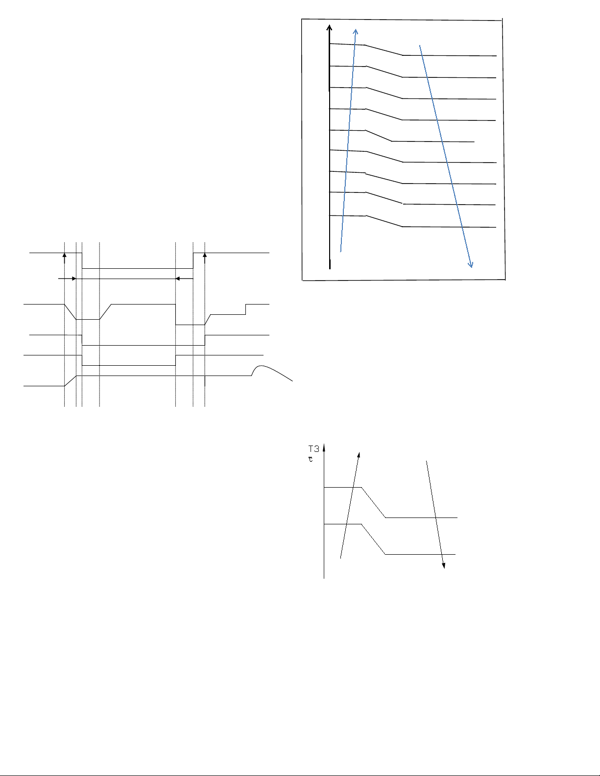
Defrosting Action
:
off
on
Cool-F9
10S
30S
TimeA
10S
4-way valve
defrosting
Defrosting over
compressor
Indoor fan
Outdoor fan
EXV open
frequency
Max 10 minutes
frequency
Compressor stops
off
Anti-cold control
off
480P
480P for 240s
Condition of ending defrosting:
If any one of following items is satisfied,
defrosting will stop and the machine will turn to
normal heating mode.
①T3 > TempQuitDefrost_ADD ℃;.
②The defrosting time achieves 10min.
③Turn to other modes or off.
5.4.3 Outdoor Fan Control
5.4.3.1 Cooling Mode
Under normal operating conditions, the system
chooses the running fan speed according to the
ambient temperature:
Outdoor
℃
45
43
Supper high fan speed
28
26 High fan speed
25
23
Middle fan speed
22
20
Low fan speed
19
17
Supper low fan speed
10
9
Breeze fan speed
0
-1 F fan speed
-5
-6
G fan speed
-10
-11
H fan speed
I fan speed
When low ambient cooling is in effect::
Outdoor fan speed control logic (low ambient
cooling)
When T4 <15 ℃(59 ℉) and T3 < 30 ℃(86 ℉),
the unit enters into low ambient cooling mode.
The outdoor fan chooses a speed according to T3.
When T3≥38 ℃(100.4 ℉) or when T4≥20 ℃
(68 ℉), the outdoor fan chooses a speed
according to T4 again.
38
Exit low ambient cooling
mode
,
run with high fan
for 1 minute
Low
30
27
23
off
This manual suits for next models
3
Table of contents
Popular Heat Pump manuals by other brands


Walter Roller
Walter Roller Silent Line WPV Mounting instructions

EMI
EMI AmericaSeries S1H9A Specifications and Performance

Heat Controller
Heat Controller RPHE-093G Series Installation & operation manual

Econar
Econar GeoSource DualTEK GV Series Installation and operating instructions

Airwell
Airwell XLM9 Installation and maintenance manual

Bryant
Bryant 548J Product data