TEC Prizrak-810 BT Parts list manual

UNLIMITED AUTOM BILE CONTROL
TECHNICAL
DESCRIPTION
GSM-CAR ALARM
PRIZRAK — PROTECTION AGAINST PROFESSIONAL CARJACKING
www.tecel.ru/en/

2
TEC-67231-2 Technical description Prizrak-8xx BT
Table of contents
Alarm description.....................................................................................2
Preliminary introduction.......................................................................3
Prizrak 8xx/BT series new features...................................................3
Terminology.........................................................................................3
Optional equipment.............................................................................3
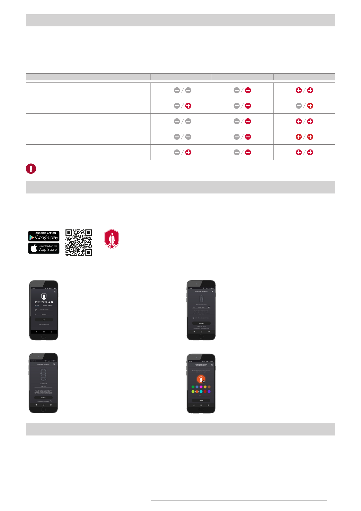
Upgrading the alarm with optional radio tags......................................4
Table1. «Upgrading the alarm with radio tags»....................................4
Mobile application «Prizrak»..............................................................4
Telematic sercvice «Prizrak monitoring»...............................................4
Controlling via SMS...............................................................................5
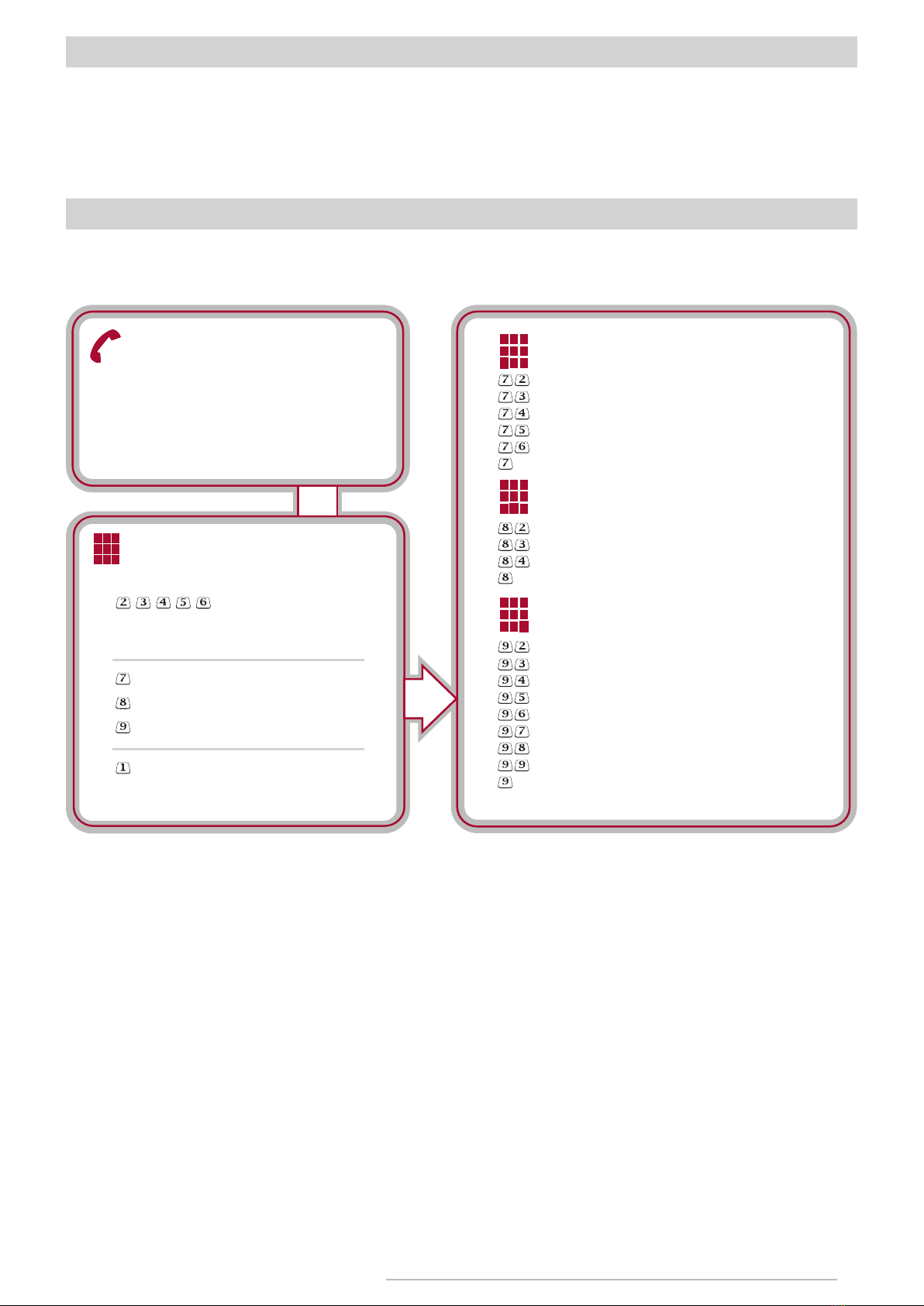
Controlling via phone call......................................................................5
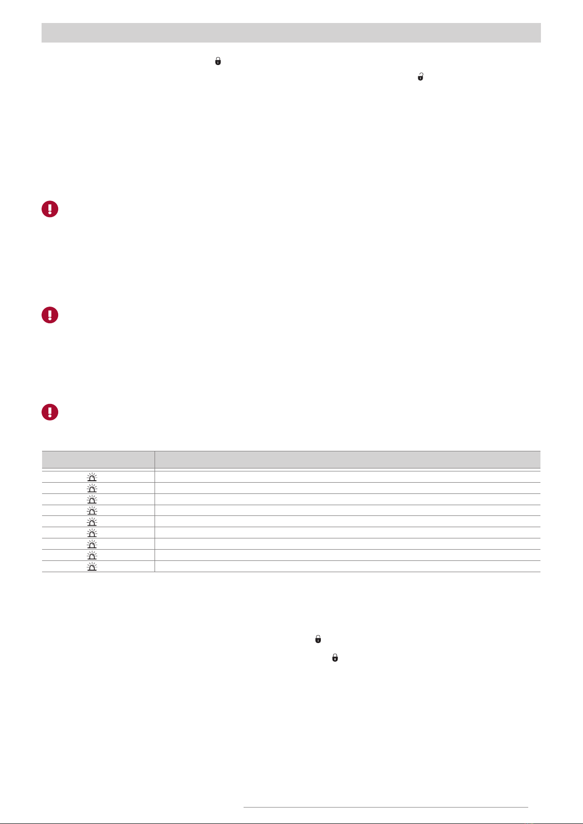
System operating algorythms................................................................6
Table2. Alarm trigger memory............................................................6
Vehicle’s CDL unlocking blockage if a tag
is not in range .......................................................................................7
Remote starting the engine and controlling the engine heater............7
Immobilizer...........................................................................................8
AntiHiJack...........................................................................................8
Immobilizing a vehicle by imitating
the engine Start/Stop button push.....................................................8
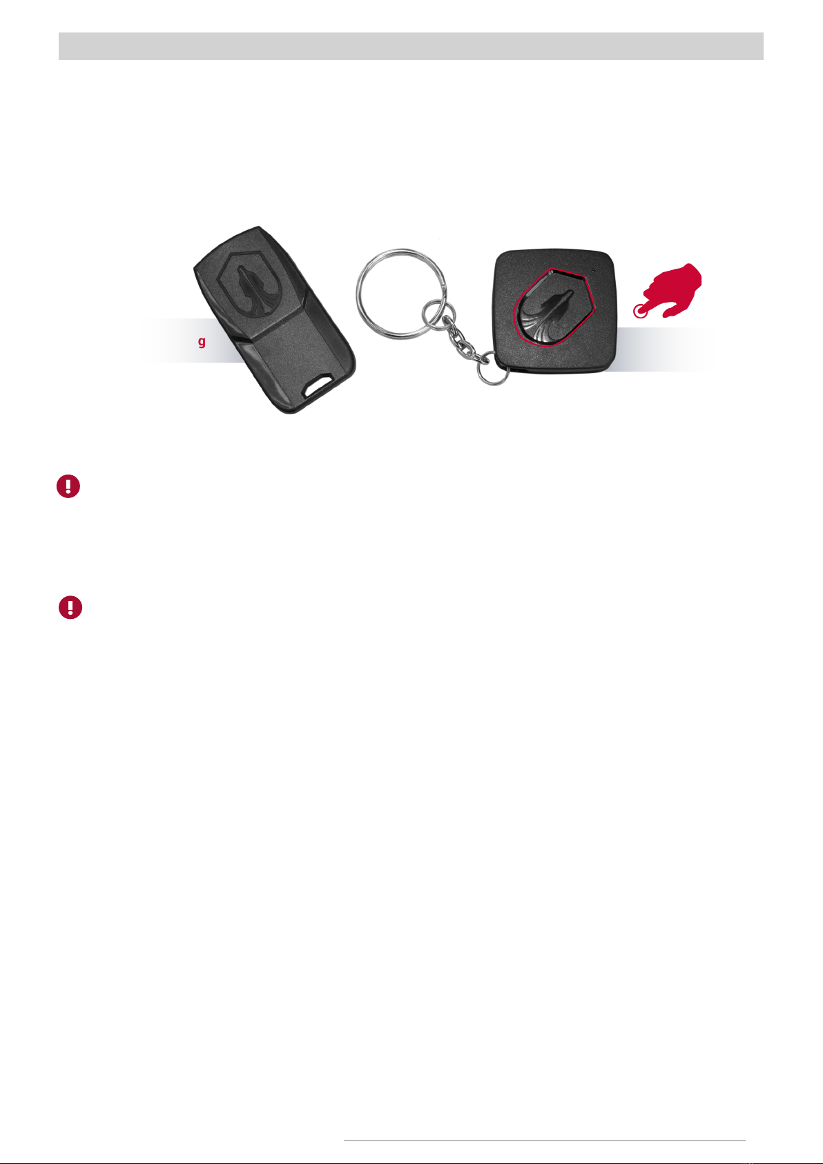
Radio tag (Key ID tag and Slim tag)...................................................10
Authentication methods...................................................................11
Table 3. Authentication methods.......................................................11
Table 4. Warning beeps following after authentication ...................11
Maximum protection in dangerous places..........................................12
Disarming AntiHiJack with a tag.....................................................12
PIN code............................................................................................12
PUK code.............................................................................................12
Service/valet mode...........................................................................13
Optional features..............................................................................13
Installing the alarm system...............................................................14
Wire harness.....................................................................................15
Table5.Wireharnessdescription......................................................15
Relay pLine-221 description and installation recommendations..16
Table 6. Relay’s wire harness description.........................................16
Implementing the remote engine start feature................................17
Configuring thealarm.........................................................................18
1st step. Interfacing the alarm with a vehicle..................................18
2nd step. Configuring the alarm features........................................19
Table 7. Codes for programming menus...........................................19
Configuring hardware features........................................................19
Menu 1. Hardware functions configuration....................................19
Menu 1.2. Programmable inputs/outputs configuration..................21
Table 8. Programmable outputs features..........................................22
Table 9. Programmable inputs features.............................................24
Adjusting the feature «Vehicle’s CDL unlocking
blockage until the radio tag is detected»...........................................26
Adjusting the «Beach mode» feature.................................................27
Adjusting the built-in sensors............................................................28
Table 10. Built-in sensors...................................................................28
Configuring the engine heater settings..............................................28
Table 11. Engine heater settings........................................................28
Configuring the remote start mode ...................................................29
Table12. Remote start mode settings................................................29
Table 13. Built-in keyless immobilizer bypass
module parameters adjustment.........................................................30
Adjusting the analog SLAVE feature..................................................31
Diagnostic trouble codes reading feature settings..........................31
Table 14. Diagnostic trouble codes reading feature settings..........32
Configuring the hood compartment module HCU-230/BT..............33
Table 15. Hood compartment unit HCU-230/BT adjustment..........32
Registering the hood compartment module HCU-230/BT module.33
Cancelling registration of the HCU-230/BT module........................34
Customizing the user features...........................................................34
Menu 2. User functions settings........................................................34
Registering new radio tags.................................................................35
Testing detection quaility of a radio tag............................................35
Changing a PIN code..........................................................................35
Changing the programming button ..................................................36
Customizing the operating mode for SIM cards (Menu 24).............36
Table 16 SIM card settings (menu 24)...............................................36
Programming examples.....................................................................37
Resetting to default values................................................................37
Controlling the alarm via SMS commands........................................38
Table 17. SMS commands to control the GSM car alarm Prizrak....38
Programming studio.........................................................................38
GSM-alarm Prizrak 8xx/BT connection diagram.............................39
Standard notification settings...........................................................40
Alarm elements installation scheme in a vehicle.............................41
Standard alarm set.............................................................................42
Product specifications and operating conditions.............................42
Alarm description

3
TEC-67231-2 Technical description Prizrak-8xx BT
Alarm description
Preliminary introduction
The alarm was designed for the following purposes:
• For protecting a vehicle from theft while it is parked and from hijacking while it is being operated on the road.
• For notifying the vehicle’s owner that the alarm has been triggered while in parking.
• For providing the vehicle users with the possibility of remotely starting and shutting down the engine to warm up or cool down the interior
(optional feature, may require ESM-250 remote start module).
• For locating the vehicle and for viewing vehicle’s tracks and travel history on the map (an optional GPS/GLONASS-270 module is required).
The alarm comes with the integrated GSM modem which provides full control over the vehicle and the alarm itself via the special mobile
application Prizrak (available at the App Store and Google play), telematic web service «Prizrak Monitoring», phone call, SMS messages. Vehicle
owner’s authentication is verified by carrying the Key-ID tag, Slim-tag, Smartphone tag (Bluetooth Smart technology) in the vehicle’s range and/
or by entering PIN code with vehicle’s original buttons. The alarm is equipped with the embedded tilt/displacement and shock sensors and it may
be upgraded with optional external sensors. 2CAN technology makes it possible for the alarm to simultaneously operate with two CAN-buses
at the same time, improving the alarm functionality for some vehicles. Web-application-Integrator (https://int.tecel.ru/) contains information
on the alarm compatibility with specific vehicles, and the list of vehicles compatible with the alarm as well as the information on peculiarities of
vehicle functionality.
Main advantages of the alarm:
• the alarm may be controlled with vehicle’s standard remote key, KeyID-tag, mobile phone and with standard vehicle’s buttons;
• remote and automatic engine start;
• there is no need to hide a spare key inside the vehicle to remote start it (not available fore all cars, see Integrator to check the feature
availability for a specific vehicle).
Prizrak 8xx/BT series new features:
• Short range radio channel based on Bluetooth 4.2;
• Habitual radio tags — Key tag «Key-ID» and Slim-tag support Bluetooth Smart (2.4 GHz radio channel based on Bluetooth 4.2);
• Settings of the main alarm unit can be adjusted via Bluetooth (special TEC-prog USB-Bluetooth adapter required);
• Any 8xx/BT series car alarm can be upgraded with radio tags;
• The default settings for the authentication method in Prizrak-810 and Prizrak-820 have been changed. Once radio tags have been
registered into the alarm, they can be used for authentication without having to perform additional adjustments;
• The HCU-230 hood compartment module is now controlled via Bluetooth (there is no need to route wires into the engine compartment
anymore);
• Integrated diagnostic system based on OBD II protocol (diagnostic can be carried out via the smartphone app);
• Intelligent system for erasing diagnostic trouble codes that appear after triggering the engine blocking, after remote starting the vehicle’s
engine or engine heater;
• Dual SIM card compatibility (only for 4G systems);
• Supports the broadband cellular network technology of the fourth generation — 4G (only the systems with 4G GSM modem).
Terminology
GSM code: the code is used in oder to get a vehicle registered in the mobile app «Prizrak», telematic Web service «Prizrak monitoring» and
for controlling the alarm via phone calls or SMS.
User’s personal GSM code is located on the plastic card under the protective film. GSM code may be changed by the alarm user during day-by-
day exploitation (via the mobile app or a phone call). The temporary GSM code «1111» was designed for installation and adjustment convenience.
It is valid before a vehicle has travelled 10 km after the alarm installation. Thereupon, the system will request to enter an unique user’s GSM code.
Programming button. The programming button is used for entering the PUK code, for adjusting various alarm features and etc. It is allowed
to use as the programming button:
• the embedded Key-ID button.
• one of the vehicle’s factory buttons. In most vehicles the button is assigned automatically, but it may also be programmed by an installer.
Radio tag (Key-tag «Key-ID» and/or Slim tag): an electronic key that must be always carried around when operating a vehicle. Key-ID tag is
destined for comfortable use in combination with OEM smart key and is securely protected against intellectual hacking. Slim tag has miniature
dimensions and is designed to be kept together with vehicle’s documents.
Authentication. Authentication is a procedure for verifying wheather a vehicle owner is authorized to drive the vehicle or not, to be more
specific it is a radio tag and/or PIN code identification. Radio tag and PIN code are two independent authentication contours, to disable each
contour — two different authentication procedures should be carried out. CDL — central door locking system.
Optional equipment
The use of an optional equipment provides new possibilities and allows to enhance security and comfort level during the vehicle exploitation.
Hood compartment unit HCU-230 — was designed for controlling the aftermarket electromechanical hood locks via an encoded communication
channel.
CAN-relay Implant 1A (2x3) — wireless engine locking relay. Data exchange between the main alarm unit and CAN-relay Implant is carried
out over CAN interface — reliable connection is guaranteed even at the strongest interferences in airwaves.
Autoscanner CheckControl: the CAN relay immobilizes a vehicle either via a special CAN bus command or by cutting a low-current electrical
circuit; by shunting the vehicle’s sensors.
GPS/Glonass-270 module — provides accurate vehicle location. If this module is not connected to the main alarm module - the current vehicle
location is determined via LBS (Location-based Servises). The vehicle location is determined based on the signals of the closest cell-phone
towers. The alarm detects a signal from the nearest cell-phone tower and displays the vehicle location near that tower (this doesn’t provide an
accurate location).
Key-ID tag (Bluetooth Smart) — equipped with the embedded button which can be used to lock/unlock the vehicle’s central door locking
system and the vehicle owner authentication. The embedded button can also be used as the programming button, assuming that this feature
was properly set up.
Slim tag (Bluetooth 4.2) — is used for vehicle owner authentication. It is possible to purchase optional radio tags for Prizrak-810/BT or
Prizrak 820/BT.
Hood compartment unit HCU-230/BT (Bluetooth) — was designed for controlling the aftermarket electro-mechanical hood locks and the
other equipment located in the engine compartment. Bluetooth technology allows to avoid running the alarm wires from the cabin into the engine
compartment.

4
TEC-67231-2 Technical description Prizrak-8xx BT
Upgrading the alarm with optional radio tags
Any alarm modification from the 8xx/BT series can be equipped with optional radio tags. It is possible to program up to 8 radio tags into
one alarm unit. A radio tag can be used for authentication right after it has been registered into Prizrak-810/BT or Prizrak-820/BT, no additional
adjustments required.
Prizrak-800 Style doesn’t support a vehicle owner authentication with radio tags, though the alarm functionality can be improved by equipping
it with optional tags. The Table №2 shows the alarm functionality before and after equipping it with optional radio tags.
Table 1. The alarm functionality comparison table before and after adding optional tags
Alarm features Prizrak-800 Style Prizrak-810/820 Prizrak-830/840
Authentication with radio tag
Vehicle locking/unlocking with Key-ID tag
Radio tag serch for «Disarming confirmation after
unlocking the vehicle with OEM remote»
CDL unlocking blockage when radio tag is not in range
«Free hands» during remote start mode operaton
One radio tag can’t be registered into several alarm modules at the same time.
Mobile application «Prizrak»
The mobile application «Prizrak» — is a software designed and developed for managing the vehicle security system «Prizrak». The software
allows registered users to obtain all important information about the vehicle state from the screen of a smartphone and provides convenient
control over the alarm features from virtually anywhere: remote starting the engine, arming/disarming, locking/unlocking, adjusting the shock
and tilt/displacement sensors, locating the vehicle and etc.
The mobile app «Prizrak» is available for download in the App Store and Google Play.
Free mobile application
In case if your smarthone is not equipped with QR code scanner — type in the search bar (Google
Play or App Store) application name — Prizrak.
Getting your vehicle registered into the mobile app «Prizrak»
Telematic service «Prizrak monitoring»
The telematic web service «Prizrak monitoring» allows analyzing vehicle’s trips and events occured duaring a selected period of time: view
the vehicle’s tracks, fuel consumption, various events.
Log into an exisiting account of the Prizrak
system or web service Prizrak monitoring.
You can create a new account if you don’t
have one yet using your cellphone number or
an e-mail.
Scratch off the protective slip on the plastic card
supplied with the Prizrak system to reveal the
secret GSM code, enter the four-digit code in the
app to register your vehicle.
Type in the number located under the bar
code of the plastic card supplied with the
Prizrak device or scan the bar code using your
smartphone’s camera. Tap the link «I don’t
have a card» if you don’t have one and follow
further the instructions.
Give your vehicle a name (any name).
You may select a color for the app interface
and upload a photo.
Press the button «Continue» to complete
vehicle registration.
1. Authorization
3. Confirmation
2. Users’ access
4. Completing the registration

5
TEC-67231-2 Technical description Prizrak-8xx BT
Control via SMS
It is possible to control your alarm via text messages of the following format:
Access code*Command№#Parameter.
Access code – a code to access the system.
Command№ – a command code of the voice menu.
Parameter – it is used in addition to some commands when necessery.
For example: 1111*822# (this is the command to disarm the alarm; in this example the access code is the factory code «1111»).
Control via phone call
The alarm functions can be managed via phone call. Ability to control the alarm via the voice menu may be very helpful in case if the system
temporarily loses the internet connection and it is not possible to use the mobile app as well as if you don’t use smartphones at all.
Smart voice menu structure
Was designed for quickly obtaining the
most important information about the
alarm and vehicle state.
Quick access information
Quick Access Commands
System Information
Control Commands
Customization
Help
Control Commands
Customization
System Information
Vehicle status information
Alarm trigger memory
Events log
List of disabled systems and features
Task manager contents
Help
Task manager
Automatic startups and auxiliary channels
Sensors
Quick access information
Quick access commands
System users and access rights
Notification settings
Advanced settings
Help
Alarm control commands
Startups and auxiliary channels
SIM-card balance request and etc.
Help
Basic system information.
7
8
9
These commands can be customized.
789
456
123

6
TEC-67231-2 Technical description Prizrak-8xx BT
Alarm system operating algorithms
Arming/Disarming
To arm the alarm press the OEM remote lock button or lock the doors with keyless entry system, or twist the car key in the driver’s door
lock cylinder into locked position. The alarm will warn you of its arming by one siren chirp and LED will flash. After a while the LED flashes will
become less frequent in order to save car’s battery energy. To disarm the alarm press OEM remote unlock button, or unlock the vehicle with
keyless entry system. The alarm will emit 2 siren chirps, LED will fade. It is also possible to arm/disarm the alarm with the Key-ID tag button.
Automatic rearming
The alarm will automatically rearm 1 minute after disarming via phone or Key-ID tag if all doors, hood and trunk remained closed. If a
vehicle has been disarmed with OEM remote key then the «automatic rearming» operates according to the vehicle manufacturer algorithms. The
«automatic rearming» function is very convenient when a vehicle has been disarmed unintentionally. The function is disabled by default (see
Menu 2. «User functions configuration»).
Open compartment warning
If you have left a door, hood or trunk opened and armed the alarm, it will warn you with 3 siren chirps. LED will inform you of what exactly you
have forgotten to close by a certain number of flashes:
• Two flashes – the hood is opened.
• Three flashes – the trunk is opened.
• Four flashes – the door (doors) opened.
The alarm can not monitor penetration into a car through an unclosed compartment. It is possible to just close the opened door/s
(hood, trunk) without disarming and re-arming the vehicle, and then the alarm will automatically take that compartment under control.
Alarm triggering
The alarm is equipped with two built-in digital sensors: shock and tilt/displacement sensors. Through these sensors the alarm reacts to such
external impacts as shocks, bumps and vibrations or attempts to tow a car away. An optional sensor may be connected to the alarm if needed
(multiplex or standard one).
While in armed mode the alarm responds to impacts in two ways: warning and alert. Warning is triggered if shock sensor has been slightly
impacted. In this case the siren will chirp several times.
Alert will trigger if any door, hood or trunk has been opened, when the tilt/displacement sensor has been triggered and when the shock sensor
has been hardly impacted.
Meanwhile the alarm will go off and hazard lights will flash during 30 seconds.
The sensors sensitivity can be adjusted in the mobile app or via phone call.
Automatic annoyance override
In case if the alert has been triggered from one of the sensors three times within an hour — the alarm will start ignoring that sensor. The alarm
will start responding to that sensor if only there is no any impact on that sensor within the next hour. This function cancels the alarm panic, but
not the warning signals.
Diagnosing the alarm triggers when disarming
The alarm will send you an SMS message or call you (depending on the chosen setting) to notify you about the reason why the alarm panic
has triggered.
The trigger history is also available in the mobile app «Prizrak», web-service «Prizrak monitoring» and in the intelligent voice menu.
The intelligent voice menu provides more detailed information on the alarm trigger history.
When disarming, there will be 4 siren chirps and LED will start indicating the alarm trigger causes in case if it has been triggered (see Table 2).
Teble 2. Alarm trigger memory
LED flashes Alarm trigger reason
x1 «Automatic annoyance override» feature triggered
x2 Hood opened
x3 Trunk opened
x4 Door (doors) opened
x5 Shock sensor triggered (alert)
x6 Shock sensor triggered (warning)
x7 Tilt/displacement sensor triggered
x8 Additional sensor triggered (alert)
x9 Additional sensor triggered (warning)
Arming with sensors exclusion
There are situations when disabling the siren sound is preferable when alarm is triggered from sensors.
To disable the sensors:
1 Arm the alarm.
2 Not later than in the next 3 seconds press the OEM remote lock button , the siren will emit a long intermittent sound then after a pause
— one chirp — the warning mode is disabled. The alarm will not be reacting to slight impacts on the vehicle.
3 Not later than in the next 3 seconds press the OEM remote unlock button , the siren will emit a long intermittent sound then after a
pause — 2 chirps — all sensors are disabled.
Releasing the trunk without disarming
The trunk lid can be released with the OEM remote or keyless entry system while the alarm is armed. While the trunk is being opened the
alarm quits reacting to the sensors, but will still monitor doors so the vehicle remains secured from intrusion. As soon as the trunk is closed, the
system takes it under control and re-enables all sensors.
«Beach mode» function
The function is convenient in summer time when the car owner is having rest at the beach and is afraid to carry around the car key, radio tag
and smartphone because they may be stolen or lost. A car owner may leave all those belongings inside the car. For vehicle locking/unlocking is
used a secret code which is not set by default and is subject for assigning by an installer. The code is entered with one of the vehicle’s exterior
button such as keyless entry system buttons located on the door handles (if available), trunk lid buttons or with an additionally installed button
(see page 27).
Radio tag search for disarming confirmation
If this feature is enabled the alarm performs the radio tag search each time the car is unlocked with factory remote key or keyless entry system
and it will fully disarm if only the alarm has detected the radio tag.

7
TEC-67231-2 Technical description Prizrak-8xx BT
The radio tag search is performed 30 seconds after arming the alarm. The alarm emits intermittent beeps while the radio tag is being
searched. The alarm will trigger in 10 seconds after opening any door, hood, or trunk if the radio tag is not detected in range of the vehicle.
If the alarm has triggered, turn the vehicle’s ignition ON and complete the authentication procedure in order to switch off the siren and
disarm the alarm system.
Vehicle’s CDL unlocking blockage if radio tag is not in range (protection against Relay Attack)
The function will not allow a would-be-thief to get access into the vehicle using Relay Attack equipment that retranslates the original signals
of vehicle’s factory remote key. This feature will also block access into the vehicle if the original car key has been stolen (If the vehicle is equipped
with aftermarket pin door blockers). The vehicle’s doors will unlock if only the system detects a tag in range of the vehicle.
Remote starting the engine and controlling the engine heater
The alarm provides the possibility of automatic and remote start of a vehicle’s engine or an engine pre-heater.
This feature makes the vehicle expluatation more comfortable-you will always be able to warm up or cool down the vehicle interior beforehand.
Moving off with warm engine decreases the engine wear and extends its service life.
The vehicle can be remote started by sending a command via phone or automatically, depending on settings of automatic engine start.
There are several methods to remote start a vehicle: via the mobile app, via phone call, SMS message, from the vehicle’s original remote.
Depending on the engine temperature, battery voltage settings, pre-selected time and days of the week, the system can start the engine
automatically (e.g. for 15 minutes every 3 hours).
In order to remote start the vehicle or engine pre-heater press the «lock» , button 3 times on the vehicle’s smart key. Time interval between
the button presses shouldn’t exceed 3 seconds. The feature is available in 15 seconds after arming a vehicle with factory smart key. If you made
a mistake — take a 5 second pause and try again.
To shut down the engine or engine pre-heater with vehicle’s smart key repeat the same «3-x lock» procedure.
Getting a vehicle ready for the remote start
1 Park your vehicle in an open area.
2 Adjust the most convenient climate system operating mode for worming up or cooling down the vehicle’s cabin.
3 Set the gear shift lever to P (Parking) if your vehicle equipped with AT (Automatic) transmission and shut down the engine. Enable the
«Remote start ready» mode for vehicles equipped with the manual transmission.
4 Arm the vehicle.
Enabling the remote start ready mode (only for MT vehicles)
1 When the vehicle is completely stationary and the engine is running press and hold the brake pedal.
2 Engage the parking brake.
3 Release the brake pedal.
4 Take the car’s key out of the ignition switch, the engine should keep running.
Skip the step №4 if the vehicle is equipped with the engine start/stop button.
5 Depending on the settings for enabling the Remote start ready mode:
• exit the car and close the driver’s door (all doors as well as hood and trunk should remain closed), the engine will shut down;
• arm the vehicle, the engine will shut down.
The «Remote start ready» mode will be cancelled if after enabling it, any door, hood or trunk is opened. The remote start ready mode should
be re-enabled to be able to remote start the vehicle.
Unlocking/Locking while the vehicle is running via remote start
Some vehicles don’t react to the factory smart key commands while the engine is running. In such cases, to unlock or lock the vehicle’s
doors you may use:
• the integrated button of the Key-ID tag.
• the «Free hands» feature (vehicle automatic unlocking/locking when a radio tag is in range).
• mobile app «Prizrak».
• control via phone call or SMS.
Driving off while the engine is running via remote start
Perform the following actions depending on a vehicle:
Vehicles with the engine start/stop button and automatic transmission (if the remote start wiring is connected to the engine start/stop
button and the brake pedal).
1 Open the driver’s door while the vehicle is running via remote start;
2 Press and hold the brake pedal.
3 Shift the gear lever to «D», «R» or «N». Hazard lights will flash 3 times.
4 Complete an authentication procedure. Wait until the confirmation trill sounds and start driving.
Vehicles with engine start/stop button and automatic transmission (if remote start wiring is connected to high current circuits of the car):
Push the start/stop button required amount of times to switch on the ignition (this doesn’t work on all vehicles).
Vehicles with engine start/stop button and manual transmission:
1 Unlock the vehicle while it is running via remote start.
2 Press and hold the brake pedal (if you release the brake pedal the engine will shut down).
3 Release parking brake. Hazard lights will flash 3 times.
4 Complete authentication procedure. Wait for confirmatory sound and start driving.
If you have released the brake pedal and the engine has shutdown before switching the gear lever/releasing the parking brake, wait until
the remote start ready mode is cancelled (in approximately 5 seconds the hazard lights will flash 3 times), turn on the ignition by pushing
the Start/Stop button, carry out authentication and start driving.
Vehicles with classic ignition switch (the transmission type is not important):
1 Unlock the vehicle when the remote start mode is running:
2 Insert the car’s key into the ignition switch without applying on the brake pedal and twist the key to the «IGN» position.
3 Press the brake pedal. Hazard lights will flash 3 times.
4 Complete authentication procedure. Wait for confirmatory sound and start driving.

8
TEC-67231-2 Technical description Prizrak-8xx BT
Immobilizer
Immobilizer — the anti-theft feature was designed for protecting the vehicle from carjacking while in parking. The immobilizer feature enters
the «Guard» mode if the ignition has been switched off for more than 3 sec. Once the feature has switched to «Guard mode» — it is required to
complete an authentication procedure (see Table 3 «Authentication methods») otherwise the vehicle will be immobilized:
• the vehicle will be immobilized after attempting to drive away without authentication (if «Speed monitoring» function is enabled and is
supported by a particular vehicle. Check this function in the Integrator);
• the vehicle will be immobilised in 5 seconds after the ignition is switched on if the «Speed monitoring» feature has been disabled or is
not supported by a particular vehicle.
AntiHiJack
AntiHiJack is a feature designed for protecting a vehicle from hijacking while it is being operated on the road and while it is parked. AntiHiJack
enters the «Guard» mode in the following situation:
• The ignition has been off for more then 3 sec. (if Immobilizer feature is disabled, if Immobilizer is enabled — the alarm follows the
Immobilizer feature algorithms).
• The driver’s door has been opened.
After switching to Guard mode, AntiHiJack function sequentially passes through several phases, and if it is not deactivated by a radio tag
and/or PIN code-the vehicle will be immobilized. Phases are shifted just only while the ignition is ON. After switching the ignition OFF, the alarm
remembers the last phase of the AntiHiJack and the feature will continue to operate when the ignition is switched back ON. The AntiHiJack may
be deactivated in any phase and at any moment by carrying out an authentication procedure.
The «Guard» mode is divided into the following phases:
• Waiting phase;
• Warning phase;
• Engine locking phase.
Waiting phase. AntiHiJack in this phase follows two different algorithms-depending on possebility of «Speed monitoring».
The AntiHiJack waits until the vehicle covers a set distance starting from the moment of «Guard» mode activation if the «Speed monitoring»
has been implemented and/or supported by a particular vehicle.
If «Speed monitoring» hasn’t been implemented (disabled in the «Hardware configuration» menu) or is not supported by a vehicle, than the
«Waiting phase» is devided into three stages:
• Waiting for the driver’s door to be closed.
• Waiting for a preset amount of brake pedal applications.
• Pause before shifting to «Warning» phase.
Warning phase is devided into two stages.
• Vehicle’s driver warning about necessity to enter PIN code.
• Warning the other drivers on the road of possible dangerous situation by flashing the vehicle’s hazard lights (during 10 seconds) due to
upcoming vehicle immobilization.
• The warning beeps will keep informing the driver about necessity to enter PIN code.
Engine locking phase. the engine locking is triggered, the alarm beeper emits warning beeps and the alarm switches on the hazard lights.
The warning beeps and hazard lights will switch off in 15 sec. AntiHiJack remains in engine locking phase until a PIN code is entered.
If «Engine blocking at a safe speed» is enabled — the engine will only be blocked when the vehicle’s speed drops below 30 km/h or after
it comes to a complete stop, this depends on the settings of the «Engine blocking at a safe speed» feature.
The «Engine blocking at a safe speed» feature reduces the possibility of road accidents when the AntiHiJack is triggered.
After switching the ignition off the alarm disables hazard lights and driver audio warning signals. If Immobilizer function hasn’t switched into
the «Guard» mode (see the Immobilizer feature section) then after switching the ignition ON — hazard lights and driver audio warning signals
will be activated for 15 seconds. Herewith, AntiHiJack allows starting the engine, but prevents vehicle driving according to the same algorithms
as the Immobilizer feature does.
If the Immobilizer feature has switched into the «Guard» mode — then after turning the ignition off, AntiHiJack will stop its operation and the
alarm follows the Immobilizer feature algorithms.
Gas pedal locking (forced stop)
The feature will immobilize the vehicle if AntiHiJack is triggered, considering the settings of the «Engine blocking at a safe speed». To
implement this fiunction it is obligatory that the vehicle supports the «Speed monitoring». At the end of Warning phase, if vehicle speed hasn’t
increased within 5 seconds or brake pedal has been pressed within 3 seconds — the gas pedal lock will be triggered for 2 sec. and then disabled
for 5 seconds. This can be repeated for 5 times. Every time gas pedal lock triggers — time duration for which the gas pedal locking will be released,
reduces for 1 second. After the 5-th time the gas pedal lock will be permanent.
It is a must that for «Gas pedal locking» function operation the «Safe engine locking» function to be enabled.
Immobilizing a vehicle by imitating the engine Start/Stop button push
The feature has been developed for vehicles equipped with the Start/Stop button (Push-to-Start button). This anti-theft feature allows to
shutdown the engine by imitating the Start/Stop button push, making the engine blocking very similar to a usual engine shutdown. To implement
such engine locking the alarm output with the programmed feature № 57 («Immobilizing a vehicle by imitating the engine Start-stop button
push») must be connected to a proper wire of the Start/Stop button. When a pulse signal is applied to that wire — the engine must shutdown.
Operation algorithm:
1 If the Immobilizer feature has triggered:
• For vehicles with A/T — when the gear lever is shifted from «P» or «N» to «D» the signal is generated on the output until the engine shuts
down.
• For vehicles with M/T — when the vehicle starts moving — the signal is generated on the output until the engine shuts down.
2 If AntiHiJack has triggered:
The output will generate the signal after the vehicle comes to a complete stop. If the alarm doesn’t recieve the speed data from the CAN-bus,
the vehicle’s engine will be blocked according to the Immobilizer feature operating algorithms when starting the engine next time.
Settings of the options «Engine locking at a safe speed» and «Ability to start the engine before carrying out authentication» don’t affect
the operating algorithms of the «Immobilizing a vehicle by imitating the engine Start/Stop button push».

9
TEC-67231-2 Technical description Prizrak-8xx BT
Using a smartphone as a radio tag (except of Prizrak 800/Style/BT)
The alarm has a feature allowing to use a smartphone*as a radio tag. To be able to use your smartphone as a tag, install the mobile
application «Prizrak ID» and register your vehicle. The app may be downloaded from an official app platform depending on the operating system
of your smartphone (IOS or Android). A smartphone that is going to be used as a tag has to be paired with the alarm system via the application
«Prizrak ID». You may use your smartphone as the primary authentication method or as a backup method, e.g., if a radio tag is damaged, lost or
forgotten somewhere. The authentication process using the smartphone is carried out the same way as the authentication with a regular radio tag.
The mobile application has a useful feature: «Prizrak deactivation via smartphone only active when smartphone screen is unlocked» that has
been designed to keep the vehicle protected in case if the smartphone has been stolen. If enabled this feature will prevent authentication using
the stolen smartphone until the smartphone screen is unlocked (e.g., graphical key, fingerprint, Face-ID).
The operating system of a smartphone may cancel activity of some applications (e.g. for energy saving reasons). If the smartphone has quit
out of the app, or you have quit out of the app manually, tap on the Prizrak ID icon to reactivate it. This may not be convenient when AntiHiJack
feature is triggered. It is recommended that you always have a regular radio tag with you.
Pairing a smartphone with the alarm
Pairing is carried out via the mobile application Prizrak ID. The entire pairing (registration) process is accompanied with
pop-up instructions.
A secret Bluetooth code is required in order to pair (register) a smartphone with the alarm. The code is located under the
protective film of the plastic card which is supplied with the alarm.
An installer is not allowed to scratch off the protective film of the Bluetooth code. However, the functionality of the smartphone
tag mode can be checked during the installation process by using the temporary code which allows to register the vehicle in the
mobile application Prizrak ID. The temporary code is valid until the vehicle travels 10 km after the alarm has been fitted to the
vehicle. The “Prizrak ID” app will remind the car owner to delete a smartphone that has been registered with the temporary code.
*A smartphone must support Bluetooth 4.2 with (BLE) technology. The software version of the smartphone shouldn’t be lower than 6.0 for Android and 12 for IOS.
Pairing (registration) sequence
Download and install the mobile app “Prizrak ID” on your smartphone. All further actions have to be performed inside the car:
1 Switch the vehicle’s ignition ON. Carry out authentication (see page 23).
2 Run the mobile app «Prizrak ID».
3 Give your vehicle a name (any name).
4 Enter Bluetooth code located on the plastic card and tap the button “Continue”.
5 The list of all Key ID tags, Slim tags and smartphones paired with the alarm will appear on the screen (including smartphone tags with
temporary access). You may delete all smartphone tags you are not planning to use in the future. Tap the button «Continue».
6 The Prizrak logo on your smartphone’s screen means that the smartphone has been successfully paired.
Deleting smartphone tags
Proceed to the “List of registered tags” in the mobile app Prizrak ID in order to selectively delete the smart¬phone tags you’re not planning
to use in the future.
In case you don’t use the mobile app “Prizrak ID” and you are not able to view the “List of registered tags” in the app, you may delete all paired
smartphone tags from the alarm’s memory in the special programming menu (see page 38).

10
TEC-67231-2 Technical description Prizrak-8xx BT
Radio tag (Key-ID tag and Slim-tag)
A radio tag*— is an electronic key that a vehicle’s owner must always carry around when operating the vehicle. The alarm will automatically
detect a radio tag before the vehicle motion begins. There will be the confirmatory sound when a radio tag is detected.
There are two types of radio tags the system can operate with: Slim tag and Key-ID tag. The standard alarm set of Prizrak 830/BT and 840/
BT includes 2 (two) Slim tags, Prizrak 810/BT and Prizrak 820/BT are not supplied with radio tags.
Any Prizrak 8xx/BT series can be upgraded with any type of radio tags. No more than 8 radio tags can be registered into one alarm module.
A radio tag can be used for authentication right after it has been registered into the Prizrak-810 or 820 alarm module. No additional adjustments
required.
Unlike the Slim tag which was mostly designed for a vehicle owner authentication, the Key-ID tag has much wider functionality range. The
Key-ID tag can be used not only to lock and unlock the vehicle’s locks, but also to arm and disarm the alarm, this is very handy when the vehicle
is running via remote start as some vehicles quit responding to the commands of their original remotes when the engine is running.
The embedded button of the Key-ID tag may be used as the programming button in order to make settings, enable/disable valet mode, enter
a secret PUK code.
*The radio tags validate a vehicle’s owner by the dialog authentication principle. The Bluetooth Smart technology (2.4 Ghz radiochannel based on Bluetooth 4.2) is
responsible for data transmission.
The Key ID tag and the Slim tag can operate simultaneously and complement each other improving the vehicle security level and allowing
to retain control over the vehicle in case if one of the tags has been lost or stolen. For this purpose, the Key ID tag may be adjusted only
for locking/unlocking the vehicle’s doors and the owner’s authentication will be carried out only via the Slim tag which should be kept in
a secure place (wallet, vehicle documents and etc.). It is recommended to entrust adjustment of this feature to a professional installer.
Battery replacement
Five short beeps following after detecting the tag by the alarm system mean that the battery of the radio tag must be replaced. CR-2032
battery type is used in the Key-ID tag and CR-2025 is used in the Slim-tag. Visit a workshop to have the radio tag battery replaced by an installer
or do it yourself.
If the ambient temperature is below zero, batteries may perform worse due to retarding of chemical reactions inside the battery. It can
make identification of radio tag more difficult, especially if it has been exposed to low temperature for a long time. To restore the battery
performance just warm it up.
Key-ID tag
Slim-tag

11
TEC-67231-2 Technical description Prizrak-8xx BT
Authentication methods
Authentication is a procedure of verifying whether the driver is authorized to drive the vehicle or not. Every time prior to driving, the authorized
vehicle driver should have a special radio tag within the vehicle and/or enter a secret PIN code combination using the dash buttons, or steering
wheel buttons. The authentication is carried out either after turning the ignition ON or after starting the engine. If the authentication has been
completed successfully, the alarm’s external LED turns off and the built-in buzzer emits the confirmation sound. A preferred authentication
method can be easily set during the installation process without having to enter a secret PUK code. As soon as the vehicle has travelled 10 km
after installing the alarm system, the authentication method can be changed only after entering the secret PUK code located on the plastic card
supplied with the device. Futhermore, a long warning beep will sound every time after completing the authentication if duaring installation of the
alarm the authentication method has been changed to «PIN code or tag». To disable the long warning beep, enter PIN code to confirm that you
are familiar with it and are able to use it when needed.
Table 3. Authentication methods
Authentication methods Authentication methods description
Tag (factory value for Prizrak-830 and
Prizrak-840)
A tag must be in range
Wait for confirmatory trill.
The LED will fade.
PIN code*
Enter PIN code
Tag or PIN code (factory values for Prizrak-810
and Prizrak-820)
A tag must be in range
If a tag can’t be used, enter PIN code
Tag and PIN code
(three-factor authentication)
A tag must be in range.
Enter PIN code
There should be two confirmatory trills.
The LED will fade.
Warning beeps after authentication
Additional warning beeps (in addition to the confirmation trill) following after authentication remind the driver of necessity to take particular
actions (refer to the table 4).
Table 4. Warning beeps following after authentication
Warning signal Reason Recommended actions
Long
The default PIN code hasn’t been changed The default PIN code (two presses on one button) shold be
changed
Valet mode is enabled The Service/Valet mode should be deactivated
The authentication method «Radio tag» has been
changed to «Tag or PIN code»
PIN code should be entered at least one time (to confirm that
the authentication method was changed under your will)
Five short
It is recommended to replace the radio tag battery The tag’s battery should be replaced
Slim tag
Use an edge of a plastic
card for opening
convenience
Use only not expired
batteries of high quality!
3V
CR 2025
Strictly observe
the polarity!
Open here
Key ID tag
3V
CR 2032
Use an edge of a plastic
card for opening
convenience
Use only not
expired batteries of
high quality!
Open here
Strictly observe
the polarity!

12
TEC-67231-2 Technical description Prizrak-8xx BT
Maximum protection in dangerous places
Disabling the anti-theft features of the system using a tag is the most convenient authentication method. In most cases this authentication
method is enough to protect the vehicle. However, when leaving your vehicle in potentially dangerous places (for example, in public parking lots
or suspicious lonely places) — maximum security level can be engaged quickly and temporally. Authentication method can be quickly changed
from «Tag or PIN code» to «Tag and PIN code» without having to reprogram the alarm.
To quickly engage maximum security:
1 Turn the ignition on.
2 Wait for the radio tag identification (confirmatory trill).
Within the next 10 seconds:
3 Open and then close the driver’s door.
4 Enter the PIN code, wait for confirmatory trill.
5 Turn the ignition off.
6 Wait for two confirmatory trills, indicating that «Tag and PIN code» authentication method has been engaged.
Disarming AntiHiJack with a tag
This feature allows to combine vehicle protection at parking and comfortable driving when AntiHiJack function is active.
Choose the authentication method «Tag and PIN code», enable the feature «Disabling AntiHiJack with a tag».
Hence, you’ll have to enter PIN code to deactivate the Immobilizer feature and wait until a tag is detected by the system.
If the AntiHiJack feature activates while the car is being operated — the tag will be automatically detected by the alarm, making the AntiHiJack
feature to disarm. This allows to keep your eyes on the road since you’ll not be distracted from driving while entering a secret PIN code combination.
If the tag can’t be detected by the alarm for some reason (e.g., disharged battery, the tag is lost or demaged) — you may always disable
AntiHiJack by entering the pre-set PIN code.
PIN code
PIN code is a secret pressings combination on one or more OEM vehicle interior buttons. Please refer to the Integrator to find out the list of
buttons available for use as PIN code buttons on a particular vehicle.
PIN code is a one-, two-, three- or four-digit number. Each digit may consist of figures from 1 to 9.
PIN code may be easily changed as many times as needed either by an installer during installation or by an end alarm user at any time.
In order to ensure the proper secrecy level-the factory-set PIN code two- (2) presses on «PB» — programming button) must be changed.
If it hasn’t been changed then each time after entering the factory PIN code, the alarm emits a long warning beep reminding about necessity to
change the PIN code.
PIN code entering sequence:
The sequence to enter PIN code is the following:
1 Turn the ignition ON or start the engine.
2 Enter PIN code. While entering one of the PIN digits, keep in mind that pressings duration and pauses between figures within one digit
shouldn’t exceed 1 second. Make a two second pause after entering each digit of the PIN code.
3 Wait for confirmation (it is the confirmatory trill).
• The default PIN code is «2»; it is entered by using the Programming button (please see the Integrator).
• It is not allowed to set PIN-code «1» — one press on one button.
Possible PIN code combinations
The buttons , , , , are used as an example. Consult with your installation specialist to find out the list of available buttons
for your vehicle or visit the online data base — Integrator (https://int.tecel.ru/).
Entering PIN code with a single button
Single digit PIN code «2»: Two digit PIN code «11»:
~1 sec. ~2 sec.
Entering PIN code with multiple buttons
Obey the sequence of pressing the buttons when entering a PIN code:
Single digit PIN code «4»: Two digit PIN code «2-2»:
~1 sec. ~1 sec. ~1 sec. ~1 sec. ~2 sec.
~2 sec.
Attention! PIN-code entry is carried out only with vehicle’s interior buttons, it is not possible to enter a PIN code using the button of the
Key-ID tag.
PUK code
The PUK code is used:
• to change an authentication method (if the vehicle has covered 10 km after the alatm installation).
• in case if a PIN code is forgotten or a radio tag is lost or damaged.
PUK code is a 4 digit number located under the protective film of the plastic card that is included in the alarm set. PUK code disables all
anti-theft features of the alarm no matter what authentication method was set.
PUK code is entered with a programming button making a two second pause after entering each digit of the PUK code. The PUK code may
be entered with the built-in button of the Key-ID tag while the ignition is OFF.
PUK code entry sequence:
1 Switch ON the vehicle’s ignition or start the engine;
2 Enter a PUK code;
3 Wait for the confirmatory trill;

13
TEC-67231-2 Technical description Prizrak-8xx BT
If you made a mistake while entering the PUK code, wait 3 seconds and re-enter the PUK code.
After the PUK code has been entered successfully, it is possible to set up a new PIN code. If you are intended to temporary disable all anti-
theft and comfort features of the alarm (to activate service/valet mode) — within 10 seconds after entering the PUK code, press the programming
button 6 times.
The vehicle’s doors may lock and unlock while entering PUK code with the Key-ID button. You don’t have to pay attention to that,
keep entering the PUK code digits — the alarm will still recognize your actions as an attempt to enter the PUK code.
Service/Valet mode
The mode was designed for situations when necessary to conceal the fact that the alarm is equipped with an anti-theft device.
Service (valet) is the operating mode that temporarily disables all anti-theft and comfort functions (automatic windows closure, Immobilizer,
AntiHiJack, control of an additional electro-mechanical hood lock, remote engine start, and etc.).
Service mode allows an alarm user to leave the vehicle in a workshop, at a dealership to perform maintenance or repair works, at a car wash
station and etc., without notifying anybody of the alarm presence in the vehicle. There is no need of telling anybody a secret PIN code combination
or handing over a unique tag to unauthorized peaople. While in this mode the alarm will not be interfering any maintenance works and it can’t
be detected by any diagnostics equipment.
The alarm warns about the enabled «Service/ valet mode» with a long beep after each authentication.
There are two ways to enable/disable the «Service/Valet» mode:
1st way:
The valet mode can be enabled/disabled remotely via phone by using the mobile app or by calling the alarm’s SIM number and dialling the command
«829».
It is required to enter a PUK code via phone.
2nd way:
In order to enable or disable the valet mode:
1 Switch ON the ignition.
2 Complete an authentication procedure.
3 No later than in 10 seconds, press the programming button 6 times.
4 Wait for the confirmation:
• the mode has been enabled — 1 short beep, one LED flash, and one confirmatory trill;
• the mode has been disabled — 2 short beeps, two LED flashes and confirmatory trill.
Service/valet mode automatic deactivation
The service mode will automatically turn off as soon as the vehicle travels 10 km after activating it. Thanks to this feature, you don’t have to
warry that your vehicle remains unguarded if you forget to disable the service mode. The alarm automatically enables all security features and
the vehicle remains protected.
You may disable the «Service/valet mode automatic deactivation» in two ways:
• by changing the corresponding setting of the alarm. The service mode will not be automatically deactivated until the setting is changed
back to «ON».
• By entering PUK code before activating the service/valet mode:
1 Switch ON the ignition;
2 Enter the PUK code;
3 No later than in the next 10 seconds press the programming button 6 times. The «Service\valet mode» will not deactivate automatically,
until you do it yourself, regardless of distance the vehicle travels after enabling it.
Optional features
The alarm allows implementing some additional features in order to enhance comfort level and anti-theft capabilities.
Vehicle’s geolocation
The vehicle’s location can be easily viewed at any moment in the smartphone application «Prizrak» or at the web service Prizrak monitoring.
It requires installing the GPS/GLONASS-270 module. To locate the vehicle, you simply need to send an appropriate text message command, use
the intelligent voice menu or the smartphone application.
Automatic windows closure
The system can be programmed so that the alarm would automatically close the vehicle’s windows after arming (see Integrator if the
function is available on a specific vehicle).
Electromechanical hood lock control
You can enhance the anti-theft capabilities of the alarm by inatalling an additional electro-mechanical hood lock (not included in the alarm
kit). You can program the alarm so it would latch the electromechanical hood lock when arming the vehicle and unlatch it only after the alarm
acknowledges the vehicle user.
Central door locking (CDL) control
If a vehicle is not equipped with such OEM functions as latching the vehicle’s doors as soon as the vehicle has started to move. and unlatching
the doors right after the ignition is turned OFF, then it is possible to implement these functions on the vehicle. The function is not available for
some vehicles (visit the web data-base Integrator for details).
Microphone
The external microphone of the alarm system allows you to hear what is happening inside the car at any time. To do this, you need to dial
the alarm’s phone number and follow the voice menu tips.
одключе иеAftermarket parking distance control
The alarm system has been designed with flexible algorithms to control aftermarket parking sensors. There are three control modes available,
and the system can be controlled by using the original vehicle interrior buttons.

14
TEC-67231-2 Technical description Prizrak-8xx BT
Installing the alarm
The alarm installation sequence
Step 1
• Connect the alarm to the vehicle’s harness in accordance with the wiring diagram supplied with the alarm kit, this technical guide and
with the information provided at: https://int.tecel.ru/.
Step 2
• Supply +12 V to the alarm unit and perform a vehicle interfacing procedure (refer to chapter «Interfacing the alarm with a vehicle»).
• If a vehicle requires the alarm to be connected to the so called «wired buttons» (refer to the Integrator), program the specially designed
programmable inpuits according to a type of the vehicle’s wired buttons. The buttons should be programmed within 15 minutes after
interfacing the alarm with a vehicle. There is no need to program those buttons that the alarm is able to «sense» via CAN-bus.
• Complete the sycronization with OEM vehicle immobilizer when implementing the remote engine start feature, if it is available for a
specific vehicle (refer to the Integrator «BUILT-IN KEYLESS REMOTE START» feature).
Step 3
• Register your vehicle in the mobila app «Prizrak» (refer to the chapter «Registration in the mobile app Prizrak»). Use the temporary GSM
code — «1111» to get registered and to check the mobile app functionality. Don’t remove the protective films located on the plastic card
as these are the secret codes intended for use by the vehicle owner.
Step 4
Test the alarm functionality:
• radio tags operation (if available);
• mobile app «Prizrak» functionality;
• central door locking, «Comfort» feature, hazard lights control and etc.;
• sensors operation (adjust sensitivity if needed).
• remote engine start and engine heater control (if implemented)
• PINтоDrive®and AntiHiJack functioning;
• GSM engine locking.
Step 5
• After checking the functionality of the alarm system, make sure the wires and other components are mounted firmly. Assemble the
vehicle according to the manufacturer’s instructions. Don’t forget to plug back all the vehicle’s original connectors to their places.
• Make a note in the user’s manual about the name and location of the button that was assigned as the programming button.
Installation recommendations
Fit the main alarm module into the vehicle’s interior. Position the main alarm module inside the vehicle so that the GSM antenna is distanced
from the vehicle’s wire harness, electronic control modules and vehicle’s body iron parts at a minimum of 70 mm. You may rotate the GSM
antenna at an angle of 60-180 degrees (gure 1). It is not allowed to mount the main alarm module in the areas that may contain liquids and
foreign objects as well as moving mechanical parts that may cause damages to the main alarm module or its wire harness.
The main alarm module must be mounted tightly and have a close contact with the vehicle’s body parts in order to ensure proper operation
of the alarm sensors.
Do not mount the alarm components and the wire harness cables in a close proximity to moving parts and mechanisms of the vehicle (e.g.
steering wheel column, gas and brake pedal, clutch pedal, window wiper mechanism and etc.).
It is not allowed to connect the alarm outputs directly to the loads greater than the outputs nominal value-this will lead to their malfunction.
Use the specially designed relay units ( e.g. PRM-210) developed by «TEC electronics» or produced by other companies in order to decrease
electric loads on the X2 (6 pin) connector when connecting the alarm wires for the engine remote start to the vehicle’s high-energy power circuits
(e.g. starter, ignition and etc.). Always use the appropriate wire gauge if you connect the alarm wires to high-energy power circuits and protect
the system from the short-circuit by installing the protective fuses.
It is recommended to replace the mini GSM antenna included in the standard alarm set with an optional external GSM antenna in case if it is
planned to exploit the vehicle in areas with poor cellular network reception.
The external GSM antenna provides higher performance characteristics. Thanks to its construction, it is possible to position the external
GSM antenna inside the vehicle in a place where the screening effect of the vehicle’s body is less intensive.
Figure 1. GSM antenna orientation of the main alarm module

15
TEC-67231-2 Technical description Prizrak-8xx BT
Wire harness description
Alarm inputs/outputs assignment is described in the Table 4. Connectors pin numeration is shown in figure 1. Inputs/outputs adjustment is
carried out in the programming menu (see section «Hardware functions configuration»).
Figure 1. Connectors pin numeration, view from the wire harness side
Table 5. Wire harness descriptio
№Wire colour Wire type Wire function Current, mA
Х1 (24-pin)
1 Grey/blue DATA2 (RX) Immo/ LIN/ ComfortControl Mazda/CDL control on Mazda –
2Yellow TP-BUS Digital data bus. Designed for connection of ECM-250,
GPS/GLONASS-270, HCU-230 –
3 Black Temperature
sensor (-) External temperature sensor (TEC-0077-16) –
4 Green Programmable
output (-)
CDL alternative control (Lock — for a double wire control/lock and
unlock for a single wire control) 300
5 Blue Programmable
output (-) CDL alternative control (Unlock — for a double wire control) 300
6White/black Programmable
output (-) Wired engine locking control 300
7Blue/red Programmable
output (+/-) Hazard lights alternative control 300
8 Brown CAN2 CAN2-L
9 Brown CAN1 CAN1-L
10 Grey/black Programmable
input (-) Refference ground/Digital negative button
11 Yellow/red FSK Communiacation channel with the relay pLine
12 Black Power GROUND System power source GROUND
13 Grey/green DATA2 (TX) Immo/LIN/ ComfortControl Mazda/CDL control on Mazda
14 Blue/yellow LIN An aftermarket heater control via (Webasto, Eberspächer) data bus
«Wbus» protocol
15 Black/white Temperature
sensor (+) External temperature sensor (TEC-0077-16)
16 Orange/
green
Programmable input/
output (-) Driver’s door opening imitation/Driver’s door pin switch input
17 Green/black Programmable
input (-) Hood
18 Pink/green Programmable
input (+) Brake pedal position monitoring
19 White/red Programmable
input (+) Vehicle’s OEM alarm panic
20 Brown/yellow CAN2 CAN2-H
21 Brown/red CAN1 CAN1-H
22 Grey/yellow Programmable
input (+) Analog button/Digital positive button
23 Pink /black Programmable output
(+/-) Siren control (supplied with the alarm) 1300/150
24 Red Power +12 V System power source +12 V
Х2 (6-pin)
1Yellow/white Programmable
output (+) ACC (remote start) 300
2Yellow/black Programmable
output (+) Ingnition 2 (remote start) 300
3Yellow/red Programmable
output (+) Starter motor (remote start) 300
4Yellow/green Programmable
output (-) Key is in ignition switch (remote start) 300
5Yellow Programmable
output (+) Ignition (remote start) 1200
6Yellow/blue Programmable
output (-) OEM immobiliser bypass module activation (remote start) 300
Х3 (8-pin)
1 Green/red Programmable
input (-) Trunk
2Orange/white Programmable
input (-) Other doors
1
1324
12
X4 X1 X2
Microphone
1
46
3
X3
1
58
4
GPS/Glonass-270
1
34
2
2
1

16
TEC-67231-2 Technical description Prizrak-8xx BT
3 Black/yellow Programmable
input (-) Parking brake
4 Red/white Programmable
input (+) Alert inhibit when releasing trunk while the car is armed
5 White/blue DATA1 (RX) Immo/ Fortin/ iDataLink/ LIN
6 White/green DATA1 (TX) Immo/ Fortin/ iDataLink/ LIN
7 Violet/yellow Input (-) Not used
8 Green/yellow Input (+) Not used
Х4 (2-pin LED connector)
1Light Emitting Diode LED (+)
2 Light Emitting Diode LED (-)
MIC connector (blue, 4-pin)
1-4 Microphone connector
GPS/Glonass connector (black, 4-pin)
1-3 GPS/Glonass-270 connector
Х1 (24-pin) connector pinout description
Pins №1, № 13. The digital data bus designed for controlling the vehicle’s immobilizer keyless bypass when implementing the «Remote engine
start» feature (menu 1.2. option №1), refer to the web data-base Integrator.
Pin №2. Digital data-bus TP-BUS designed for communication with optional peripheral devices.
Pins №3, № 15. External temperature sensor. May be installed in the vehicle’s interior or outboard, as well as in the engine compartment.
Pin №4. Alternative CDL control output. CDL lock for double wire control scheme or lock/unlock for single wire (trigger) control scheme (menu
1.2, option №2).
Pin №5. Alternative CDL control output. CDL «lock» for double wire control scheme (menu 1.2, option №3).
Pins №6. The output is connected to one of the relay coil terminals which is used for blocking the engine start (menu 1, option №22).
Pin №8, №20. Data-bus CAN 2. Is connected when required (refer to the Integrator).
Pin №9, №21. Data-bus CAN 1. Is connected to the vehicle’s CAN-bus (refer to the integrator).
Pin №10. The input is used when required to connect to vehicle’s buttons in case if the information on the interior buttons is not transmitted via
the vehicle’s CAN-bus. It can be connected to either «Digital negative» buttons or to «Refference ground» wire under the steering wheel (menu1,
option №4).
Pin №11. (for Prizrak 820/BT and 840/BT). The communication bus with the pLine relay. Should be connected to a vehicle’s wire with commutated/
non-commutated +12 V.
Pins №14. Data-bus W-bus. Is used to control aftermarket engine heaters Webasto and Eberspacher.
Pin №16. Driver’s door opening imitation output. It also can be programmed as «Driver’s door pin switch input» in case if information on the
latter is absent on the CAN-bus.
Pin №18. Brake pedal position monitoring input. Is connected to an appropriate output of the vehicle’s brake pedal terminal switch in case if the
vehicle’s CAN-bus does not contain brake pedal position data (refer to the Integrator files).
Pin №22. The input is used for connection to the vehicle’s interior buttons in case if they are absent in the CAN-bus. The input is connected to
either «Digital positive» buttons or to «Resistive» buttons of the steering wheel (menu 1, №4).
pLine relay-221 description and installation recommendations
Table 6. Relay’s wire harness description
Colour Wire type Wire function Current
Red pLine relay communication channel
and power source +12 V 1 А/20 мА*
Black Power Chassis Ground –
Yellow Common contact Output for engine locking 10 А
Yellow/black Normally closed terminal Output for engine locking 10 А
Yellow/white Normally open terminal Output for engine locking 3 А**
*Current drain during transmission mode (pulse) 1A, during reception mode-up to 20 mA **Is limited by wire gauge.
You may cut any circuit in the vehicle which provides engine immobilisation even the one to which you are intended to connect «Communication
channel and FSK relay power supply»wire.
After installing the system it is recommecned to check the communication between pLine relay and the alarm.
Relay has a built-in accelerometer for vehicles that have no information about speed on the CAN-bus, and enables extra features for vehicles
that have information about speed on the CAN-bus:
• Locks the engine even if there is no speed information on the CAN-bus.
• Accelerometer allows starting the engine and locking it if the vehicle starts moving.
It is not recommended to install the relay in places that vibrate heavily while the engine is running. This helps prevent false movement
detections due to excessive vibrations passed to accelerometer.
Factory default sensitivity settings are set assuming that there are almost no vibrations transfered from the engine to the accelerometer.
This helps prevent false movement detections due to excessive vibrations passed to accelerometer.
It is allowed to install only one pLine-221 relay on one vehicle.
• Relay works as normally closed relay.
• If same circuit that is used for connection with the alarm is being cut, «Communication channel and FSK relay power supply» wire
must be connected to one of the wire ends which shows +12 V when ignition is ON.
• The «Communication channel and FSK relay power supply» wire must be connected to a vehicle electrical circuit with switched
+12 V.
• The input must register +12 V when the vehicle’s engine is running (it is allowed to connect to the ignition, injectors, ignition coil
electrical circuits and etc.).
The settings of the feature «Ability to start the engine before authentication» don’t effect anything if only a pLine-221 relay is used for
engine blocking.

17
TEC-67231-2 Technical description Prizrak-8xx BT
Implementing the remote engine start feature
The alarm provides an opportunity to implement the remote and automatic engine start feature. Very many tested cars support the «OEM
keyless immobilizer bypass» function. This feature allows to implement the remote engine start without having to hide a spare key inside the
vehicle or purchasing a third-party bypass equipment, vehicle’s factory immobilizer is turned off with the Prizrak’s encrypted intellectual digital
algorithms during remote or automatic engine start operation.
The X2 (6-pin) connector outputs have been designed specially for the remote start feature and they are connected to appropriate vehicle’s
electrical circuits (e.g. ACC, Ignition, Starter and etc.). By default the outputs are configured for the remote start «diagram №3» (refer to the «Prizrak
8xx/BT connection diagram»). In most cases for typical cars those outputs are sufficient to remote start a vehicle. However, there are situations
when a special task should be solved, this can be done by means of TECprog2 which allows to preview one of 28 standard remote start «Timing
diagrams» and choose one that best matches your needs. More than that, you can create your own «Custom» timing diagram. The remote start
features may be assigned to any programmable output (not only X2 (6-pin) outputs).
It is possible to re-program the remote start features by using a programming button, but only within one «Timing diagram» (see Programing
algorithm of the option №50 «Remote start output»). The TECprog2 software is the most convenient and easiest way to adjust the remote start
outputs and features.
The alarm is compatible with the ECM-250 remote start module. The module substantially expands quantity of outputs required for the
remote start, though it is not necessary for standard situations. The alarm is already endowed with a sufficient amount of outputs required for
implementing the remote/automatic engine start of any level of difficulty.
All methods for implementing the remote/automatic engine start feature are described below:
1st method. By means of the built-in keyless bypass module. This methot may be used for the majority of supported vehicles. Visit our web
data-base — Integarator to clarify what vehicles are compatible for this function.
2nd method. By using the 3V immobilizer bypass which is called «12V/3V voltage converter (immobiliser bypass)». The converter has been
designed for vehicles that are not compatible with «keyless immobilizer bypass» feature and equipped with engine stat/stop button. Herewith,
one of the vehicle’s factory keys must be hidden inside the vehicle. The red and black wires of the converter have been designed for soldering to
key battery contacts. If a classic immobilizer bypass module of a third-party manufacturer is used for the remote start — it should be connected
according to its documentation.
3rd method. By means of a third party remote start module or an immobilizer bypass equipment (Fortin,iDataLink and etc.).
The alarm is capable to control the Fortin and iDataLink modules via encrypted protocol. There are two special outputs located in the X1
(24-pin) alarm connector that should be connected to corresponding wires of Fortin or iDataLink module, those are: pin №1 Data2 (RX) and pin
№13 Data2 (TX). Connect the alarm to the TECptrog2 and select the corresponding control protocol (it is possible to use a programming button
in order to set up the control protocol, refer to the «Keyless bypass module parameters adjustment» menu).
The alarm allows to control the third party bybass modules with «analog» signals as well. There are four features that should be assigned
to any programmable outputs and connected to a corresponding bypass module: №30 «A third party remote start module control», №35 Fortin/
iDataLink double wire status control-»GWR», №36 «Fortin/iDataLink module double wire status control «Start», №40 Fortin/iDatalink single wire
pulse control. Connect the X2 (6-pin) connector outputs to corresponing remote start circuits if needed (e.g. ignition, starter, ACC and etc.), use
a relay module if required.

18
TEC-67231-2 Technical description Prizrak-8xx BT
Configuring the alarm
1st step. Interfacing the alarm with a vehicle
Alarm programming (adjustment) is carried out on a PC via the TECprog2 software or with a vehicle’s programming button.
Vehicle’s make and model identification:
Vehicles compatible with the alarm are divided into groups. Each group is divided into subgroup; each group and subgroup has it’s own
number (see the web data-base «Integrator»). Interfacing means group and subgroup identification by the alarm.
There are three vehicle interfacing methods:
1 On the PC. Connect the alarm to a PC via USB-cable, run the Tecprog2 and select a vehicle.
2 Automatic identification
After CAN-bus wires and power source are connected, perform a few simple actions (on most vehicles it is Ignition turning ON/OFF and
arming/disarming OEM alarm with remote key) — group and subgroup will be identified automatically. You just need to control identification
correctness by carefully counting audio beeps (group number — pause, subgroup number — pause).
Identification procedure is vehicle-specific and can be found at the Integrator. If a vehcle group consists of two digits, each digit will be
indicated separately. For example: group 35, subgroup 2 will be indicated as follows: 3 long beeps — 1 second pause, 5 long beeps — 2 seconds
pause, 2 short beeps — 4 seconds pause.
3 Manual identification (forced interfacing).
This method is used when it is not possible to interface the alarm by using the 1st and 2nd interfacing methods. This method may be handy
when a vehicle manufacturer has updated the vehicle and some data running on the CAN-bus has changed. In this case some alarm features may
become unavailable because such interfacing procedure doesn’t consider vehicle configuration. Manual interfacing is performed by using the
built-in programming button. Prior to performing the manual interfacing procedure make sure that the module’s memory is cleared (group and
subgroup isn’t already programmed) and the CAN-bus wires are not connected. The interfacing process will cancel If the built-in programming
button remains touchlless within 60 sec during the manual group/subgrgroup setup.
Manual interfacing description:
1 Supply +12 V to the alarm unit. Wait for intermittent beeps.
2 Enter the «Menu 1» by pressing the programming button 10 times no later than in 10 seconds after supplying power to the module. There
will be 3 confirmatory beeps if everything has been done correctly.
3 Press the programming button 1 time in order to select the option №1 «Vehicle model». The alarm will start emitting single short
intermittent beeps.
4 Enter the vehicle’s groupe number by pressing the programming button a corresponding number of times (refer to the Integrator).
5 Enter a vehicle’s subgroup number by pressing the programming button a corresponding number of times (refer to the Integrator).
If a vehicle’s group is a two digit number than enter the first number, wait for 2 seconds and enter the second number. The alarm will start
emitting a series of beeps corresponding to the vehicle’s group.
Make sure that the vehicle’s model has been programmed correctly by listening to the emitted beeps:
• press the programming button 1 time if correct.
• press the programming button 2 times if not correct. Repeat a vehicle’s model setup starting from the step №4.
Programming the steering wheel (resistive) buttons.
1 Right after the alarm has identified the vehicle model, turn the vehicle’s ignition ON and wait for at least 5 seconds.
2 Press (one by one) and hold (for approximately 2 sec) all steering wheel buttons until you hear a beep, if you don’t hear a beep then the
button will not be programmed and it will not be available for use. The buttons confirmed by beep will be available.
3 Turn the ignition OFF — wait for the confirmatory trill.
4 Turn the ignition ON.
5 Assign one of the available buttons as the programming button by pressing on it for not less than 5 seconds until you hear a long beep.
You should start teaching the system the analog buttons within 15 minutes after the alarm has identified the vehicle. If more than 15
minutes passed — reset the alarm to the factory settings, repeat the alarm interfacing procedure and make all the settings again.
Programming digital (positive and negative) buttons.
In order to teach the alarm a vehicle’s «positive» and/or negative button:
1 Set the alarm to operate with digital buttons. (Menu 1. Option №4). Note that this option can only be modified by using the built in button
and before the PIN code is entered for the first time with analog or digital buttons. Any further modifications will be possible only after
resetting the alarm to default settings.
2 Connect the alam input №7 to a «negative» button and\or №16 to a «positive» button and assign one of the connected buttons as the
programming button by turning the ignition ON, pushing the button and holding it for at least 5 seconds (until you hear a long beep). The
button must be programmed within 15 minutes after the alarm interfacing with a vehicle. If more than 15 minutes have passed reset the
alarm to the factory default settings and reprogram the alarm.
2nd step. Configuring the alarm
At the stage two is carried out the hardware functions conficuration, the user’s functions conficuration and is selected a prefferable
authentication method.
There are 10 independant programming menus (see «Table 7»). The alarm may be connected directly to a PC via a mini-USB cable (no
additional equipment required). This allows to quickly update the alarm firmware, setup required vehicle model, customize inputs/outputs
configuration, enable different user’s functions and etc. The programming may be performed either before or after interfacing the alarm with the
vehicle. Download the TECprog2 PC software in order to program the alarm.

19
TEC-67231-2 Technical description Prizrak-8xx BT
Table 7. Codes for programming menus
Menu name Menu code Number of
beeps Designation
Menu 1 10 3 Hardware functions configuration
Menu 1.2 11 6 Programmable inputs/outputs configuration
Menu 2 12 4 User settings
Built-in sensors adjustment 8 5 Shock and tilt/displacement sensors adjustment
Remote engine start mode
settings 16 7 Remote engine start settings
Engine heater settings 17 8 Operating mode adjustment for an autonomous engine heater
Built-in keyless bypass
module settings 18 9 The built-in immobilizer key less bypass module is used to deactivate a
vehicle’s OEM immobilizer during the remote engine start
PIN code change 14 1
HCU-230/BT hood
compartment unit settings 20 10 HCU-230/BT hardware features configuration
«Diagnostic trouble codes»
reading feature settings 21 11 The built-in «DTC reading» feature configuration
Configuring hardware features
Programming is carried out according to the «Menu 1», «Menu 1.2».
Menu 1. Hardware features configuration
№Option Values
range
Default
values Note
1 Vehicle model – – Is setup automatically, should be adjusted manually if needed
2 Wired engine locking type 1 – 2 2 1 — Normally open (NO) relay control;
2 — Normally closed (NC) relay control
3 Engine blocking at a safe speed 1 – 3 1 1 — disabled. The engine is locked regardless of vehicle’s speed; 2- at
speed 30 km/h and slower; 3- when the vehicle is completely stopped
4Inputs adjustment when connecting
to analog buttons 1 – 2 1
The inputs №№10, 22 (connector X1, 24-pin) are connected to:
1 — to the steering wheel (resistive) buttons;
2 — to positive and/or negative buttons (the multi-purpose
programmable inputs)
5
Ability to simultaneousely control the
OEM security system and the central
door locking
1 – 2 1 1 — enabled; 2 — disabled;
6 Sequantial CDL unlocking 1 – 2 2 Is used for controll via a phone or Key-ID tag:
1 — enabled; 2 — disabled. For control via phone
8 Vehicle’s CDL control 1 – 4 4
1 — control via a single wire (considering the CDL status);
2 — control via a single wire (regardless of CDL status);
3 — double wire control; 4 — control via CAN-bus
9 – – – –
10 «Comfort» feature operation duration 1 – 6 3 1 — 10 sec;...3 — 30 sec;...6 — 60 sec.
11 Supplementary sensors type
(shock, volume) 1 – 2 1
1 — Multiplexed (for connection to multiplexed sensors);
2 — Standard (for connection to the sensors with devided «warning»
and «trigger» outputs)
12 Ability to start the engine before
carrying out authentication 1 – 2 1
1 — ON; 2 — OFF.
(The setting «2-OFF» doesn’t affect anything if only a relay
pLine-221 is used to block the engine)
13 Activation requirements for optional
PDC sensors 1 – 3 1
By shifting the gear lever to:
1 — «R» position;
2 — «D» or «R» with switching off possibility before the ride ends;
3 — «R» with switching off possibility before the ride ends
14 PDC control button
Can be used a vehicle’s button which the alarm can «sense» via
CAN-bus; vehicle’s original analog (resistive) or digital button
(positive or negative)
15 Speed monitoring for immobiliser
and AntiHiJack features 1 – 2 1 1 — ON; 2 — OFF. Affects the operating algorythm of Immobilizer and
AntiHiJack features
16 Quantity of brake pedal presses
before AntiHiJack feature is triggered 1 – 7 3
Quantity of brake pedal applications is needed to be set up in order to
determine the AntiHiJack feature operating algorithm if «Speed
monitoring for Immobilizer and AntiHiJack features» is turned
OFF or not available. The setting doesn’t affect anything if «Speed
monitoring» is ON and is available for a particular vehicle
17 GSM-engine locking 1 – 2 1 1 — ON; 2 — OFF
18 Voltage value for low-battery
warning 1 – 15 11,3 1 — 10,6 V; … 8 — 11,3 V; ... 15 — 12 V
19
Communication quality check
between the main alarm module and
the relay pLine-221
(for Prizrak 820, 840 only)
– – It is very necessary to check communication quality between the
main alarm module and the relay pLine-221 after the installation
20
Relay pLine built-in accelerometer
sensitivity adjustment
(for Prizrak- 820, 840 only)
1 – 4 1 1 – maximum; 2 – high; 3 – low; 4 – minimum.
Adjust sensitivity after the installation

20
TEC-67231-2 Technical description Prizrak-8xx BT
21 «Tag operating mode or entering PIN
code when disarming» 1 – 7 1
1 – OFF; 2 – radio tag search for disarming confirmation from
vehicle’s OEM remote; 3 – disable vehicle unlocking with OEM remote
key until the radio tag is detected; 4 – disable vehicle unlocking with
OEM remote key in dangerous places until the radio tag is detected;
5 – disable vehicle unlocking with OEM remote key until the radio
tag is detected (constant radio tag search); 6 – disable vehicle
unlocking with OEM remote key in dengerous places until the radio
tag is detected (constant radio tag search); 7 – PIN code entry for
disarming confirmation from vehicle’s remote key
22 Vehicle’s fuel tank capacity 1 – 30 1
1 – capacity is not set, the fuel level is displayed in %; 2 – 20 L;...
3 – 150 L; This setting is used for fuel level conversion from % into L.
If the fuel level is not available in vehicle’s CAN-bus or it is transferred
in liters then this setting doesn’t affect anything
23
Alarm panic delay when vehicle’s
perimeter violated (for disarming
with keyless entry system)
1 – 5 1 1 – OFF; 2 – 0,5 sec; 3 – 1,0 sec; 4 – 2 sec; 5 – 3,0 sec.
24 Engine locking via CAN-bus 1 – 3 2 1 – is carried out by the main alarm module; 2 – disabled;
3 – is carried out by CAN-relay Implant
25 Vehicle’s perimeter monitoring pause 1 – 2 2 1 – enabled; 2 – disabled
26 «Beach mode» – – –
27 – – – –
28
External temperature sensor
assignment (main alarm module
supplementary temperature sensor
mounting location)
1 – 3 1 1 – engine temperature sensor; 2 – interior temperature sensor;
3 – ambient temperature sensor
29
Heating and ventilation activation
during remote start mode
(«Seasonal comfort»)
1 – 2 2
1 – enabled; 2 – disabled. Configuration of actuated heating devices
and ventilation. May be configured in TECprog or via smartphone
application. Seats ventilation, side mirrors heating, heated seats,
steering wheel, rear window heating available
30 Embedded electro-mechanical relay
adjustment of «Can-relay Implant» 1 – 3 3 1 – Normally open (NO); 2 – Normally closed (NC); 3 – not used
31 «CAN-relay Implant» diagnostic 1 – 7 –
1 – ready for operation; 2 –not registered; 3 –registration
procedure is running; 4 –registration failed; 5 –no communication
with CAN-relay; 6 –CAN-relay firmware update required; 7 –Error
in connection to CAN-bus
32 Can-relay implant reset to default
values 1 – 2 –
In order to reset CAN-relay to factory values:
•press the programming button once;
•wait for the confirmatory trill. The alarm will inform about the
option status by a series of 2 beeps and LED flashes.
1 — registered; 2 — not registered (was reset to default values)
33
CAN-bus via which is
carried out communication with the
CAN-relay Implant
1 – 3 1
1 — CAN-relay is automatically searched on every available CAN-bus;
2 — CAN-relay is searched on CAN1;
3 — CAN-relay is searched on CAN2
34 Microphone 1 – 2 1 1 — enabled; 2 — disabled
35 CDL control with the Key-ID
embedded button 1 – 7 1
By pressing the embedded button is carried out:
1 — CDL locking/unlocking; 2 — CDL locking; 3 — CDL unlocking; 4
— CDL locking/unlocking when a vehicle is remote started; 5 —CDL
locking when a vehicle is remote started; 6 —CDL unlocking when a
vehicle is remote started; 7 — CDL is not controlled
36 Vehicle’s owner authentication with
the Key-ID tag 1 – 2 1 1 — permitted; 2 — prohibited
37 Using the Key-ID tag’s embedded
button as the programming button 1 – 2 1
1 — permitted; 2 — inhibited.
The Key-ID embedded button is not possible to use for programming
or entering PUK code if this menu option is set to the value «2»
38-39 – – – –
40 Ex-user GSM settings reset when
changing car owner – –
It is recommended to run this procedure before a car is sold or right
after buying a secondhand car with installed GSM-alarm Prizrak
(TEC). After ex-user settings reset is completed: the access code
(GSM code) will be reset to the factory code «1111», all previous
users’ telephone numbers and notification settings will be deleted.
Travel log and events log will be also cleared.
1 — exe-owner settings are set (it is required to reset the system to
change the car owner);
2 — no settings are set (the alarm is ready for new owner).
To reset exe-user personal profile settings-press the PB once (1 time)
and wait for confirmatory trill. The alarm will automatically exit the
programming mode
41
Executing the algorithms
created in the «Programming studio»
(programmable logic)
1 – 2 1 1 — enabled; 2 — disabled
42 Steering wheel location in the vehicle 1 – 2 1
1 — the steering wheel is on the right side; 2 — on the left side.
These settings are used for proper displaying of the driver’s door in
the mobile app
This manual suits for next models
3
Table of contents
Other TEC Car Alarm manuals