Tecamp Puma 1000 User manual
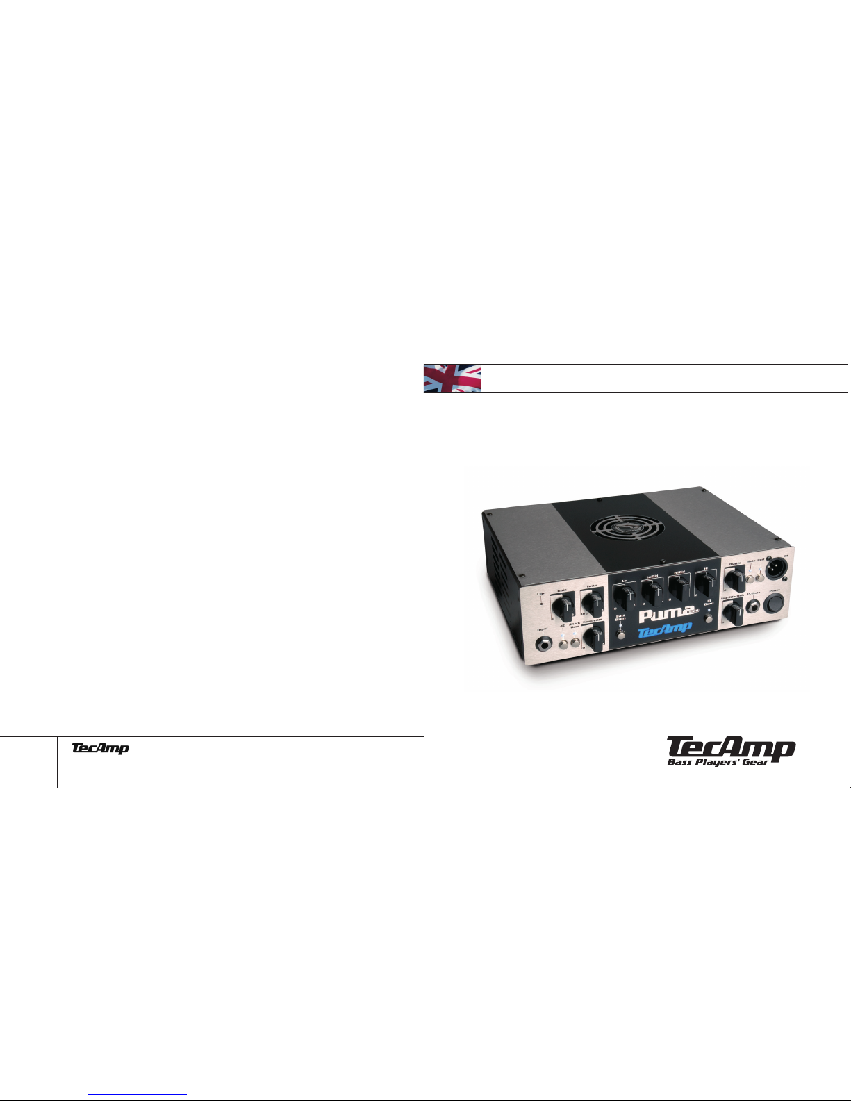
Puma 1000
>> Owner’s Manual – english
Alter Bahnhofsweg 5 · D-35745 Herborn
Congratulations! You are now the proud owner of a
TECAMP PUMA 1000 bass amplifier. This manual will
help you get to learn all the useful and exciting features
of one of the best amplifiers in the world.
The new TecAmp PUMA is extremely small in size but
very big in sound. Being a real TecAmp throughout only
the finest materials and components were chosen in
order to evenly reproduce the whole frequency range
and deliver a solid bass sound.
Exclusive features and our new ultra-flat premium input
stage set new standards in this amplifier class. The very
effective tone controls suit all musical styles. The amps
of the PUMA series boast a four-band tone control secti-
on which lets you easily dial any sound you want. The
TASTE control emphasizes the tonal characteristics of
the individual instrument. Set to the centre, the control
has no effect on the signal. Turn it counter-clockwise to
filter out some ultra-low frequencies and at the same
time enhance a pronounced mid range. This is the ulti-
mate fretless tone. Turn it clockwise to soften the high
end which leads to a pumping bass sound.
Additional features like an effects loop, Tuner Out, Line
Out, Line In, two Speakon®outputs and a DI out with
Pre/Post switch prove that the PUMA amps are extreme-
ly versatile machines. PUMA amps are ideal for travel-
ling around the world due to their voltage switch which
allows them to be operated at 230 and 115 volts.
PUMA 1000 as the top of the line features our newly
developed compressor which allows for subtle dynamic
alterations without any level changes. You can also
choose between a long and a short attack time which
gives you even more breathtaking sound variations. The
controls EFFECTS MIX and LINE IN are located on the
front panel and thus easily accessible. There is a foots-
witch jack for the MUTE function. The equalizer section
is further expanded by switchable bass and treble
boosts.
The result is an impressive live performance with an
unbeatable power-to-weight ratio. With its two indivi-
dually controllable digital power amps delivering 500
watts each (1000 watts in bridge mode) the PUMA 1000
will rumble any stage in the world.
The meticulous quality control during all stages of pro-
duction guarantees failsafe performance. Using only the
best components available the unique circuit design and
the professional workmanship make the PUMA 1000
today’s state-of-the-art in top-of-the-line bass amp
manufacturing.
>> Introduction
3
EG-Konformitätserklärung für das Produkt/Type
Puma Bassamp
Wir erklären in alleiniger Verantwortung als Hersteller, dass
dieses Produkt unter Beachtung der Betriebsbedingungen und
Einsatzumgebung laut Bedienungsanleitung mit den folgenden
Normen oder normativen Dokumenten übereinstimmt:
EN 61000-3-2, EN 61000-3-3, EN 55013,
EN 55020, EN 55022, EN 60065
gemäß den Bestimmungen der Richtlinien 89/336/EWG und
73/23/EWG.
2
The apparatus shall not be exposed to dripping or splashing and that
no objects with liquids, such as vases, shall be placed on the appa-
ratus. The MAINS plug is used as the disconnect device, the discon-
nect device shall remain readily operable.
Warning: the user shall not place this apparatus in the area during
the operation so that the mains switch can be easily accessible.
1. Read these instructions before operating this apparatus.
2. Keep these instructions for future reference.
3. Heed all warnings to ensure safe operation.
4. Follow all instructions provided in this document.
5. Do not use this apparatus near water or in locations where con-
densation may occur.
6. Clean only with dry cloth. Do not use aerosol or liquid cleaners.
Unplug this apparatus before cleaning.
7. Do not block any of the ventilation openings. Install in accordan-
ce with the manufacturer’s instructions.
8. Do not install near any heat sources such as radiators, heat regi-
sters, stoves, or other apparatus (including amplifiers) that produ-
ce heat.
9. Do not defeat the safety purpose of the polarized or grounding-type
plug. A polarized plug has two blades with one wider than the
other. A grounding type plug has two blades and a third grounding
prong. The wide blade or the third prong is provided for your safety.
If the provided plug does not into your outlet, consult an electrici-
an for replacement of the obsolete outlet.
10.Protect the power cord from being walked on or pinched particu-
larly at plug, convenience receptacles, and the point where they
exit from the apparatus.
11.Only use attachments/accessories specified by the manufacturer.
12.Use only with a cart, stand, tripod, bracket, or table specified by
the manufacturer, or sold with the apparatus. When a cart is
used, use caution when moving the cart/apparatus combination
to avoid injury from tipover.
13.When a cart is used, use caution when moving the cart/appara-
tus combination to avoid injury from tipover.
14.Unplug this apparatus during lighting storms or when unused for
long periods of time.
15.Refer all servicing to qualified service personnel. Servicing is
required when the apparatus has been damaged in any way, such
as power-supply cord or plug is damaged, liquid has been spilled
or objects have fallen into the apparatus, the apparatus has been
exposed to rain or moisture, does not operate normally, or has
been dropped.
CAUTION: USE OF CONTROLS OR ADJUSTMENTS OR PERFOR-
MANCE OF PROCEDURES OTHER THAN THOSE MAY RESULT IN
HAZARDOUS RADIATION EXPOSURE.
WARNING: TO REDUCE THE RISK OF FIRE OR ELECTRIC SHOCK, DO
NOT EXPOSE THIS APPARATUS TO RAIN OR MOISTURE.
CAUTION: RISK OF ELECTRIC SHOCK DO NOT OPEN
CAUTION: TO REDUCE THE RISK OF ELECTRIC SHOCK, DO NOT
REMOVE COVER (OR BACK) NO USER SERVICEABLE PARTS INSIDE
REFER SERVICING TO QUALIFIED PERSONNEL
The lightning flash with arrowhead symbol, within
an equilateral triangle, is intended to alert the user
to the presence of uninsulated “dangerous voltage”
within the product’ s enclosure that may be of sufi-
cient magnitude to constitute a risk of electric shock
to persons.
The exclamation point within an equilateral triangle
is intended to alert the user to the presence of
important operating and maintenance (servicing)
instructions in the literature accompanying the
appliance.
!
IMPORTANT SAFETY INSTRUCTIONS
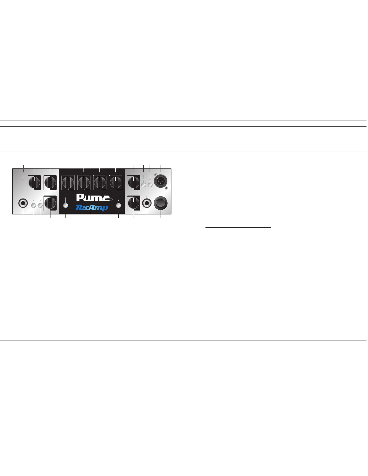
>> Front Panel
1 INPUT
Plug in your shielded instrument cable into this jack. We
advise you to always turn down the volume control on
your instrument before plugging it into this jack.
2 -10
When using a bass guitar with active pickups or basically
delivering relatively high output levels we advise you to
use this function. When this switch is engaged the signal
will be attenuated by 10 dB before it reaches the GAIN
and TONE controls. This mode is accompanied by an illu-
minated blue LED above the switch. Attenuation allows
the “GAIN” control (#4) to be used in a more subtle way
by somehow altering the taper of the pot – the “GAIN”
control can be brought up to a higher position now.
If, on the other hand, the GAIN control must be turned all
the way up without reaching a satisfying gain range, you
better deactivate the “-10 dB” switch.
3 CLIP
The red CLIP LED helps you adjust the input sensitivity of
the PUMA 1000 preamp so that the signal from your
instrument best matches the preamp’s internal operating
level. Turn up the GAIN control (#4) while you hit the
strings of your bass hard until the CLIP LED starts flas-
hing. Now back up the GAIN control a bit until the LED
goes off. The flashing CLIP LED tells you that the input
stage of the preamp is clipping somewhere and that you
should either turn down the GAIN control (#4) or engage
the –10 dB function (#2). Keep in mind that excessive
use of the LO control (#9) and BASS BOOST (#8) will
raise the internal level and thus make the CLIP LED come
on much earlier.
4 GAIN
This control adjusts the basic signal level in the preamp
and thus determines it’s sensitivity and overall dynamic
characteristics. In order to best adjust your instrument’s
signal level to the internal operating level of PUMA 1000
watch the CLIP LED (#3). Set the GAIN and/or the –10 dB
function (#2) such that the CLIP LED just doesn’t come up.
Do not leave the volume control on your instru-
4
ment set too low, otherwise noise picked up along the
cable will become more prominent and thus lower the
signal-to noise ratio of the amp.
5 TASTE
This unique feature adds to the superiority of the PUMA
1000’s tonal qualities. Leave the control in the centre
position if you seek a more “natural” sound. When tur-
ned to the right (clockwise) towards “RICH” the sound
gets increasingly fatter with lots of low-end punch,
ending in a warm, vintage-like tone. When turned to the
left (counter clockwise) towards “DRY” this control adds
urgent attack and midrange growl.
The “TASTE” control allows you to quickly and
effectively soften those instruments which sound a litt-
le harsh and scathing. At the same time bass guitars
with a muddy, booming neck pickup gain definition by
turning the “TASTE” control towards the “DRY” position.
6 ATTACK TIME
This switch allows you to alter the attack time of the
included high-end “COMPRESSOR” (#7). When the
switch is not engaged the attack time is short which
means that the signal is compressed immediately –
great for fretless sounds. When you depress the switch,
which is accompanied by an illuminated LED above it,
the attack time is longer. Now the transients of the
signal (the very first moments of a note) pass the circuit
unprocessed resulting in a hot, lively bass sound – great
for rock and funk sounds.
7 COMPRESSOR
The “COMPRESSOR” of the PUMA 1000 gently pulls up
low notes, thus providing a great, even sustain. The
more you turn up the “COMPRESSOR” (to the right, i.e.
clockwise), the more audible is the compression effect.
The level reduction usually associated with compression
is made up by an internal automatic gain control. No
matter how much compression you apply the signal level
will always stay the same. In order to use the compres-
sor conveniently and effectively adjusting the input sen-
sitivity (refer to #1 through #4)is of crucial importance.
8 BASS BOOST
This switch, when engaged (the associated LED above
illuminates), boosts the very low frequencies around 30 Hz
by 12 dB. This adds a solid ground to the sound similar to
a valve amp.
9 LO
This is the primary low frequency control. It allows for cut-
ting or boosting the frequency range around 70 Hz by 15 dB
each. This frequency range represents the bottom end and
massive yet distinguished punch in a bass guitar. Start
from the 12 o’clock position and dial in the sound you like.
10 LO MID
The “LoMID” control is centred at 250 Hz and offers a cut
or boost of 12 dB. The slope of this control is not as
steep as the one of the “LO” control (#9). This frequency
range, when turned up, determines the body of the bass
guitar signal and lets the bass be heard in a mix. Turn it
counter clockwise to reduce unwanted room resonance.
11 HI MID
The “HiMID” control is centred at 800 Hz and offers a cut
or boost of 12 dB, again with a more gentle slope just
like the “LoMID” control (#10). Due to the broader ran-
ges which are covered by these controls the sound never
gets booming or honky when you turn them all the way
up. Turning up the “HiMID” control gives you a great fret-
less sound. On the other hand, when you cut the HiMID
range you end up with a funky slap sound of extremely
high quality.
5
NTIPS & TRICKS FROM DR. BASS
NTIPS & TRICKS FROM DR. BASS
Input
Gain Taste Lo LoMid HiMid Hi Master
Line/EffectMix
MuteClip
Power
Post
-10
10
010
0
10
0
10
0Rich
Dry 10
010
010
010
0
Compressor
Bass
Boost
Hi
Boost
Attack
Time
DI
FS/Mute
1000
1
3 4 5 9 10 11 12 15 16 17 18
2 6 7 8 13
21 14 20 19

6 7
12 HI
The “HI” control is centred at 5 kHz and offers a cut or
boost of 15 dB. Turn it up for a biting, crystal clear rock
or funk bass. Turn it counter clockwise to reduce hiss or
generally dampen the sound for a muted reggae feel.
13 HI BOOST
Depress this switch and engage a boost of 12 dB at 10
kHz. The LED above will illuminate. This is your switch if
your strings are dead or if you are into a more HiFi-like
bass sound with silky top end.
14 LINE/EFFECT MIX
Signals connected to the “LINE IN / EFFECTS LOOP
RETURN” jack (#26a) can be added to the dry bass guitar
signal according to your likings with this “LINE/EFFECTS
MIX” control. The parallel “EFFECTS LOOP” (#26) is desi-
gned for the connection of one or more effects devices.
The “RETURN/LINE IN” jack (#26a) can also be used to
connect various external audio sources to the PUMA
1000 such as an MP3 player, a second bass guitar, or in
order to just use the power amp of the PUMA 1000.
The “LINE / EFFECTS MIX” is a balance control adjusting
the level of the effects sound as compared to the dry
sound of the PUMA 1000 preamp. With the “EFFECTS
MIX” control all the way to the left the signal of the
external device, i.e. of the “RETURN” jack (#26a), is off.
All you hear is the dry bass signal. Turning it up a little
will add some effects to your sound. In this position (to
the left of the knob’s centre position) the effects sound is
processed in parallel with the unaffected or dry signal
which enables you to preserve the integrity of the pre-
mium tone and feel the PUMA 1000 is capable of delive-
ring.
The more you turn the control clockwise, the more pro-
minent will the “RETURN” signal become (i.e. the effect)
while at the same time the dry signal will decrease.
When the “MIX” control is turned all the way up to the
“WET” position the EFFECTS loop effectively becomes a
serial loop. Now the internal signal path is interrupted
(rather than just tapped), sent out to the external devi-
ce(s) where it gets processed (added with effects, modu-
lated, modified, whatever) and returned to the amplifier
as a whole.
15 MASTER
This is the overall volume control of the PUMA 1000 and
works on the two internal power amp sections. It deter-
mines the level at the “SPEAKER OUTPUTS” (#27 - #29)
as well as the “LINE OUT” jack (#25).
Note: Each power amp features its individual “VOLUME”
control on the back panel (#28a and #29a). Do make sure
that they are turned up accordingly.
16 MUTE
The “MUTE” switch should be depressed when you
power up or down your PUMA 1000 – the LED above the
switch illuminates when the function is engaged. In this
mode no audio signal will be processed and heard at any
output except the “TUNER” jack (#24). That way you
don’t have to turn down the volume for silent tuning or
when changing instruments, thus you do without the
nasty cling which you usually hear when you unplug the
jack.
The “MUTE” switch also interrupts the signal path at the
balanced “DI OUT” (#18), no matter which position the
switch “POST” (#17) is in (that way your silent tuning or
changing instruments won’t be heard in the PA, either).
During breaks the amp should be set to “MUTE” rather
than switched off completely. That way the internal fan
stays on and cools down the power amp circuitry if
necessary. Disengage the “MUTE” function and start to
rumble – now there is signal at all outputs again.
17 POST
With this switch the balanced “DI OUT” (#18) can be
>> Front Panel
selected to be a “PRE” or “POST” preamp signal. In the
“PRE” position (switch is not depressed) the “DI OUT”
signal is tapped directly after the input stage including
the “-10 dB” function (#2), if activated, as well as the
“GAIN” control (#4).
In the “POST” position (switch depressed) the “DI OUT”
signal is taken after it has been processed by the com-
plete preamp, i.e. including the “GAIN” control (#4), the
tone control section (#8 through #13), and the “EFFECTS
LOOP” (#14, #26). It is not affected by the “MASTER”
control (#15). As a reference the LED above the “POST”
switch illuminates when the “DI OUT” is set to “POST”.
18 DI
PUMA 1000 supplies a balanced line output signal for
connecting to a house mixing board, recording console or
external amplifier(s) with balanced inputs. Connect a
shielded 3-core microphone cable with XLR plugs to this
male XLR output.
The need for an additional active DI box, which can be
pretty expensive, is obsolete. Due to the advanced cir-
cuit design using only the best components available the
high sound quality of the “DI OUT” makes it the amp of
choice in any recording studio (you can use the PUMA
1000’s pre amp on its own without driving any speakers).
The DI signal can be tapped either before or after the
preamp, as determined by the switch “POST” (#17).
There is no need to be afraid of nasty ground loops as
the DI output is soft-grounded.
19 POWER
At the risk of stating the obvious, this stylish yet heavy-
duty rocker switch is used to turn the PUMA 1000 on and
off. Before you turn on the amp do make sure that the
“MUTE” switch (#16) is depressed. Activating the
POWER SWITCH (the top of the switch must be depres-
sed towards the amp chassis) will make the TECAMP
logo on the front panel (#21) illuminate. The amp is OFF
when the bottom of the POWER SWITCH is depressed –
the logo will no longer illuminate.
20 FS/MUTE
Connect the optional footswitch FSP1 to this 6.3 mm
mono jack with cable which comes included with the
switch. This will allow you to remotely switch the
“MUTE” function (#16). When the function is engaged
the eye of the puma on the footswitch will illuminate
red.
For the footswitch to work effectively do make sure that
the “MUTE” switch on the front panel of the amp (#16)
is not engaged.
21 TecAmp Logo
The TECAMP logo in the centre of the front panel will
illuminate blue when the PUMA 1000 is switched on,
provided the included power strip is plugged into the
“POWER RECEPTACLE” on the back panel (#22) and the
“POWER” switch (#19) is turned on.

24 TUNER
This jack is provided for connection to an electronic
tuner and is always “live” even when the PUMA 1000 is
in “MUTE” mode (#16). This allows for silent tuning as
well as providing a monitor feed which stays hot even
when the house mix is muted.
25 LINE OUT
This jack provides a line level signal for connection to a
separate power amp, PA mixing console or recording
equipment. The volume of the signal is controlled by the
“MASTER” control (#15). Note that the output is muted
when the “MUTE” function (#16) is engaged.
26 EFFECTS LOOP
SEND, RETURN / LINE IN
These two 1/4” jacks are the patch points for external
signal processing effects. This loop can be both serial
and parallel depending on the position of the “EFFECTS
MIX” control on the front panel (#14).
26b SEND
Connect the “SEND” jack to the input of the (first) exter-
nal device.
26a RETURN / LINE IN
Connect the output of the (last) external device to the
“RETURN” jack. The “EFFECTS MIX” control (#14) allows
you to variably balance the level of your dry instrument
signal with the wet effects signal.
Whether you hook up an effects device in parallel or
serial depends on the effect itself. Time related effects
such as reverb, delay and modulation effects are usually
hooked up in parallel, while volume related effects such
as an equalizer, compressor etc. should be hooked up in
serial.
Always use high quality shielded instrument cables for
connecting to and from external devices. Keep the
cables as short as possible. If you notice crackling dis-
tortion when using external effects, either the batteries
of the stomp box have run out, or the send level of the
amplifier is too high for the processor’s input stage. In
this case you better connect the device between bass
guitar and amplifier.
The “RETURN / LINE IN” jack (#26a) can also be used to
connect various external audio sources to the PUMA
1000 such as an MP3 player, a second bass guitar, or in
order to just use the power amp of the PUMA 1000. You
are now able to mix this external audio signal with your
instrument signal. The “MASTER” control (#15) determi-
nes the final output level (watch the “VOLUME” controls
of the individual power amps as well, see #28a and
#29a). As the “RETURN / LINE IN” jack (#26a) is placed
after the tone controls (#8 through #13) you can adjust
the sound of your instrument connected to the “INPUT”
(#1) to your likings without affecting the sound of the
external audio source. This way you can jam along your
favourite playbacks.
27 SPEAKER BRIDGED MODE
PUMA 1000 sports three Neutrik Speakon®NL4 MP
speaker outputs. The wiring of the pins is as follows: 1+
= hot, 1- = ground. The one on the right (looked from
behind) is reserved for mono bridged operation. When
operating the amp in MONO BRIDGE MODE care should
be taken that the minimum load is no less than 8
ohms.
27a BRIDGE ON / OFF
Press the switch “BRIDGE ON/OFF” just above this Spea-
kon®output until it rests in the “ON” position. In this
mode neither the two “VOLUME” controls for “CHAN-
NEL A” (#29a) and “CHANNEL B” (#28a) nor the “SUB-
BOOST” filter (#28b) are active. The overall output level
is controlled by the “MASTER” volume control (#15) on
the front panel only. Make sure that the speaker outputs
22 POWER RECEPTACLE
Connect the supplied AC power cord to the power recep-
tacle. Make sure the Euro plug is firmly inserted in the
socket. The other end of the cable should be connected
to any standard grounded AC outlet or into a power strip
of proper voltage. Before you plug in do make sure that
the voltage is correct (see #23)!
Just in case you lose the cord provided, the jack accepts
a standard 3-prong IEC cord like those found on most
professional gear and computers – you can get it at any
electronics, music or computer store.
Never (!) remove or otherwise attempt to defeat
the ground pin of the power cord in order to get rid
of a hum induced by a ground loop.
22a POWER FUSE
The PUMA 1000 is fused for your and its own protection.
If you suspect a blown fuse, disconnect the cord, pull out
the FUSE DRAWER (#22a, located just below the cord
receptacle) and replace the fuse with another suitable
fuse. There should be a spare fuse in the fuse drawer.
For 230 V units the fuse for the PUMA 1000 must be a 4
A (amps) SLO BLO 5 x 20 mm. When you’re in a country
with a standard of 115 volts set the “VOLTAGE SELEC-
TOR” (#23) accordingly and don’t forget to change the
fuse to 6.3 A SLO BLO.
If two fuses blow in a row, something is very wrong. Do
not open the unit. Refer service to qualified service per-
sonnel.
23 VOLTAGE SELECTOR
The PUMA 1000 features a “VOLTAGE SELECTOR” allo-
wing you to use your amplifier anywhere in the world
just by the flick of a switch. The unit is set to 230 V when
we ship to a country in Europe.
Should you wish to use your PUMA 1000 in the USA set
the “VOLTAGE SELECTOR” to “115 V” and replace the
fuse in the fuse drawer (#22a) by a 6.3 A SLO BLO.
ATTENTION: Don’t forget to set it back to “230 V”
and change the fuse when you return home!
TecAmp cannot be made responsible for damages
to the unit caused by improper voltage selection.
Therefore it is a good idea to always check the
“VOLTAGE SELECTOR” before powering up the unit.
-10 0
VOLUME
-10 0
VOLUME SUB
VOLTAGE
115 V230 V
OFF
ON
OFF
ON
USE ONLY WITH A 250V FUSE
230
N
E
U
T
R
I
K
N
E
U
T
R
I
K
N
E
U
T
R
I
K
SEND
EFFECTS LOOP
RETURN LINE OUT
LINE IN
TUNER
Made in Germany
!
HIGH VOLTAGE!CAUTION: TO PREVENT
THE RISK OF FIRE AND SHOCK HAZARD
DON’T EXPOSE THIS APPLIANCE TO
MOISTURE OR RAIN. DO NOT OPEN CASE.
NO USER SERVICEABLE PARTS INSIDE.
REFER SERVICING TO QUALIFIED
SERVICE PERSONNEL.
MIN. 4 ΩMIN. 4 ΩMIN. 8 Ω
CHANNEL ACHANNEL BBRIDGED MODE
>> Back Panel
8 9
23 29a 28a 27a
22 22a 29 28
28b
27 26b 26a 25 24

>> Back Panel
of “CHANNEL A” (#29) and “CHANNEL B” (#28) are not
being used.
In MONO BRIDGE MODE the two internal power amps
are combined to produce 1000 watts of continuous out-
put power at a minimum load of 8 ohms. Be absolutely
certain that the speaker cabinet(s) connected is (are)
able to handle the extremely high output power of the
amp. All TECAMP cabinets featuring at least 4 speakers
will do the job easily (e.g. L410-8, XL412-8, L610-8, etc.).
When you use a speaker cabinet with a lower power
handling capacity do make sure that you operate the
amp at moderate levels only, i.e. don’t turn up the
“MASTER” control (#15) too far.
Whatever your setup is, always make sure that
the speaker cables are as long as necessary but as short
as possible, using heavy gauge cable (we recommend at
least 2 x 2.5 mm2). Do stick to speaker cables with
Speakon
®
connectors only, either NL2FC (two pin con-
nector) or NL4FC (four pin connector). The wiring of the
pins is as follows: 1+ = hot, 1- = ground.
High quality TECAMP speaker cables can be obtained as
an option.
28 Speaker – CHANNEL B
PUMA 1000 is equipped with two power amps, CHAN-
NEL A and CHANNEL B, which can be used simultane-
ously, each of them delivering 500 watts continuous out-
put power at a minimum load of 4 ohms. Each power
amp features one Neutrik Speakon®connector. If you
want to connect more than one speaker cabinet to the
SPEAKON®outputs you have to daisy chain one cabinet
with the next. Just make sure that the minimum load
of each power amp is no less than 4 ohms.
CHANNEL A works exactly the same way as CHANNEL B.
Thus, in total, you could connect two cabinets with an
impedance of 4 ohms each or four cabinets with an impe-
dance of 8 ohms each to the PUMA 1000 simultaneously.
28a VOLUME
Both power amp channels have got their own “VOLUME”
control (#28a and #29a). They allow you to set individual
output levels for the cabinets connected thus leaving you
with a couple of interesting options. Do make sure that
the “BRIDGE ON / OFF” switch (#27a) is in the “OFF” posi-
tion – otherwise these “VOLUME” controls are not active.
28b SUB ON / OFF
“CHANNEL B” features a unique “SUB BOOST” filter doing
two different things simultaneously: When this switch is
depressed a low pass filter cuts all frequencies above 200
Hz. At the same time there is a level boost of 12 dB.
This switch makes your PUMA 1000 the ideal amp for the
use with a TECAMP PLEASURE BOARD together with a
“normal” cabinet. Connect the Pleasure Board to “CHAN-
NEL B” (#28) with the “SUB BOOST” function depressed
and a “normal” speaker cabinet to “CHANNEL A” (#29)
while balancing the output levels accordingly.
29 Speaker – CHANNEL A
CHANNEL A works exactly the same way as CHANNEL
B with the exception of not offering the “SUB” filter.
Thus you can connect one or two speakers (by daisy
chaining them) with a total impedance of 4 ohms. The
output power rating is 500 watts. CHANNEL A and
CHANNEL B can be operated simultaneously.
29a VOLUME
“CHANNEL A”, just like CHANNEL B, features its own
“VOLUME” control. It allows you to adjust individual out-
put levels for both channels and thus the cabinets con-
nected. Do make sure that the “BRIDGE ON / OFF”
switch (#27a) is in the “OFF” position – otherwise this
“VOLUME” control is not active.
30 RACK MOUNTING
The two included rack ears allow you to install your
PUMA 1000 in a standard 19” rack, if desired. It will
occupy two rack units. Each rack ear (there is a left and
a right version) is fixed to the chassis using the three
screws on either side which come included with the unit
(when shipped the screws are fixed to the amp). Uns-
crew them, hold the rack ears in place and fix them tight-
ly with the three screws respectively.
10 11
Technical Specifications Puma 1000
input impedance 1 meg ohms
sensitivity -26 dBu max.
effects loop impedance:
effect send 600 ohms
effect return / line in 10 k ohms
nominal input level 0 dBu
line out impedance 600 Ohm
nominal output level line out +6 db
impedance balanced DI output 600 ohms
nominal output level DI out +6 dBu
compressor attack time:
short 5 ms
long 25 ms
tone control section:
bass boost +12 dB @ 30 Hz
lo +-15 dB @ 70 Hz
lo mid +-12 dB @ 250 Hz
hi mid +-12 dB @ 800 Hz
hi +-15 dB @ 5 kHz
hi boost +12 dB @ 10 kHz
output power rating:
channel A 500 watts @ 4 ohms
channel B 500 watts @ 4 ohms
mono brigde mode 1000 watts @ 8 ohms
fuse:
230V/AC 4 A/T (slow blow)
115V/AC 6,3 A/T (slow blow)
dimensions (W x H x D):
27 x 8 x 25 cm; 10,6” x 3,1” x 10”
weight: 2,8 kg; 6,2 lbs
NTIPS & TRICKS FROM DR. BASS
-10 0
VOLUME
-10 0
VOLUME SUB
VOLTAGE
115 V230 V
OFF
ON
OFF
ON
USE ONLY WITH A 250V FUSE
230
N
E
U
T
R
I
K
N
E
U
T
R
I
K
N
E
U
T
R
I
K
SEND
EFFECTS LOOP
RETURN LINE OUT
LINE IN
TUNER
Made in Germany
!
HIGH VOLTAGE!CAUTION: TO PREVENT
THE RISK OF FIRE AND SHOCK HAZARD
DON’T EXPOSE THIS APPLIANCE TO
MOISTURE OR RAIN. DO NOT OPEN CASE.
NO USER SERVICEABLE PARTS INSIDE.
REFER SERVICING TO QUALIFIED
SERVICE PERSONNEL.
MIN. 4 ΩMIN. 4 ΩMIN. 8 Ω
CHANNEL ACHANNEL BBRIDGED MODE
23 29a 28a 27a
22 22a 29 28
28b
27 26b 26a 25 24
Table of contents
Other Tecamp Musical Instrument Amplifier manuals


