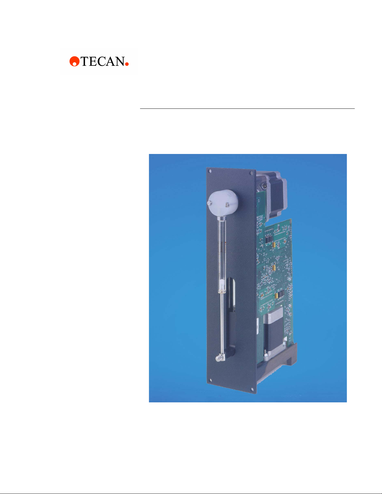
Cavro® XLP 6000 Modular Syringe Pump Operating Manual, 734237-C, en
Copyright © 2005 Tecan Systems, Inc.
Part Number 734237-C
Copyright and Trademark Information
Teflon®is a registered trademark of E.I. DuPont de Nemours & Co., Inc.
Kel-F®is a registered trademark of the 3M Company
CONTRAD®is a registered trademark of Decon Laboratories, Inc.
Microsoft Windows®, Windows 3.1®, Windows 95®, Windows NT®, and Windows
2000®are registered trademarks of Microsoft Corporation.
Cavro®is a registered trademark of Tecan Systems, Inc.
Product Warranty Information
Tecan Systems warrants that instruments manufactured and sold by Tecan
Systems will be free from defects in materials and workmanship for a period of
twelve (12) months from the date of shipment to customer. Tecan Systems’
liability for the breach of the foregoing warranty is limited to the repair or
replacement of the products found to be other than warranted. Such products will
be accepted for return only if the customer returns them to Tecan Systems’
factory or repair depot within thirty (30) days from the time of discovery of the
alleged defect, and prior to return, fills out a Certificate of Decontamination
(document P/N 730171), obtains a return authorization number from Tecan
Systems, provides Tecan Systems with the serial number of each instrument to
be returned, and prepays freight charges to the factory or a designated Tecan
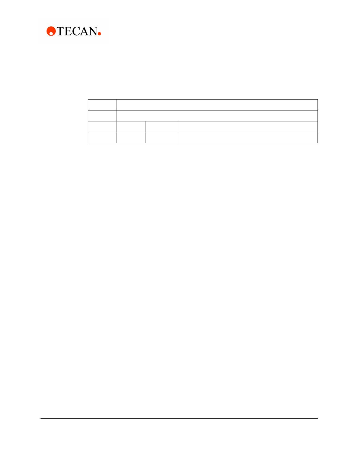
Systems repair depot. No warranty is expressed or implied for:
The foregoing warranties and limitations are customer’s exclusive remedies and
are in lieu of all other warranties, express or implied, including without limitation
any warranty of merchantability or fitness for a particular purpose.
Product Documentation Warranty Information
The information contained in this document is subject to change without notice.
Tecan Systems makes no warranty of any kind with regard to this material,
including, but not limited to, the implied warranties of merchantability and fitness
for a particular purpose.
Tecan Systems shall not be liable for errors contained in this document or for
incidental or consequential damages in connection with the furnishing,
performance, or use of this material.
Breakage Syringes
Maltreatment Syringe seals
Unauthorized service Tubing and tubing
connections
Units not returned in original or
adequate packaging Cavro valves
Units which are “life-cycled” Cavro probes