Technicolor - Thomson ICC19 Instructions for use
Code : 3504.93.50 - 07/97 - ICC19 CHASSIS TELEVISION SETS: PRINCIPLES AND MAINTENANCE.
No copying, translation, modification on other use authorized. All rights reserved worldwide. • Tous droits de reproduction, de traduction, d'adaptation et d'exécution réservés pour tous les pays. • Sämtliche Urheberrechte an diesen Texten und Zeichnungen stehen uns zu. Nachdrucke,
Vervielfältigungen - auch auszugsweise - nur mit unserer vorherigen Zustimmung zulässig. Alle Rechte vorbehalten. • I diritti di riproduzione, di traduzione, e esecuzione sono riservati per tutti i paesi. • Derechos de reproduccion, de traduccion, de adaptacion y de ejecucion reservados para todos lospaises.
ICC19 CHASSIS TELEVISION SETS:
PRINCIPLES AND MAINTENANCE
50-Hz CHASSIS
100-HzCHASSIS

2
MENUS
NAVILIGHT


CONTENTS
GENERAL INFORMATION-----------------------------------------------------------------------------------------3
MANAGEMENT------------------------------------------------------------------------------------------------------- 5
POWER SUPPLY ---------------------------------------------------------------------------------------------------23
TIME BASES------- ------------------------------------------------------------------------------------------------- 57
HIGH FREQUENCIES/MEDIUM FREQUENCY------------------------------------------------------------ 73
SWITCHING --------------------------------------------------------------------------------------------------------- 79
50-HZ VIDEO-------------------------------------------------------------------------------------------------------- 89
100-HZ VIDEO----------------------------------------------------------------------------------------------------- 103
VIDEOTEXT AND OSD ----------------------------------------------------------------------------------------- 125
RGB AMPLIFIERS------------------------------------------------------------------------------------------------ 129
AUDIO PROCESSING ------------------------------------------------------------------------------------------ 133
DOLBY PROLOGIC --------------------------------------------------------------------------------------------- 139
1

2

3
GENERAL INFORMATION

4

MANAGEMENT
CONTENTS
• IR001 POWER SUPPLY AND OPERATIONAL SIGNALS
• DATA MANAGEMENT
• CONTROLS
• RMICROCONTROLLER/EPROM COMMUNICATION
• BUSES
• BUS EXPANDER
• OTHER CONTROLS
• SWITCH-ON PROCEDURE
• FRONT PANEL LED CONTROL
• OFF/ON TIMING DIAGRAM
• ERROR CODES
CENTRE DE
FORMATION TECHNIQUE
5
5

6
6
IP130
DP130 DP133
CP130 CP141
DP134
IP140
REGULATOR
5V
CP142
+5V
IR001
ST90R92
TDA8139
CR009 CR010
QR001
27MHZ
46 48
9
6
3
49
23
RP147
40ms
1
MC7812
LP020
17
18
13V (L)
VCC
RESET
3v
123
RESET
CENTRE DE
FORMATION TECHNIQUE

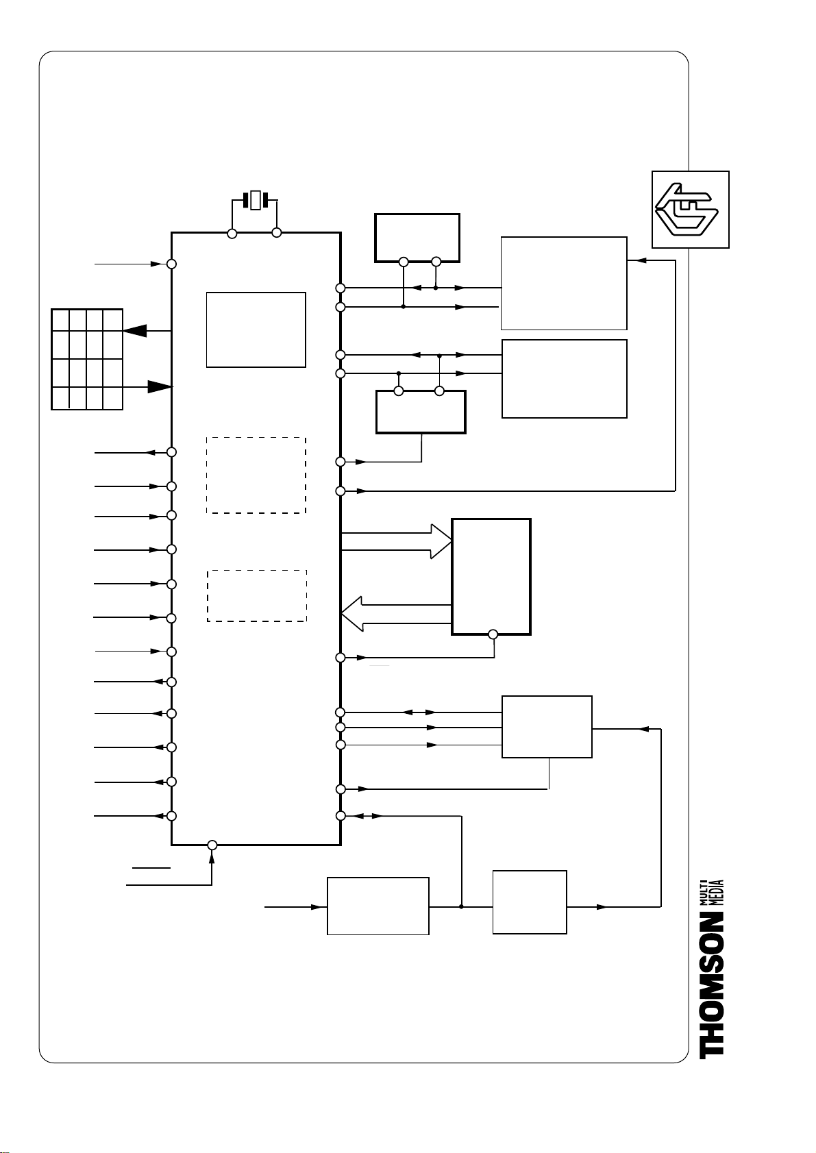
IR001 POWER SUPPLY AND OPERATIONAL SIGNALS
POWER SUPPLY
The power supply to the microcontroller at Pin 23 is active when the IP130
regulator (which produces a 10VSTBY) and the IP140 regulator (which
produces a 5VSTBY from the 10VSTBY) are on Standby. When they are On,
the 13 V (LINE) supply takes over from the 10VSTBY.
CLOCK.
A 27-MHz QR001 quartz stabilises the system clock of the IR001
microcontroller (Pins 46 and 48).
RESET.
CP142, Pin 3 of the IP140 is the Reset capacitor. When the voltage at Pin 9 of
the IP140 has reached 5 V, and after a delay of a few milliseconds given by
CP142, Pin 6 of the IP140 goes from 0 to 5 V. Pin 49 of IR001 receives this
Reset signal.
NOTES :
CENTRE DE
FORMATION TECHNIQUE
7
7
8
8
RESET
+5VSTBY
RIR
STB-LED
CLAVIER
LDR
AFC
AV1
AV2
MUTE
MUTE C
SAT_ON_DEG
FB_DET
TV OFF
ZOOM
E-FIELD
I2C-1
I2C-2
SND-RESET
INT
BUS M3L
IR001
ST90R92
EEPROM
IR003
IR004
BE_STROB
EPROM
IR002
256 Ko
4 Ko
Expander
RAM
REGISTRES
TIMER
SAFETY
Bus µp
QR001
M-RESET
POWER-FAIL
Alim.
VIDEOTEXT
DEFLECTION
VIDEO MATRIX
PIP MODULE
DOLBY SOUND
TUNER CCT5000
CHROMA 1H / 2H
PSI 2H
MEGATEXT
VIDEO MODULE
100HZ
MODULE
27MHZ
MARK-E-TING
Data
Addresses
DS
46 48
23
51
53
43
42
44
45
62
52
54
27
40
41 49 55
28
63
64
65
25
39
29
33
32
31
34
VIDEO ADJUSTMENT
CENTRE DE
FORMATION TECHNIQUE
DATA MANAGEMENT
ICC19 chassis are 50-Hz or 100-Hz compatible. They are controlled by an 8-
bit microcontroller, the ST90R92.
It communicates via an address and data bus with its external program
memory, an EPROM, IR002, with a basic capacity of 256 KB that can be
extended to 1024 KB.
Two I2C buses dialog with the various programmable circuits installed on the
chassis.
In conjunction with IR003 (EEPROM), the I2C1 bus saves the parameters and
settings required by the television set.
It manages the ON/OFF command, the line and frame time base circuits, audio
and video switching, and settings including the USYST voltage.
In conjunction with the tuner frequency synthesis, the I2C2 bus controls video
processing and the 100-Hz digital converter.
It also controls an 8-bit IR004 universal register (EXPANDER), which increases
the number of control ports.
The M3L bus is intended for the TELETEXT module (MEGATEXT version).
The microcontroller analyses and distributes the commands from peripheral
devices, the infrared receiver, the keypad, and the red LED via several input
and output lines.
The INT line is the HALT input of the microcontroller, and the MAIN RESET
output of the TELETEX module.
NOTES :
CENTRE DE
FORMATION TECHNIQUE
9
9

10
10
A
B
C
D
58
59
60
53
VOL+
VOL-
PROG+
PROG-
INSTALL EXIT
MENU
MUTE
INFO
RR
039
RR
040 RR
038
RR037
RR045
RR032
RR033
RR034
RR035
RR044
5VSTBY
5VSTBY
RIR
IR001
KEY OUT
KEY IN
RR924
OPTION
35
36
37
38
CENTRE DE
FORMATION TECHNIQUE

CONTROLS
KEYPAD
The keypad is compatible with previous ICC10/11 chassis. It can support four
to 10 control keys. It is laid out in a matrix of rows and columns.
Pins 58 through 60 are the function inputs. They are at 5 V when idle. Pins 35
through 38, which are labelled A, B, C, and D, are the sweep outputs. Signals
with a period of 20 ms are present on these outputs when idle.
During the initialisation phase, Line C (Pin 36) is connected to the input and
analysed. In this way, an option prediction, determined by Resistor RR924, can
be read.
The four diodes protect the IR001 circuit inputs.
REMOTE CONTROL UNIT
LRemote control function codes (12 bits) arrive at Pin 53 of IR001. They consist
of the following:
• Four address bits,
• One call bit,
• Seven function bits, defined by the key pressed.
These codes are repetitive at 80-ms intervals.
NOTES :
CENTRE DE
FORMATION TECHNIQUE
11
11

12
12
BS05
BS04
BS01
BS00
15 bits
8 bits
A0 - A14
D0 à D715 à 22
25 24
Data strobe line DS
16
17 à 21
5VSTBY
1 - 32
14
13
3
2
30
31
57
56
1 à12
et
66 à 68
4 à 12
23
25 à 29
13 à15
IR002
EPROM
IR001
µ C
CENTRE DE
FORMATION TECHNIQUE

REMOTE CONTROL UNIT
ADDRESSING
The IR002, memory for the software and default values, is an EPROM with
capacity up to 512 KB or 4 Mbits.
The 8-bit ST90R92 microcontroller has an address bus (A0-A14) limited to 15
bits. This provides addressing of only 32 KB. Page-swapping is therefore
necessary.
Four output port lines (BS00 through BS05) swap the read-only memory for a
selection of 16 pages compatible with the use of an 8-Mbit memory capacity,
i.e. 1024 KB.
DATA
Data comprising eight bits, labelled D0 through D7, are sent via the data bus.
To prevent any conflict of addresses with the microcontroller internal RAM, an
enable line, called data-strobe, is activated in the low state when the
microcontroller communicates with its ROM. The rest of the time, the IR002 is
in tri-state to free the data bus.
NOTES :
CENTRE DE
FORMATION TECHNIQUE
13
13

14
14
IR004
REGISTER
MC14094
IR003
EEPROM
M24C32
DR104
9,1V
RR
010
RR
011
+5VSTBY 13V L
M3L-CK
M3L-DA
M3L-ENAB
63
64
65
32
31
34
33
29 BE-STROBE
2
SDA
SCL
SDA
SCL
RR055
RR056
+5V
+5VSTBY
RR052RR053
IR001
1
11
8
14
6
3
12
13
16
15
5V
BG_INFO
L1_INFO
I_INFO
IIC2
IIC1
DEGAUSS
NORM
TUNER
VIDEO MODULE
PERITEL
AUDIO
IV001
87
56
VIDEOTEXT
TR095
µc
PIP
MEGATEXT
RR
012
CENTRE DE
FORMATION TECHNIQUE

BUSES
The IIC1 bus is charged by pull-up resistors connected to the +5VSTBY. It is
active in Standby and On Modes.
It dialogs with the IR003 NVM (M24C32) to store the user parameters.
It distributes its commands to the SCART switching circuits, the Audio Module,
and the sweep and video processor (IV001).
The IIC2 bus, referenced by pull-up resistors connected to the +5V, is active in
On Mode only.
It communicates directly with the PLL built into the tuner. It controls the Video
Module as well as the IR004 expander circuit.
The M3L bus is used in controlling the Teletext or Megatext Module.
BUS EXPANDER
Integrated Circuit IR004 (MC14094) is an 8-bit serial/parallel register that
extends the interface capacity of the microcontroller.
It is equipped with a de-serialiser register and an output register. Its BE-
STROBE (Pin 1) has the function of transferring a service byte to its outputs.
• Pin 6: NORM is used via Transistor TR095 by Integrated Circuit FI II050.
• Pin 11: DEGAUSS. According to chassis option, this output delivers a relay
command pulse to degauss the tube.
• Pin 12: I-INFO adjusts the video level to the I standard.
• Pin 13: L1-INFO is used for switching to Band 1 L'.
• Pin 14: BG-INFO is used to operate filters to reject the neighbouring channel
(31.9 MHz) and to reject FM sound intercarriers (5.5 MHz or 6.5 MHz).
NOTES :
CENTRE DE
FORMATION TECHNIQUE
15
15
16
16
40
54
28
52
43
44
45
62
41
27
42
IR01
TV_OFF
RR910 TR102
RR103
MUTE CENTER
MARK_E_TING
MUTE
LDR RR042
RR043
13V (L)
sensor
AV2 (8)
AV1 (8)
(A/D)
(A/D)
(A/D) FB_DET
SAT_0N
AFC
DR091
(A/D)
ZOOM /E-FIELD
(PWM)
(A/D)
µC
SAFE
C MUTE
DR090
CENTRE DE
FORMATION TECHNIQUE

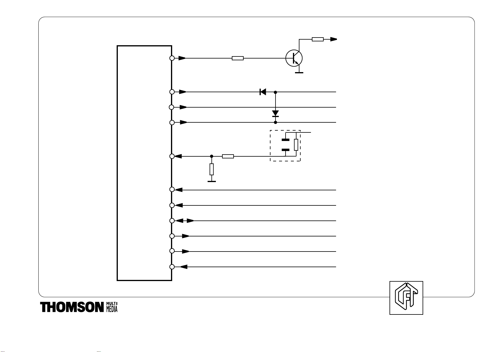
OTHER CONTROLS
The function of Pin 27 is to switch the power supply separately from the satellite
tuner.
Pin 40 is used to switch off the television set using a control independent of the
buses. This is very useful in the event of the buses being blocked.
The breathing line is pulled down via Transistor TR102. In addition, this line is
analysed by software to indicate whether the TV is a 100-Hz or 50-Hz model.
This is indicated by RR910 (RR910 = 10K, 4 V at 40 = 100 Hz; RR910 = 0,
0.6 V at 40 = 50 Hz).
Pin 41 has two functions:
• To control the ZOOM Module if the television set is so equipped.
• On the 28" SF and 32" 16/9 modules, it delivers a PWM (pulse width
modulation) signal to compensate for the earth's magnetic field.
Pin 42 informs and analogue-to-digital converter for the AFC (automatic
frequency control). It operates in Automatic Programming and Manual Search
Modes.
Pin 43 informs an analogue-to-digital converter. This is used to regulate the
contrast according to the ambient lighting.
Pins 44 and 45 receive slow switching from SCART sockets AV1 and AV2.
They are used to recognise the formats of received images: 4/3 and 16/9.
Pin 52 mutes the audio amplifiers. It is active at low level, and is present each
time the TV is switched on or off.
Pin 54 is reserved for the DOLBY SURROUND PROLOGIC function only, to
perform a software cut-off of the TV internal speakers, to free the central
channel. It does not act on the auxiliary external output sockets.
Pin 62 indicates the presence of fast switching from SCART socket AV1.
At Pin 28, the input when the microcontroller is initialised by its pull-up wiring
specifies the size of the read-only memory, IR002, by selecting the number of
pages to swap. It is completed by the wiring of Pins 63 and 61 to the 5VSBY.
NOTES
CENTRE DE
FORMATION TECHNIQUE
17
17
Table of contents


