Technicolor TC2450A User manual
Model:TC2450A
ENERGY
SAVING MODE


*SAFETY PRECAUTIONCAUTION
•••
WARNING:PLACEMENT INFORMATIONSAFETY INFORMATIONRATING PLATE LOCATIONFCC STATEMENTSWARNING:1CAUTION MARKING WAS LOCATED AT THE REAR OF THE APPARATUS.WARNING: TO REDUCE THE RISK OF ELECTRICSHOCK,DO NOT REMOVE COVER(OR BACK)NO USER SERVICEABLE PARTS INSIDE.REFER SERVICING TO QUALIFIED SERVICEPERSONNEL.The lightning flash with arrowhead symbol, within an equilateral triangle,is intended to alert the user to the presence of uninsulated“dangerous voltage”within the product's enclosure that may beof sufficient magnitude to constitute a risk of electric shock to persons.The exclamation point within an equilateral Triangle is intended to alert the user toThe presence of important operating andmaintenance (servicing) instructions in the literatureaccompanying the appliance.DANGER OF EXPLOSION IF BATTERY IS INCORRECTLY REPLACED. REPLACE ONLY WITH THE SAME OR EQUIVALENT TYPE. USE OF CONTROLS OR ADJUSTMENTS ORPERFORMANCE OF PROCEDURES OTHERTHAN THOSE SPECIFIED MAY RESULT INHAZARDOUS RADIATION EXPOSURE.
••
TO REDUCE THE RISK OF FIRE OR ELECTRICSHOCK, DO NOT EXPOSE THIS APPLIANCE TORAIN OR MOISTURE.TO REVENT FIRE OR SHOCK HAZARD, DO NOTEXPOSE THIS UNIT TO RAIN OR MOISTURE. DONOT PLACE OBJECTS FILLED WITH LIQUIDS ONOR NEAR THIS UNIT. SHOULD ANY TROUBLE OCCUR, DISCONNECTTHE AC POWER CORD AND REFER SERVICINGTO A QUALIFIED TECHNICIAN.Do not use this unit in places that are extremely hot, cold, dusty or humid. Do not restrict the airflow of this unit by placing itsomewhere with poor airflow, by covering it with a cloth, by placing it on bedding or carpeting. When connecting or disconnecting the AC power cord, grip the plug and not the cord itself. Pulling the cord may damage it and create a hazard. When you are not going to use the unit for a long period of time, disconnect the AC power cord. The rating plate is located on the rear of the unit.NOTE: This unit has been tested and found to comply with the limits for a Class B digital device, pursuantto Part 15 of the FCC Rules. These limits are designedto provide reasonable protection against harmful interference in a residential installation. This unit generates, uses and can radiate radiofrequency energy and, if not installed and used in accordance with the instructions, may cause harmful interference to radio communication. However, thereis no guarantee that interference will not occur in a particular installation. If this unit does cause harmful interference to radio or television reception, whichcan be determined by turning the unit off and on, the user is encouraged to try to correct the interference by one or more of the following measures: - Reorient or relocate the receiving antenna. - Increase the separation between the unit and receiver. -Connect the unit into an outlet on a circuit different from that to which the receiver is connected. - Consult the dealer or an experienced radio/TV technician for help.Changes or modifications to thisunit not expressly approved by the party responsible for compliance could void the user authorityto operate the unit.
••••
“HDMI, the HDMI logo and High-Definition Multimedia Interface are trademarks or registered trademarks of HDMI Licensing LLC.”

Energy saving mode
ACCESSORIES
Please check and identify the supplied accessories.
................................................................................................................
...........................................................................................................
GETTING S TARTED
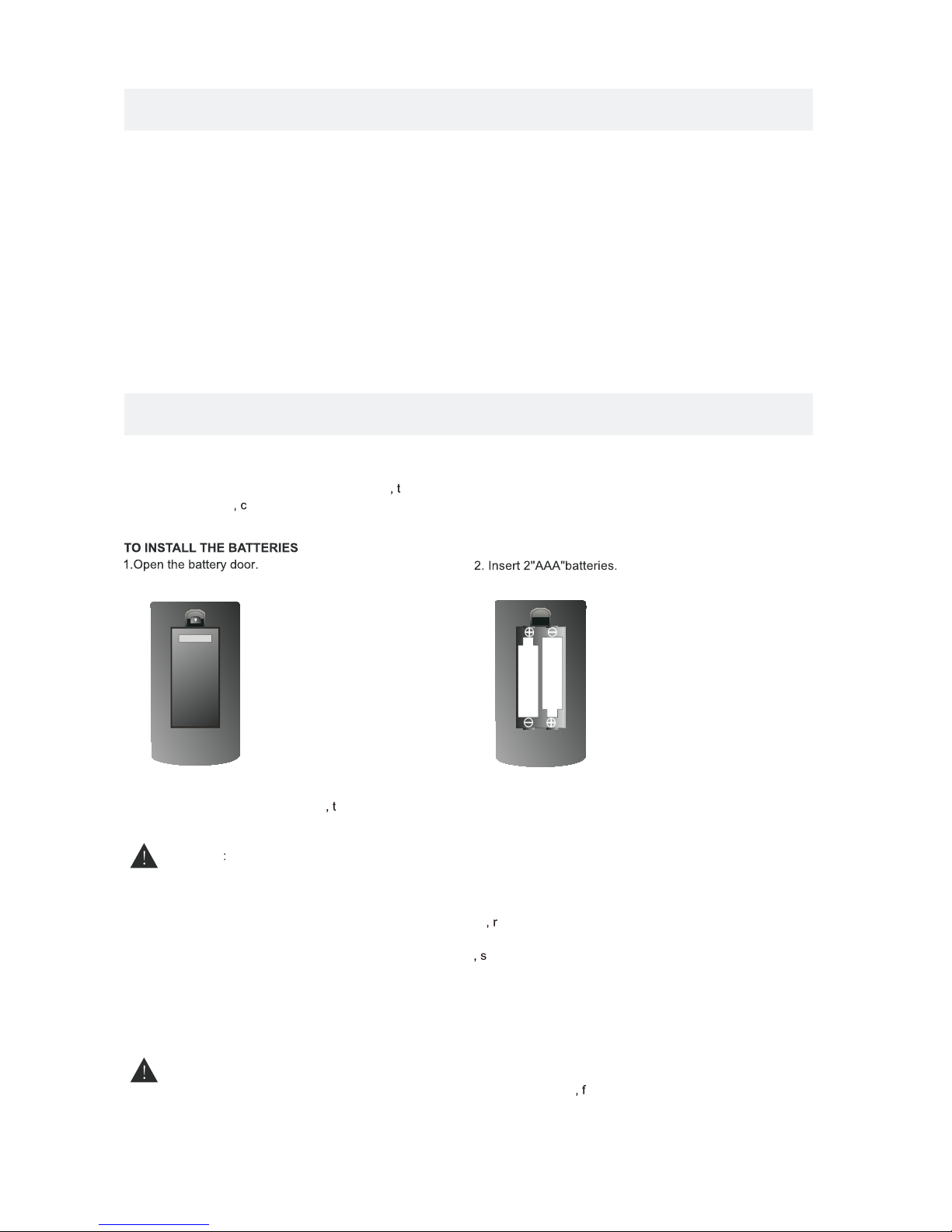
USINGTHEREMOTECONTROLBATTERY RE PL AC EME NTCAUTIONDanger of explosion if batter y is incorrectly replaced.
NOTES WAR NING :3
x 2
x 1
x 1
x 1
Remote control .................................................................................................................
Remote control
Battery(AAA)
Warranty Card
Instruction Manual
·Point the remote control at the remote sensor located on the unit.
·When there is a strong ambient light source he performance of the infrared remote sensor
·may be degraded ausing unreliable operation.
·The recommended effective distance for remote operation is about 16 feet (5 meters).
When the batteries become weak he operating distance of the remote control is greatly
reduced and you will need to replace the batteries.
·If the remote control is not going to be used for a long time emove the batteries to avoid
damage caused by battery leakage corrosion.
·Do not mix old and new batteries. Do not mix ALKALINE tandard (CARBON-ZINC) or
rechargeable (NICKEL-CADMIUM) batteries.
·Always remove batteries as soon as they become weak.
·Weak batteries can leak and severely damage the remote control.
Do not dispose batteries in a fire. Batteries may explode or leak.
Batteries shall not be exposed to excessive heat such as sunshine ire or the like.
2Base stands and 4 screwsbase stand
..........................................................................
x 1
...................................................................................................................
Power adaptor ...........................................................................................................................................x 1

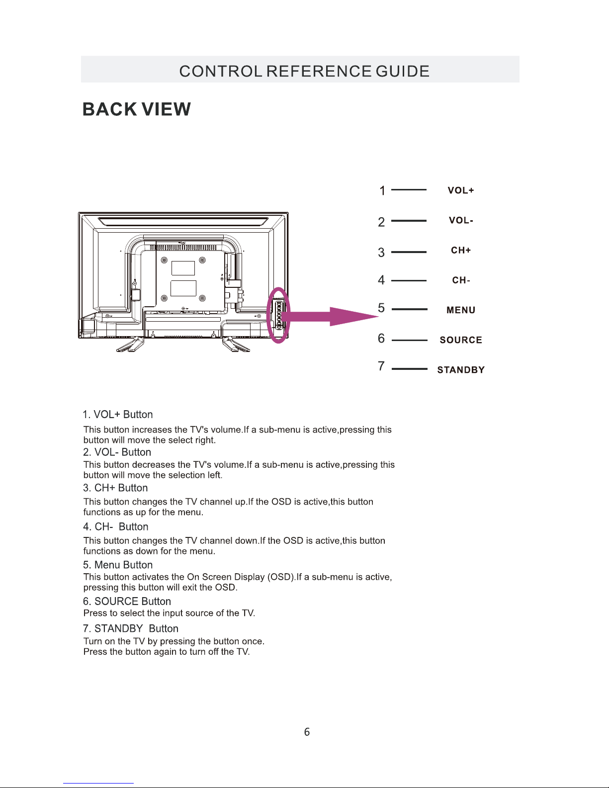
CONTROL REFERENCE GUIDE
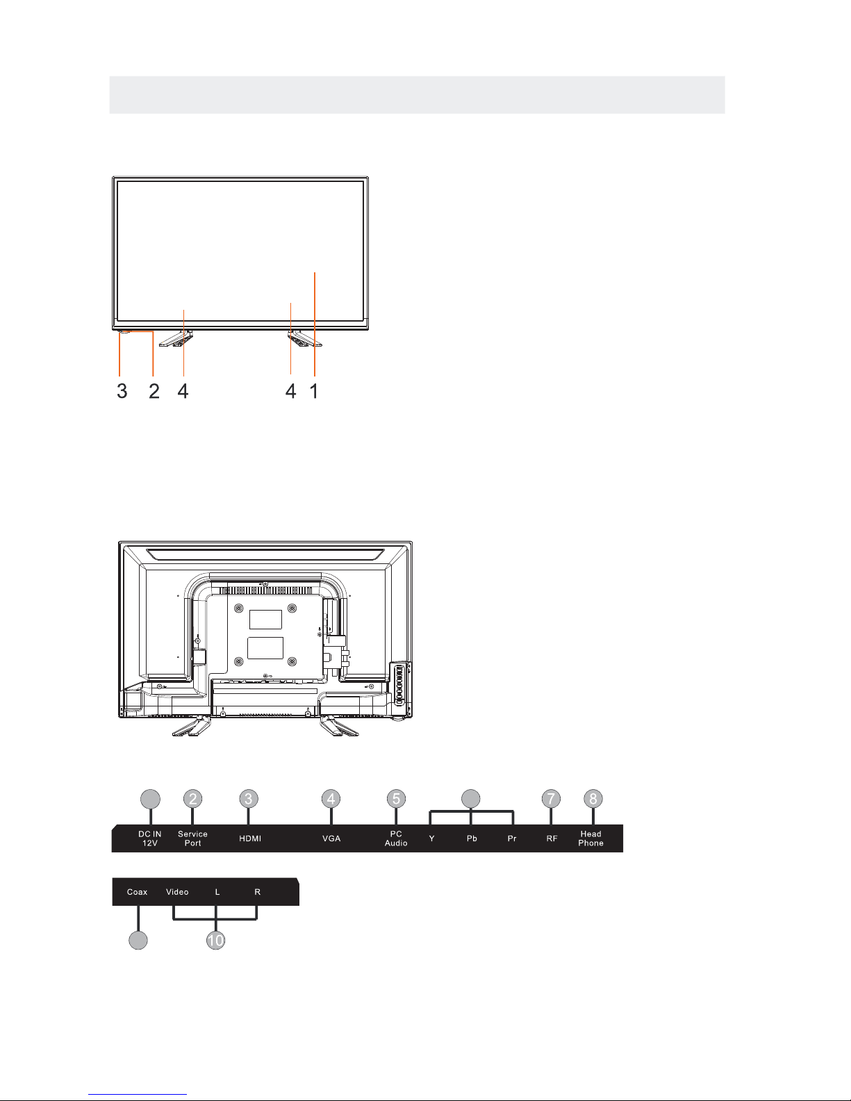
FRONT VIEW5BACK VIEW1.Color Screen2.Remote Sensor Do not block this sensor or theremote control will not work.3.Standby IndicatorIndicates whether the unit is ONor in STANDBY (OFF) mode.Lightin red: The unit is in STANDBY.Light in blue:The unit is turned ON.4.Speakers1.DC IN2.Service Port3.HDMI IN Jacks4.VGA IN Jack5.PC ADUIO IN Jack6.COMPONENT IN Jack7.TV ANTENNA Terminal8.Headphone Jack9.Coax OUT Jack10.AV IN Jack961
CONNECTIONS
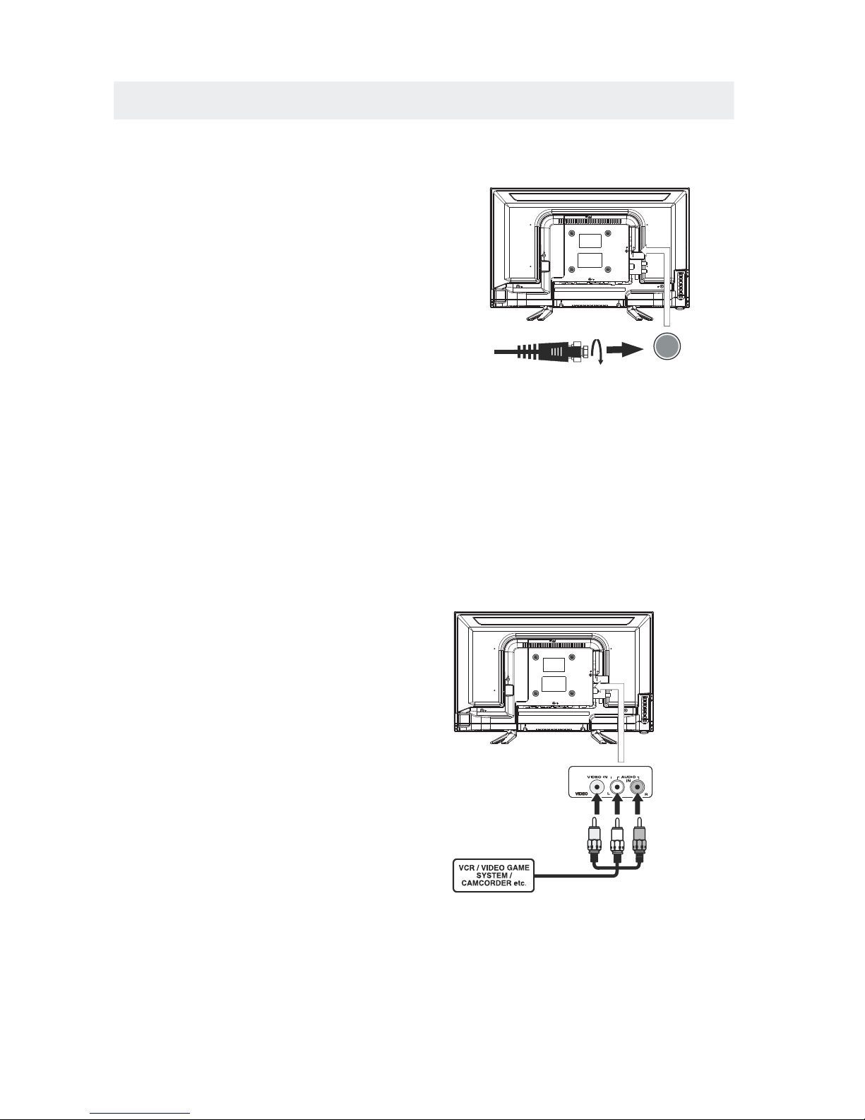
CONNECTING A TV ANTENNA / CABLE / SATELLITETo view television channels correctly, a signal mustbe received from one of the following sources:- An indoor or outdoor aerial antenna- A cable system- A satellite systemFor receiving over-the-air TV broadcasts, werecommend that you use an external fixed antenna.Should you require the use of a temporary antenna,please ensure that you purchase an antenna withsufficient ability to receive in weak signal areas.Only when you are in close proximity to a transmitterwill a temporary antenna reproduce a signal asstrongly as a fixed antenna.To connect to other equipment such as a VCR, camcorder, satellite system or cable, etc.CONNECTING AN A/V DEVICENOTECONNECTING DEVICES WITH A COMPOSITE VIDEO OUTPUTConnecting to a VCR / Video Game System / CamcorderAUDIOVIDEO OUTNOTETo connect A/V devices such as a VCR, video game system or camcorder.Connect the AUDIO / VIDEO cable (not included) as shown.Make sure you connect the cable from the other equipment (and) to this unit1P.lease refer to the user manual.for the other equipment formore information.Satellite, cable or TV antennacable to TV ANTENNAterminal (cable not included)7(AV in)2. Composite video input (shared with component)To AUDIO / VIDEOIN jacksTo AUDIO / VIDEOOUT jacksYELLOWWHITERED

CONNECTIONS
CONNECTING A HIGH-DEFINITION (HD) SOURCE USINGCONNECTIONNOTECOMPONENTHigh-Definition (HD) Devices with component video output must be connected to the Yinput.Connect the component video cable and audio cable (not included) as shown.Make sure you connect the component video cable and audio cable from the other equipmentWhen connecting a DVD player to the television,the picture resolution is solely dependent uponthe resolution supported by the DVD player attached.DVD player resolutions vary from 480i to 1080i.and this television can support DVD players up toa maximum resolution of 1080i.PbPr* May require a subscription
for receiving HD channels,check with your cable/satelliteservice provider for details.To COMPONENTVIDEO OUT jacks
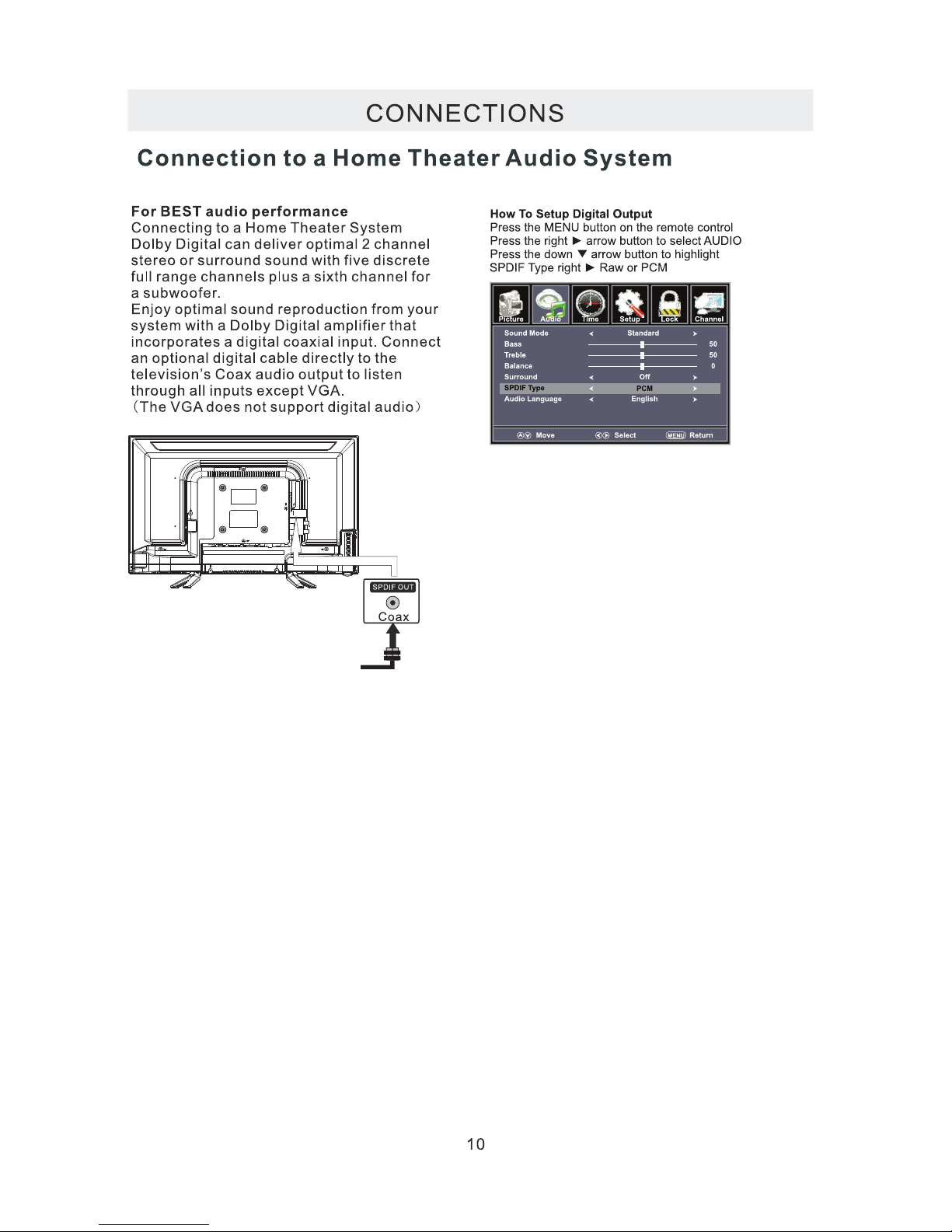
CONNECTING A HIGH-DEFINITION (HD) SOURCE USING HDMI CONNECTIONHDMI (High Definition Multimedia Interface) supports both video and audio on a single digital connectionfor use with DVD players, DTV, set-topboxes and other digital AV devices. HDMI was developed to providethe technologies of High Bandwidth Digital Content Protection (HDCP) as well as Digital Visual Interface(DVI) in one specification. HDCP is used to protect digital content transmitted and received byDVI-compliant or HDMIcompliant displays.HDMI has the capability to support standard, enhanced or high-definition video plus standard tomulti-channel surround-sound audio. HDMI features include uncompressed digital video, a bandwidth ofup to 2.2 gigabytes per second (with HDTV signals), one connector (instead of several cables andconnectors), and communication between the AV source and AV devices such as DTVs.
To HDMIIN jackTo HDMIjackOUTTo COMPONENTVIDEO IN jacksAUDIO IN jacksTo COMPONENT AUDIOOUT jacksConnect the HDMI cable (not included) asshown:Make sure you connect the cable from thesource equipment () to this unit().HDMI OUTHDMI INHDMI CABLE(NOT INCLUDED)(COMPONENT OUT and AUDIO OUT)to the unit COMPONENT IN.COMPONENT IN8To COMPONENT
CONNECTIONS
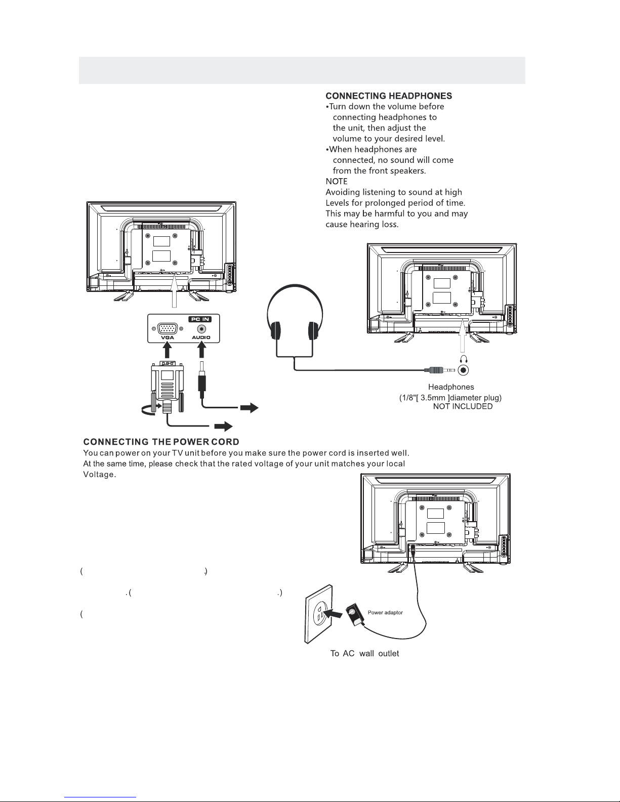
CONNECTING AAUDIO - PC OUTVGAAUDIO - PC INPCVGAConnect the 15-pin D-SUB PC/VGA connectorfrom your computer to the 15-pin D-SUB PC/VGAinput on this unit using a monitor cable and anaudio cable (not included) as shown.Make sure you connect the cable from the computer(and) to this unit(and).TO PC ConnectorTO AUDIO OUT jacks
NOTE•Insert the power plug fully into the socket outletIf the power plug is looseit could generate heat andcause fireDo not touch the power plug with a wet handThis may cause electrical shockDo not use any power cord other than that providedwith this TVThis may cause fire or electrical shockDo not damage the power cordA damaged cord may cause fire or electrical shock•Do not move the TV with the cord plugged in thesocket outlet.•Do not place a heavy object on the cord or placethe cord near a high-temperature object.•Do not twist the cord, bend it excessively, or stretch it.•Do not pull on the cord. Hold onto the power plug body when disconnecting cord.•Do not use a damaged power plug or socket outlet..(,.)..•••connected to prevent electrical shock.
Ensure that the power plug is easily accessible.Ensure the earth pin on the power plug is securely
••
9
.)
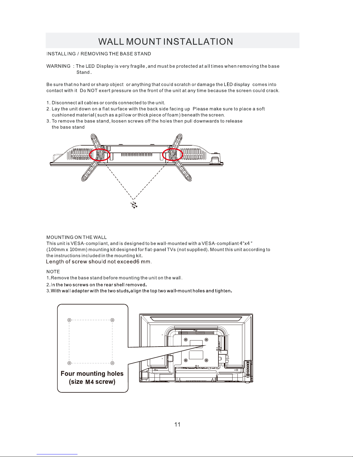
4”
4”
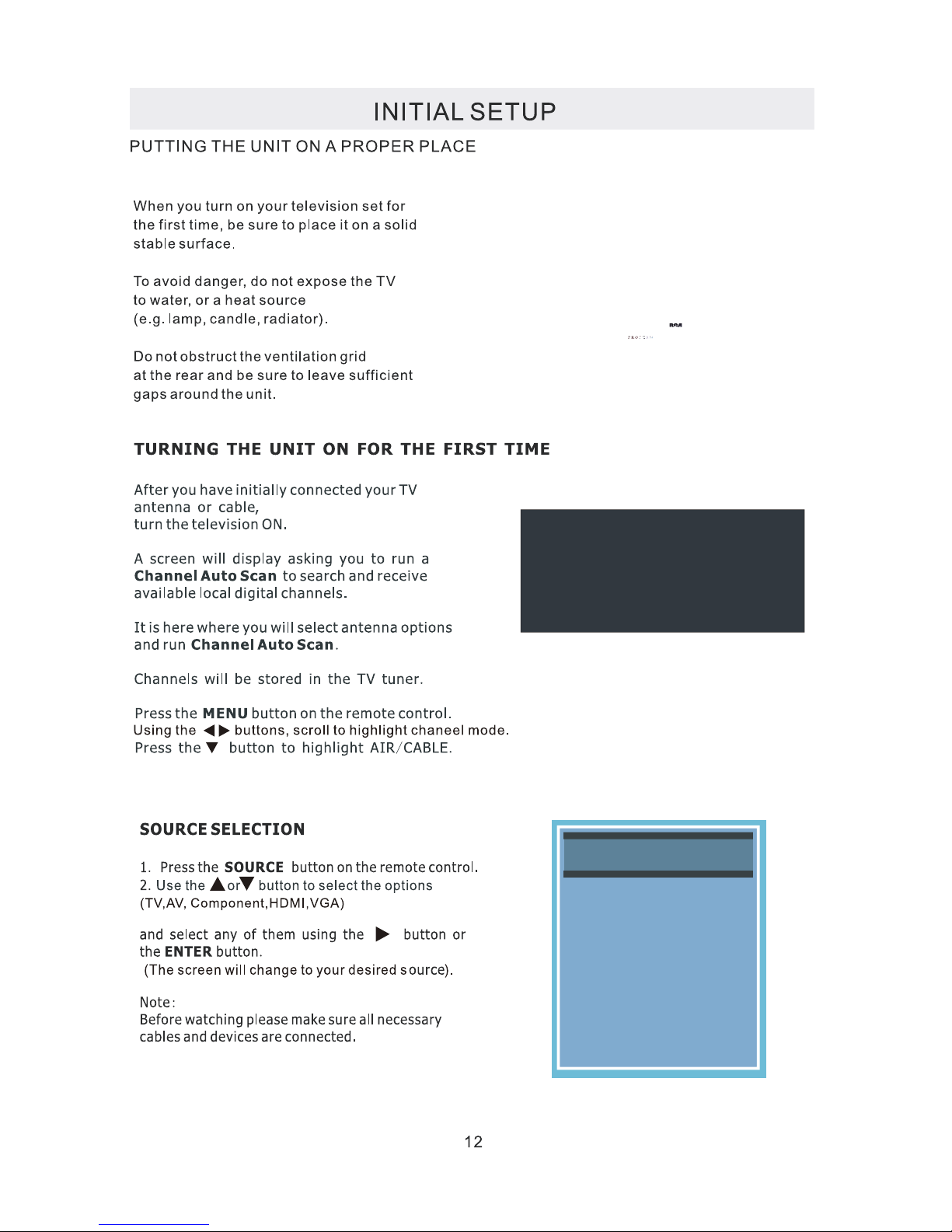
Please Run
Channel Auto Scan
INPUT SOURCE
TV
Component
HDMI
VGA
AV

Good Good

temp.

TV SETUP
15
TV SETUP
16
TV SETUP
17
Table of contents
Other Technicolor LED TV manuals


