manuals.online logo
Brands
  1. Home
  2. •
  3. Brands
  4. •
  5. Technics
  6. •
  7. CD Player
  8. •
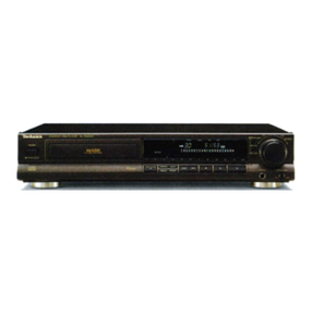
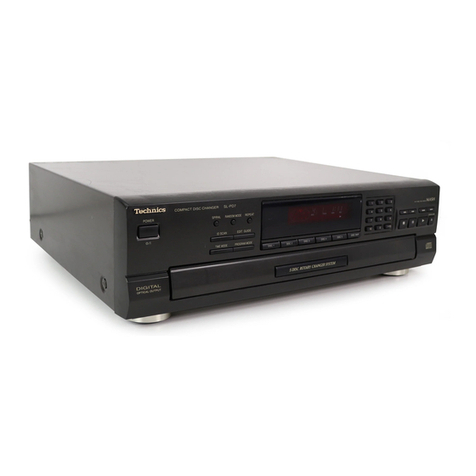
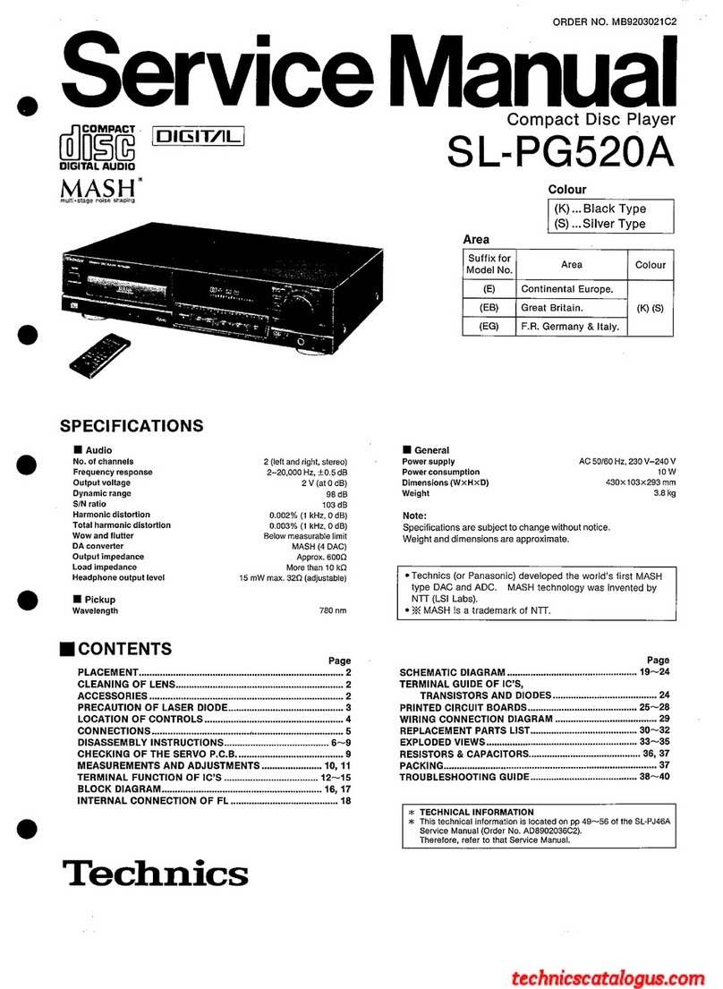
  9. Technics SL-PS670D User manual

Technics SL-PS670D User manual

Other Technics CD Player manuals

Technics SL-EH600 User manual

Technics

Technics SL-EH600 User manual

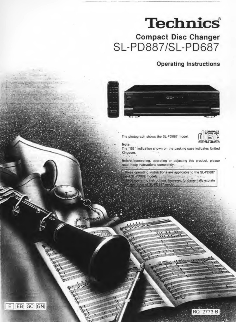
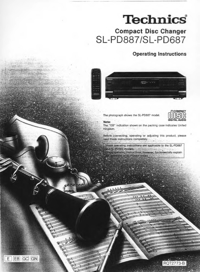
Technics sl-pd887 User manual

Technics

Technics sl-pd887 User manual

Technics SL-PS7 User manual

Technics

Technics SL-PS7 User manual

Technics SL-PC14 User manual

Technics

Technics SL-PC14 User manual

Technics SL-PD1348 User manual

Technics

Technics SL-PD1348 User manual

Technics SL-G700M2 Installation and service instructions

Technics

Technics SL-G700M2 Installation and service instructions

Technics SLMC7 - COMPACT DISC CHANGER User manual

Technics

Technics SLMC7 - COMPACT DISC CHANGER User manual

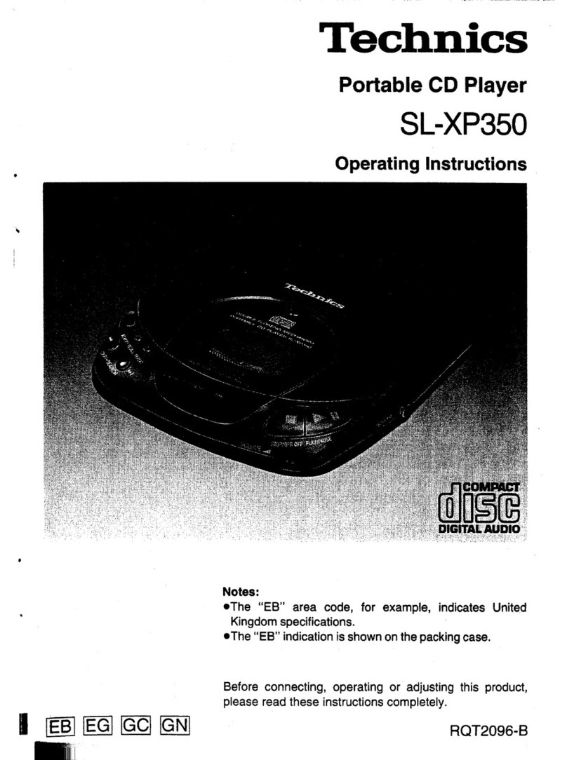
Technics SL-XP350 User manual

Technics

Technics SL-XP350 User manual

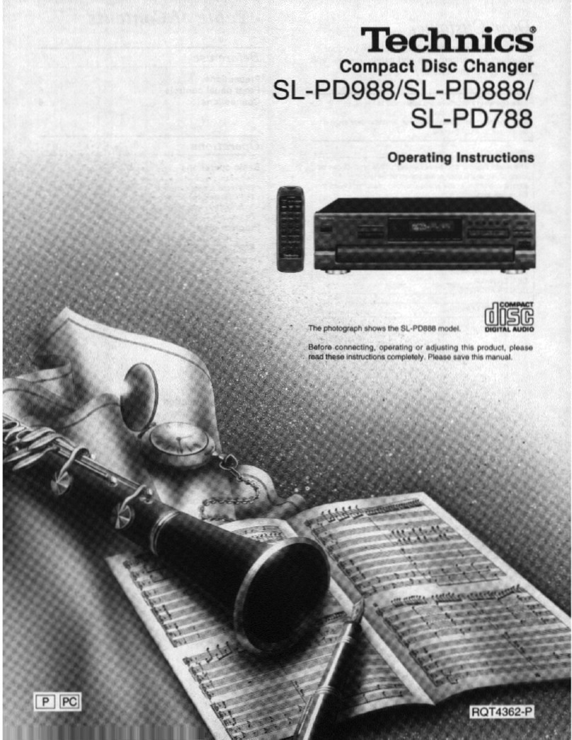
Technics SL-PD988 User manual

Technics

Technics SL-PD988 User manual

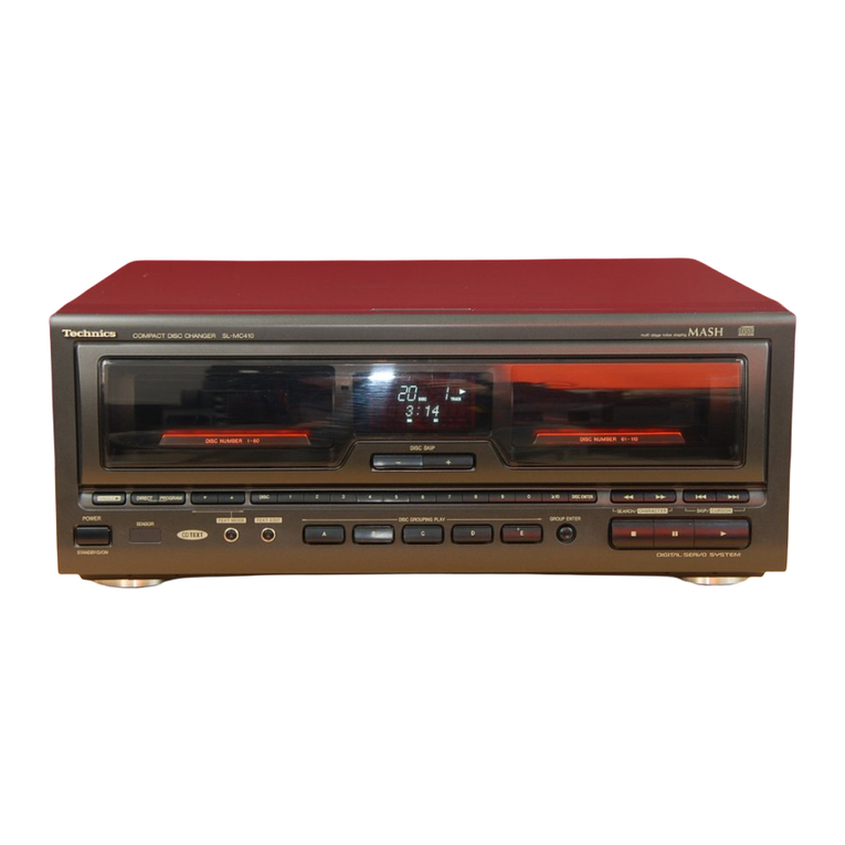
Technics sl-mc410 User manual

Technics

Technics sl-mc410 User manual

Technics SL-PG360A - service User manual

Technics

Technics SL-PG360A - service User manual

Technics SL-EH760 User manual

Technics

Technics SL-EH760 User manual

Technics SL-XP600 User manual

Technics

Technics SL-XP600 User manual

Technics SL-MC310 User manual

Technics

Technics SL-MC310 User manual

Technics SL-PS7 User manual

Technics

Technics SL-PS7 User manual

Technics SL-PG590 User manual

Technics

Technics SL-PG590 User manual

Technics SL-PG350 User manual

Technics

Technics SL-PG350 User manual

Technics SL-PD967 User manual

Technics

Technics SL-PD967 User manual

Technics SL-PS50 User manual

Technics

Technics SL-PS50 User manual

Technics SL-PD988 User manual

Technics

Technics SL-PD988 User manual

Technics SL-XP700 User manual

Technics

Technics SL-XP700 User manual

Technics SLPD6 - COMPACT DISC CHANGER User manual

Technics

Technics SLPD6 - COMPACT DISC CHANGER User manual

Technics SLPD8 - COMPACT DISC CHANGER User manual

Technics

Technics SLPD8 - COMPACT DISC CHANGER User manual

Technics SL-P1 User manual

Technics

Technics SL-P1 User manual

Popular CD Player manuals by other brands

Arcam CD23 Handbook

Arcam

Arcam CD23 Handbook

Sanyo MCD-Z1F Service manual

Sanyo

Sanyo MCD-Z1F Service manual

JVC RC-ST3SL instructions

JVC

JVC RC-ST3SL instructions

Marantz HD-CD1 quick start guide

Marantz

Marantz HD-CD1 quick start guide

Sony DVP-FX850 Service manual

Sony

Sony DVP-FX850 Service manual

Philips AZ1140 Instrukcja obs?ugi

Philips

Philips AZ1140 Instrukcja obs?ugi

Alpine 7909 owner's manual

Alpine

Alpine 7909 owner's manual

JVC CH-X350 instructions

JVC

JVC CH-X350 instructions

RCA RP-7923 instruction manual

RCA

RCA RP-7923 instruction manual

Pioneer DEH-P3550MP XM Operation manual

Pioneer

Pioneer DEH-P3550MP XM Operation manual

Philips Shockproof AX2102 brochure

Philips

Philips Shockproof AX2102 brochure

Philips CD582 user manual

Philips

Philips CD582 user manual

Philips AZ 6821 operating manual

Philips

Philips AZ 6821 operating manual

Lasonic MSU-2020 user manual

Lasonic

Lasonic MSU-2020 user manual

Denon DCD-1420 Service manual

Denon

Denon DCD-1420 Service manual

Panasonic SJ-MR100 operating instructions

Panasonic

Panasonic SJ-MR100 operating instructions

Onkyo DX-7210 instruction manual

Onkyo

Onkyo DX-7210 instruction manual

Cambridge Audio SONATA CD30 manual 

Cambridge Audio

Cambridge Audio SONATA CD30 manual 

manuals.online logo
manuals.online logoBrands
  • About & Mission
  • Contact us
  • Privacy Policy
  • Terms and Conditions

Copyright 2025 Manuals.Online. All Rights Reserved.

ORDER
NO.
MB9704076A2
Service
Manual
Compact
Disc
Player
=
Compact
Disc
Player
COMPACT
SL-PS670D
alise
DIGI
Colour
(K)...Black
Type
picitat
aupio
MA
AS
H*
Areas
multi-stage
noise
shaping
i
E
Sisie
wile
arab
8
Europe.
Please
file
and
use
this
manual
together
with
the
service
manual
for
Model
No.
SL-PS670A
(E,
EB,
EG),
Order
No.
MB9410050C2.
Note:
This
service
manual
is
provided
to
indicate
the
differences
between
the
original
model
No.
SL-PS670A
(E,
EB,
EG)
and
the
subsequent
model
No:
SL-PS670D
(E,
EB,
EG).
RAE1100Z
MECHANISM
SERIES
Specifications
im
Audio
i
General
No.
of
channels
2
(left
and
right,
stereo)
Power
consumption
,
14W
Frequency
response
2
-—
20,000
Hz,
+
0.5
dB
Power
supply
AC
50
Hz,
230
-—
240
V
Output
voltage
2
V
(at
0
dB)
Dimensions
(W
x
H
x
D)
430
x
114x290
mm
Dynamic
range
98
dB
Weight
4.0
kg
S/N
107
dB
Harmonic
distortion
0.002%
(1
kHz,
0
dB)
Note:
Total
harmonic
distortion
0.0027%
(1
kHz,
0
dB)
Specifications
are
subject
to
change
without
notice.
Wow
and
flutter
Below
measurable
limit
Weight
and
dimensions
are
approximate.
DA
converter
MASH
(1
bit)
Output
impedance
600
Q
For
United
Kingdom
only:
Load
impedance
More
than
10
k2
This
apparatus
was
produced
to
BS
800.
Headphone
output
level
15
mW
max.
32
Q
(adjustable)
@
Pickup
*
Wavelength
aan
@
MASH
is
a
trademark
of
NTT.
Laser
Power
No
hazardous
radiation
is
emitted
(with
safety
protection)
A
WARNING
This
service
information
is
designed
for
experienced
repair
technicians
only
and
is
not
designed
for
use
by
the
general
public.
It
does
not
contain
warnings
or
cautions
to
advise
non-technical
individuals
of
potential
dangers
in
attempting
to
service
a
product.
Products
powered
by
electricity
should
be
serviced
or
repaired
only
by
experienced
professional
technicians.
Any
attempt
to
service
or
repair
the
product
or
products
dealt
with
in
this
service
information
by
anyone
else
could
result
in
serious
injury
or
death.
Technics
©
1997
Matsushita
Electric
Industrial
Co.,
Ltd.
All
rights
reserved.
Unauthorized
copying
and
distribution
is
a
violation
of
law.
SL-PS670D
m
Schematic
Diagram
@
Power
Switch
/
Loading
Motor
/
Operation
/
Power
Supply
/
Headphones
Jack
/
Main
Circuit
(SL-PS670A
Service
Manual
of
pages
19
~
22.)
.
[4
main
circuit
[4
main
circuit
(ref.
pages19
~
20
of
SL-PS670A
service
manual.)
(ref.
pages19
~
20
of
SL-PS670A
service
manual.)
5
f
~ta02"~
a.3uH
|
Addition
ToLYSERVO
CIRCUIT
(CN702)
(page
17)
Zrrxe-THAmoower
z
C304 R308
6.3V100
47
DaovS
Deletion
[4
main
circuit
(i
main
circuit
(ref.
page
20
of
SL-PS670A
Service
Manual.)
(ref..
page
21
of
SL-PS670A
service
manual.)
Q31
2SD1862QSTV6
REGULATOR
Q33
2SC1740SQSTA
REGULATOR
Q34
2SA933SQRSTA
REGULATOR
Q32
2SB1240QSTV6
REGULATOR
|
SL-PS670D
Manual
of
pages
23
~
25.)
ice
lagramM
(SL-PS670A
Serv
t
Board
D
(ref.
pages
23
~
24
of
SL-PS670A
service
manual.)
ircui
@
Printed
C
Addition
wen
Deletion.
Addition
—
Addition—
Sa
Speen
at
vo
(REP2496A_M)
DIGITAL
(OPTICAL
OUT)
|
SL-PS670D
|
Wi
Change
in
Replacement
Parts
List
(SL-PS670A
Service
Manual
of
pages
34
~
37
and
41.)
Notes:
©
Mentioned
in
this
parts
list
is
only
those
different
from
Mode!
No.
SL-PS670A
(E,
EB.
EG).
Alt
other
parts
are
the
same
as
for
SL-PS670A
(E,
EB,
EG).
e
(Mj
indicates
in
Remarks
columns
parts
that
are
supplied
by
MESA.
@
(M8)
indicates
in
Remarks
columns
parts
that
are
supplied
by
MBV.
Part
Name
&
Description
Part
Number
SLPS670A
(E,
EB,
EG)
SL-PS6700
(E,
EB,
EG)
NIEGRATED
CIRCUIT
(S)
yiceot
|
BAAS60FE1
NJM4580EDTEt
ee
ene
a
TRANSFORMER
(S)
fn
RTP1K4B020
POWER
TRANSFORMER
A
(MBI
K
—
a
nL
oo
Sr
CAPACITORS
sere
[ore
CABINET
PARTS
le
RYP0546Z-K
raveors7ek
|
ERONT
PANEL
ASSY
piel
jer
|
AGU11458-K
rrouiasax
|
MAIN
BUTTON
eee
AGU1146B-K
RGU1146A-K
SUB
BUTTON
pier
[e£6)
(He
|
RLOZN3R3KL-D
RTPt
K4B020A
[ee
RGRO164B-B
RFKHLPS670DA
REAR
PANEL
ASS'Y
ls
AFKHLPS670AB
RFKHLPS670DB
——
.
nee
SL-PS670D
Ref.
No.
Part
Name
&
Description
Remarks
SL-PS670A
(E,
EB,
EG)=§SL-PS670D
(E,
EB,
EG)
LOADING
UNIT
PARTS
RAE1100Z-1
RAE1100Z-2
TRAVERSE
UNIT
|
[MB]
RMLO178-1
RML0352
LOCK
LEVER
[MB]
ACCESSORIES
=e
|
ROT3856-D
|
|
ROT3856-D
|
=o
[MB]
<ID>
RQT2665-D
INSTRUCITON
MANUAL
(EG)
[MB]
<IE>
=
SJP2276
SJP2249-3
STEREO
CONNECTION
CABLE
RQA0013
RQA0117
WARRANTY
CARD
Pim
|
=
MATERIALS
RPG2276
RPG3389
PACKING
CASE
ime)
Note:
The
“<IA>,
<IB>,
<IC>, <ID>,
<IE>"
marks
in
Remarks
indicate
language
of
instruction
manual.
RQT3857-E
RFKSLPS770AE
<lA>:
English,
Spanish,
Swedish,
Russian
<ID>:
German,
Italy,
French
<IB>:
Polish,
Czech
<IE>:
Dutch,
Danish
<IC>:
English
Printed
in
Germany
K9704YH/MK/TF
Compact
Disc
Player
tise
pieimaL
AUDIO
AA
AAS
HH
*
multi-stage
nolse
shaping
RAE1100Z
MECHANISM
SERIES
Specifications
B
Audio
No.
of
channels
Frequency
response
2
(left
and
right,
stereo)
2
—
20,000
Hz,
+
0.5
dB
Output
voltage
2
V
(at
0
dB)
Dynamic
range
98
dB
S/N
107
dB
0.002%
(1
kHz,
0
dB)
0.0027%
(1
KHz,
0
dB)
Harmonic
distortion
Total
harmonic
distortion
Wow
and
flutter
-
Below
measurable
limit
DA
converter
MASH
(1
bit)
Output
impedance
600
2
Load
impedance
More
than
10
kQ
Headphone
output
level
15
mW
max.
32
Q
(adjustable)
@
Pickup
Wavelength
780
nm
Laser
Power
No
hazardous
radiation
is
emitted
(with
safety
protection)
ORDER
NO.
MB9410050C2
Service
Manual
Compact
Disc
Player
SL-PS670A
Colour
Areas
Model
No.
elem
|
m@
General
Power
consumption
15
W
Power
supply
AC
50/60
Hz,
230
~
240
V
Dimensions
(W
x
Hx
D)
430
x
114x290
mm
Weight
4.0
kg
Note:
Specifications
are
subject
to
change
without
notice.
Weight
and
dimensions
are
approximate.
For
United
Kingdom
only:
This
apparatus
was
produced
to
BS
800.
*
@
MASH
is
a
trademark
of
NTT.
Z\AWARNING
This
service
information
is
designed
for
experienced
repair
technicians
only
and
is
designed
for
use
by
the
general
public.
It
does
not
contain
warnings
or
cautions
to
advise
non-technical
individuals
of
potential
dangers
in
attempting
to
service
a
product.
Products
powered
by
electricity
should
be
serviced
or
repaired
only
by
experienced
professional
technicians.
Any
attempt
to
service
or
repair
the
product
or
products
dealt
with
in
this
service
information
by
anyone
else
could
result
in
serious
injury
or
death.
Technics
©
1994
Matsushita
Electric
Industrial
Co.,
Ltd.
All
rights
reserved.
Unauthorized
copying
and
distribution
is
a
violation
of
law.
SL-PS670A
m@
Contents
®
Handling
Precautions
for
Traverse
DeCK
....ccc
ccc
eeeesereereeeenes
2
@
Precaution
of
Laser
Diode....
2,3
©
ACCOSSOMIOCS
sscevscicissscvsnsveesvevecstcecestusvecetaceasgustusntecsoovseoanstdeccevavedieseases
3
@
CONNECTIONS
00...
eee
seette
tees
ed
@
Caution
for
AC
Mains
Lead...
4
@
Location
of
Controls..............
«5
@
Basic
Operating
Procedure
oo...
.ccccssssseecessesseseseesescseereseeseresseee
6
®@
Operation
Check
and
Main
Component
Replacement
Procedures
........
cscs
7~13
@
BlOCK
Diagram
sisciccsccsvescccssesesscssecsseveedsensessenscorecesessegceneatensavaseeas
14,15
Page
@
Schematic
Diagram
s.isecccscsies
i
pesedaceseeseucunteceesnarecsersnevarees
cette
16~22
@
Printed
Circuit
Board
Diagram
oo...
cess
eseteerensereseees
23~25
@
Wiring
Cornnection
Diagram
wo.
.cceccsssssseeescssereecescseeesssnsseeseerenies
26
@
Troubleshooting
Guide
me
@
Automatic
Adjustment
Results
Display
Function
0...
29
@
Function
of
IC
Terminals
.......
ccc
cscecseeecsserssessseseenssssesesseseees
30~33
@
Replacement
Parts
List
.........
cs
essssessessereerseeesseeteesseaseessasees
34~41
®@
Cabinet
Paris
Location
....
..
38,39
@
Loadiong
Unit
Parts
Location
0.0...
cccsetessssseeessecseesstenseersseries
40
@
Handing
Precautions
for
Traverse
Deck
The
laser
diode
in
the
traverse
deck
(optical
pickup)
may
break
down
due
to
potential
difference
caused
by
static
electricity
of
clothes
or
human
body.
So,
be
careful
of
electrostatic
breakdown
during
repair
of
the
traverse
deck
(optical
pickup).
@
Handling
of
traverse
deck
(optical
pickup)
1.
Do
not
subject
the
traverse
deck
(optical
pickup)
to
static
electricity
as
it
is
extremely
sensitive
to
electrical
shock.
2.
To
prevent
the
breakdown
of
the
laser
diode,
an
anti-static
shorting
pin
is
inserted
into
the
flexible
board
(FPC
board).
When
removing
or
connecting
the
short
pin,
finish
the
job
in
as
short
time
as
possible.
3.
Take
care
not
to
apply
excessive
stress
to
the
flexible
board
(FPC
board).
4.
Do
not
turn
the
variable
resistor
(laser
power
adjustment).
It
has
al-
ready
been
adjusted.
®
Grounding
for
electrostatic
breakdown
prevention
1.
Human
body
grounding
Use
the
anti-static
wrist
strap
to
discharge
the
static
electricity
from
your
body.
2.
Work
table
grounding
Put
a
conducive
material
(sheet)
or
steel
sheet
on
the
area
where
the
traverse
deck
(optical
pickup)
is
placed,
and
ground
the
sheet.
Caution:
The
static
electricity
of
your
clothes
will
not
be
grounded
through
the
wrist
strap.
So,
take
care
not
to
let
your
clothes
touch
the
traverse
deck
(optical
pickup).
m@
Precaution
of
Laser
Diode
CAUTION:
Wave
length:
780
nm
FPC
po
Lens
(Do
not
touch)
;
(Handle
it
carefully)
Be
sure
to
short
this
portion
(Use
the
shorting
pin
or
clip)
Iron
plate
or
some
metals
to
conduct
electricity
This
product
utilizes
a
laser
diode
with
the
unit
turned
“on”,
invisible
laser
radiation
is
emitted
from
the
pick
up
lens.
Maximum
output
radiation
power
from
pick
up:
100
uW/VDE
Laser
radiation
from
the
pick
up
unit
is
safety
level,
but
be
sure
the
followings:
1.
Do
not
disassemble
the
pick
up
unit,
since
radiation
from
exposed
laser
diode
is
dangerous.
2.
Do
not
adjust
the
variable
resistor
on
the
pick
up
unit.
It
was
already
adjusted.
3.
Do
not
lock
at
the
focus
lens
using
optical
instruments.
4.
Recommend
not
to
lock
at
pick
up
lens
for
a
long
time.
ACHTUNG:
abgestrahlt.
Wellenlange:
780
nm
Dieses
Produkt
enthalt
eine
Laserdiode.
Im
eingeschalteten
Zustand
wird
unsichtbare
Laserstrahlung
von
der
Lasereinheit
Maximale
Strahlungsleistung
der
Lasereinheit:
100WW/VDE
Die
Strahlung
an
der
Lasereinheit
ist
ungefahrlich,
wenn
folgende
Punkte
beachtet
werden:
1.
Die
Lasereinheit
nicht
zerlegen,
da
die
Strahlung
an
der
freigelegten
Laserdiode
gefahrlich
ist.
2.
Den
werksseitig
justierten
Einstellregler
der
Lasereinheit
nicht
verstellen.
3.
Nicht
mit
optischen
Instrumenten
in
die
Fokussierlinse
blicken.
4,
Nicht
Uber
langere
Zeit
in
die
Fokussierlinse
blicken.
LUOKAN
1
LASERLAITE
KLASS
1
LASER
APPARAT
SL-PS670A
CLASS
1
LASER
PRODUCT
DANGER
INVISIBLE
LASER
RADIATION
WHEN
OPEN.
AVOID
DIRECT
EXPOSURE
TO
BEAM.
ADVARSEL
USYWLG
LASERSTRILING
vEp
AawnG,
WR
SaxERHEDSAFBRYDERE
ER
UDE
AF
FUNKTION.
UHOGK
UOSTIELSE
FOR
STRILING.
VARO!
_AVATTAESSA
JA
SUOJALUKITUS
OHITETTAESSA
OLET
ALTTNA
WAKYMATON
LASERSATERYLLE,
ALA
KATSO
SATEESEN,
VARNING
OSYMLIG
LASERSTAALNING
NAR
DENNA
DEL
AR
OPPHAD
OCH
SPRAREN
AA
URKOPPLAD.
BETRAKTA
EJ
STRALEN,
USYNLIG
LASERSTRILING
NA
DEKSEL
KPNES
1G
SIKKERHEDS
ADVERSEL
partis.
_uanGh
EXSPONAING
Fon
STRILEN,
VORSICHT
UNSICHTBARE
LASERSTRAHLUNG,
WENN
ABDECKUNG
GEDFFRET.
WICHT
DEM
STRAHL
AUSSETZEN,
ROLSOW!
m
Accessories
FREMOLSSCONMMON!
ccc,
ces
iveesteies
sd
sues
deteeenteel
thee
sanseved
eaves
eeu
tbs
bas
vbw
1
pe.
(EUR642101)
Stereo
CONMECHION
CADIO......cecccesssesesesescsescsssesssssssessessccstscasscseas
1
pe.
Battery
for
remote
CONHIO!
........ccccsccssescesessessssescessesasssesesessessersavace
2
pcs.
(SJP2276}
(UM-4,
AAA,
R03)
Bolore
making
connections,
be
sure
that
the
power
of
this
unit
and
all
other
system
compononts
is
first
turned
off.
Soe
tho
operating
Instructions
of
{he
amplilier
or
the
cassette
deck
for
details.
The
configuration
of
the
AC
outlet
and
AC
mains
lead
differ
accord-
ing
to
the
area.
Amplifier
(not
included)
FOR
UNITED
KINGDOM
ONLY
BE
SURE
TO
READ
THE
CAUTION
FOR
AC
MAINS
LEAD
ON
PAGE
4
BEFORE
CONNECTING
THE
AC
MAINS
LEAD.
Household
mains
outlet
ar)
lf
your
amplifier
has
the
AC
outlet,
you
can
also
connect
the
AC
mains
lead
to
the
“AC
OUTLET”
of
the
amplifier.
DIGITAL
Remove
a
dust-protection
cap
which
is
inserted
in
DIGITAL
OPTICAL
OUT
terminal
only
when
you
connect
to
the
digital
amplifier.
When
this
terminal
is
not
being
used,
attach
the
cap
as
shown
in
the
illustration
above.
SL-PS670A
mCaution
for
AC
Mains
Lead
(For
United
Kingdom)
(“EB”
area
code
model
only)
For
your
safety,
please
read
the
following
text
care-
frilly
runny.
This
appliance
is
supplied
with
a
moulded
three
pin
mains
plug
for
your
safety
and
convenience.
A
5-ampere
fuse
is
fitted
in
this
plug.
:
Should
the
fuse
need
to
be
replaced
please
ensure
that
the
replacement
fuse
has
a
rating
of
5-ampere
and
that
itis
approved
by
ASTA
or
BS!
to
BS1362.
Check
for
the
ASTA
mark
@>
or
the
BSI
mark
Y
on
the
body
of
the
fuse.
If
the
plug
contains
a
removable
fuse
cover
you
must
ensure
that
it
is
refitted
when
the
fuse
is
replaced.
If
you
lose
the
fuse
cover
the
plug
must
not
be
used
until
a
replacement
cover
is
obtained.
A
replacement
fuse
cover
can
be
purchased
from
your
local
dealer.
CAUTION!
IF
THE
FITTED
MOULDED
PLUG
IS
UNSUIT-
ABLE
FOR
THE
SOCKET
OUTLET
IN
YOUR
HOME
THEN
THE
FUSE
SHOULD
BE
RE-
MOVED
AND
THE
PLUG
CUT
OFF
AND
DIS-
POSED
OF
SAFELY.
THERE
IS
A
DANGER
OF
SEVERE
ELECTRI-
CAL
SHOCK
IF
THE
CUT
OFF
PLUG
IS
IN-
SERTED
INTO
ANY
13-AMPERE
SOCKET.
If
a
new
plug
is
to
be
fitted
please
observe
the
wiring
code
as
shown
below.
If
in
any
doubt
please
consult
a
qualified
electrician.
IMPORTANT
If
the
socket
outlets
in
the
home
are
not
suitable
for
the
plug
supplied
with
this
appliance
it
should
be
cut
off
and
an
appropriate
three
pin
plug
fitted.
The
wires
in
this
mains
lead
are
coloured
in
accor-
dance
with
the
following
code:
Blue:
Neutral
Brown:
Live
Do
not
connect
either
wire
to
the
earth
terminal
in
the
plug
which
is
marked
by
the
letter
“E”
or
by
the
safety
earth
symbol
—
or
coloured
green
or
green-and-
yellow.
As
the
colours
of
the
wires
in
the
mains
lead
of
this
apparatus
may
not
correspond
with
the
coloured
mark-
ings
identifying
the
terminals
in
your
plug
proceed
as
follows.
The
wire
which
is
coloured
BLUE
must
be
con-
nected
to
the
terminal
which
is
marked
with
the
letter
N
or
coloured
BLACK.
The
wire
which
is
coloured
BROWN
must
be
con-
nected
to
the
terminal
which
is
marked
with
the
letter
L
or
coloured
RED.
Before
use
Remove
the
connector
cover
as
follows.
Connector
How
to
replace
the
fuse
1.
Open
the
fuse
cover
with
a
screwdriver.
eoneense
ae?
'
Fuse
(5
ampere)
m@
Location
of
Controls
Tee
Tue
LENGTH
DEAT
FADE
No.
Name
@)
Power
“STANDBY
(/ON”
switch
(POWER,
STANDBY
(5/ON)
Press
to
switch
the
unit
from
on
to
standby
mode
or
vice
versa.
In
standby
mode,
the
unit
is
still
consuming
a
small
amount
of
power.
@
Standby
indicator
(STANDBY)
When
the
unit
is
connected
to
the
AC
mains
suppiy,
this
indica-
tor
lights
up
in
standby
mode
and
goes
out
when
the
unit
is
turned
on.
@
Peak
search
button
(PEAK
SEARCH)
©)
Auto
cue
button
(AUTO
CUE)
©
Disc
tray
@)
Disc
tray
open/close
button
(4
OPEN/CLOSE)
Numeric
buttons
(1—9,
0,
210)
@)
Random
play
button
(RANDOM)
Repeat
button
(REPEAT)
4)
Remote
control
signal
sensor
(SENSOR)
42
Headphones
jack
(PHONES)
(¢
6.3,
32
Q)
@3)
Headphones
volume
level
knob
(PHONES
LEVEL)
SL-PS670A
No.
Name
CD
edit
record
buttons
(EDIT
GUIDE)
Tape
length
button
(TAPE
LENGTH)
eTape
side
select
button
(SIDE
A/B)
®Time
fade
button
(TIME
FADE)
@5
Display
panel
Search
buttons
(<<,
>>)
@D
Skip
buttons
(<4,
>P!)
Program
play
buttons
eProgram
button
(PROGRAM)
Clear
button
(CLEAR)
Recall
button
(RECALL)
Stop
button
(Ml)
@0)
Pause
button
(EI)
@2)
Play
button
(>)