Technische Alternative UVR61-3 Wiring diagram
1
Supplementary instructions for UVR61-3
Building drying with ventilator
A special application of the universal controller is the energy-saving and cost-effective drying of
basements and other building parts with fan control. The special functionality (measurement of the
absolute humidity) of the sensor RFS-DL enables this simple drying out of buildings in connection with
the universal controller. The absolute humidity inside and outside is compared and a fan switched on
or off accordingly.
Building drying can be carried out with all universal controllers that have a DL bus (with the excep-
tion of UVR63-H).
Goal
Lowering humidity through specific ventilation with dry air
Improvement of air quality and odour with regular ventilation
Replacement of energy-intensive dehumidification devices
Required material:
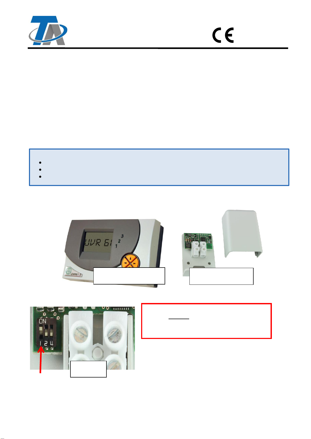
Complete UVR61-GT set comprising:
1 universal controller
01/UVR61-3-R
2 humidity sensors
01/RFS-DL
RFS-DL
for outside
The address must be changed if the RFS-DL is
installed outside.
The DIP switch 1 must be set to ON.
This changes the sensor address to 2.
UVR61-GT
Vers. 1.6 EN
Technische Alternative RT GmbH
A-3872 Amaliendorf, Langestr. 124

2
Planning principles
Blow direction of the fan always from the outside to the inside!
If the fan blows from the inside to the outside, there is a danger of warm and thus humid air
following from adjacent building parts thus increasing the problem!
A supply air fan is usually sufficient!
The “exhaust air” is pushed out through leaks in the building. With building that are very leak-
proof, an overflow opening (flap, …) must be created. If supply and exhaust fans are used, the
efficiency of the exhaust fan must never be above that of the supply fan.
The ventilated buildings (the ventilated room) must be as leak-proof as possible!
In order to prevent unwanted penetration of humid air through natural circulation, windows and
doors should be closed.
In order to (especially in the winter) keep the cooling of rooms within limits, timer-controlled
interval operation is useful. An additional minimum temperature monitoring can be imple-
mented.
The exterior humidity sensor must not be directly subjected to insolation or rain. If neces-
sary, the sensor will be protected with a small shield.
Operation
The large display contains the symbols for all important information and a plain text area. Naviga-
tion with the coordinate keys is matched to the display sequence.
Navigation keys for selecting the display and for changing parameters.
Entry to a menu, release of a value for changing with the navigation keys (enter key).
Return from the menu level selected last, exit from the parameterising of a value (return
key).
The side keys are the navigation keys for selecting the required display such as e.g. collector
or tank temperature during regular operation. A different sensor symbol and the corresponding tem-
perature are displayed for each pressure.
The appropriate symbol is displayed for information above the text line (according to the example
of the collector temperature). The choice of symbol has no effect on the control function. All instruc-
tion during parameterisation are below the text line.
To the side of the display, the currently active outputs are identifiable on the
green illuminated figures 1–3.
3
2
1
3
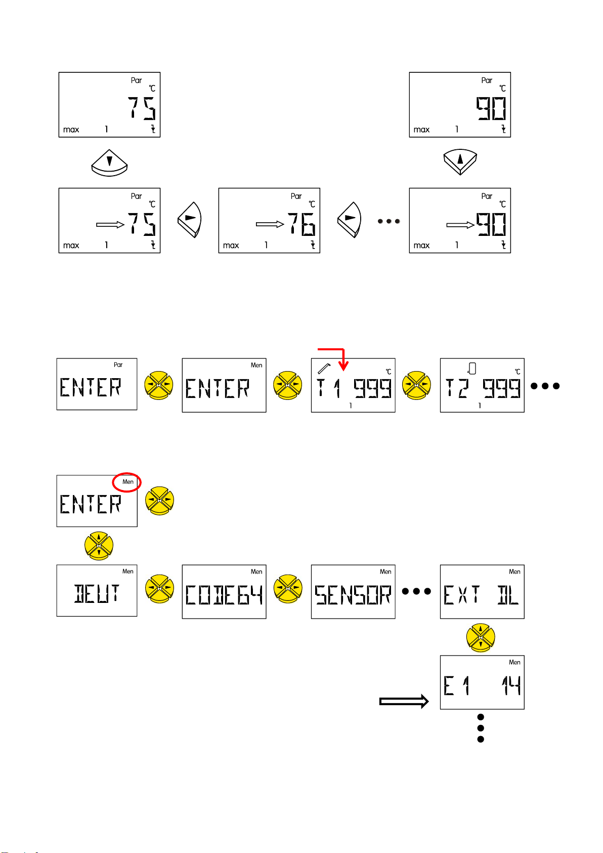
Changing a value (parameter)
If a value is to be changed, the arrow key in downward direction must be pressed. This value now
blinks and can be changed to the required value using the navigation keys.
The value is saved pressing the arrow key in upward direction.
View of the display after the first start of controller UVR61-3
Display after switching on
The sensor values initially show 999°C because no sensors are defined as yet.
Access to menu ENTER/Men and setting of external sensors
Sample setting for the
applications 1-4
Value
blinks
Value
blinks
Value
blinks
4
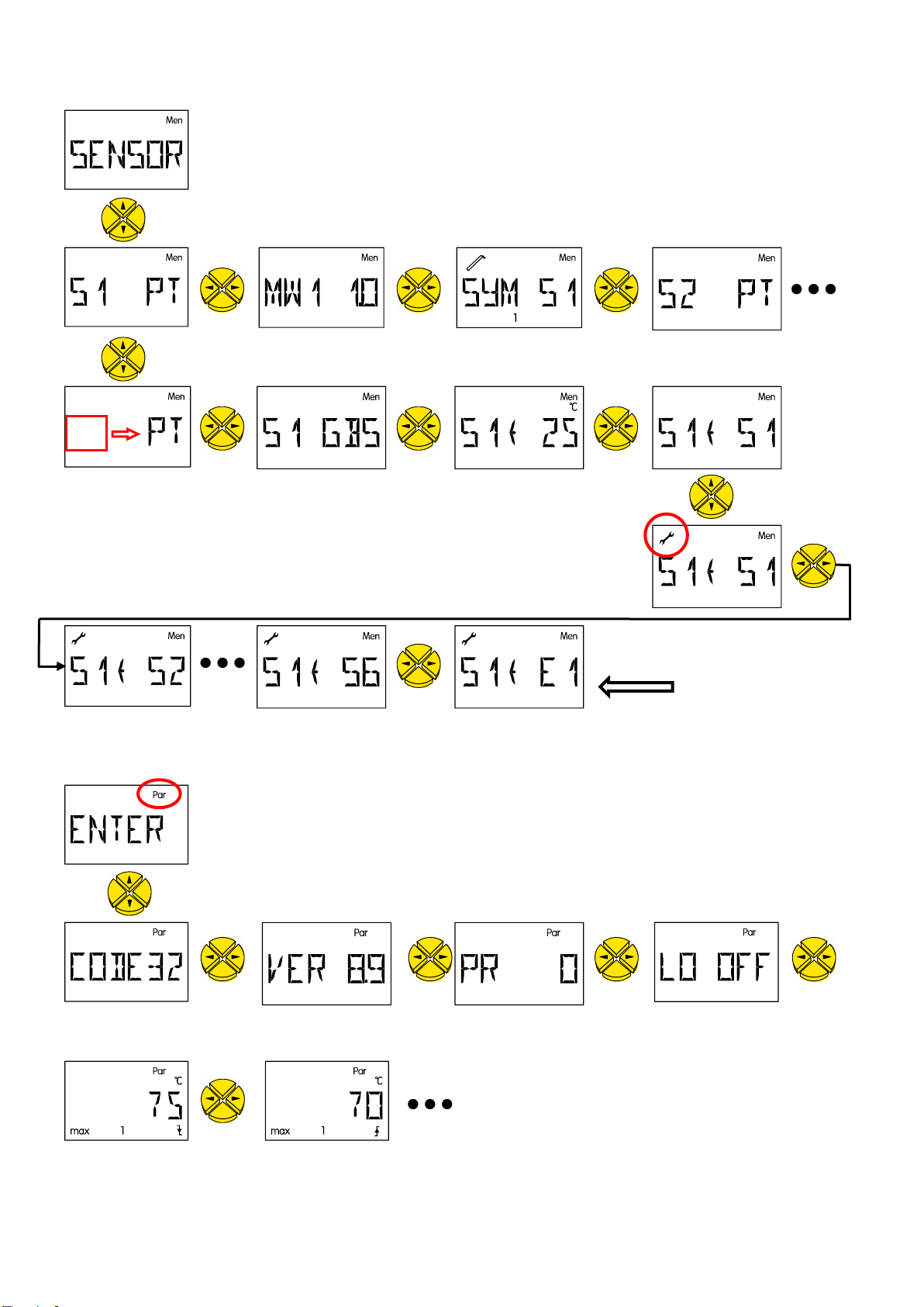
Allocation of the external sensors to sensor values in the menu SENSOR
Access to menu ENTER/Par and definition of the parameters
Controller
version
Program number
Linking of output
First parameter
value max1
Second parameter
value max1
Value
blinks
Sample setting for the
applications 1-4
5
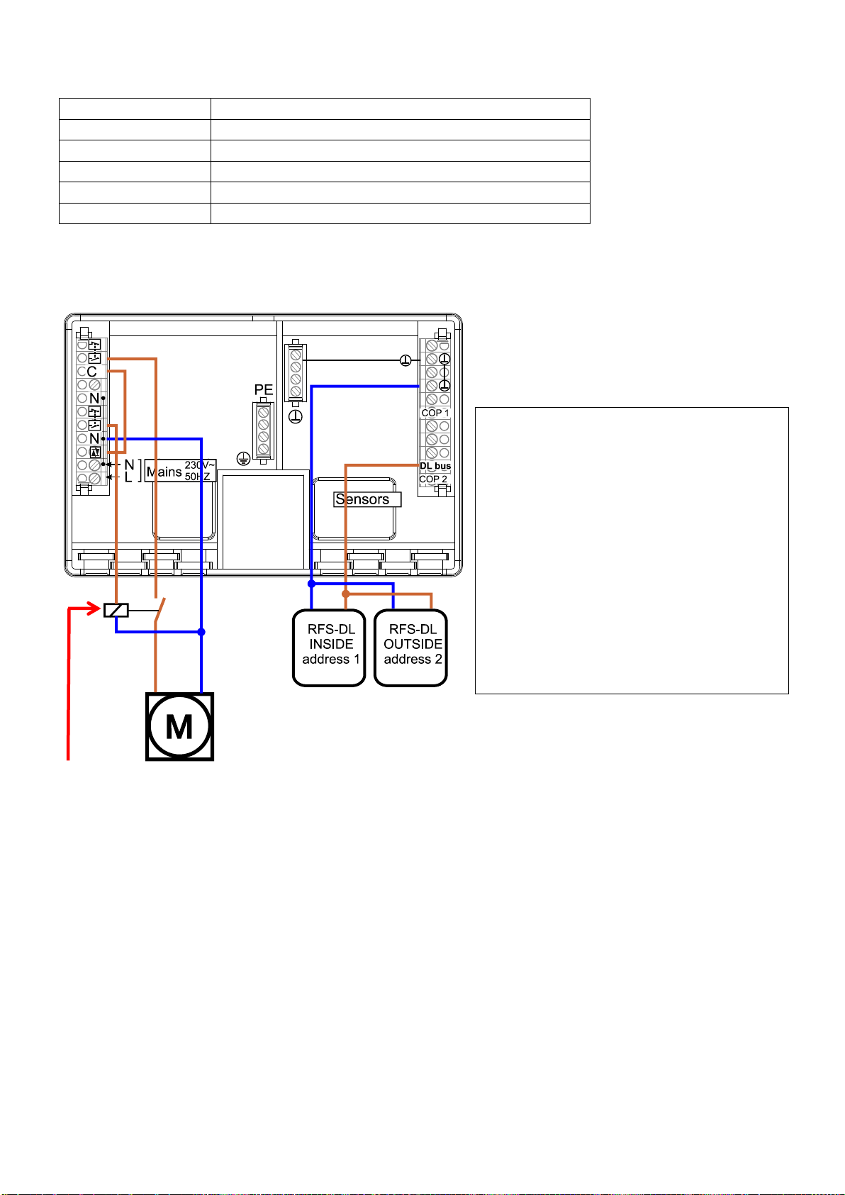
Application 1
Room drying only
The humidity should be lowered in a humid room. As soon as the absolute exterior humidity is lower
than the one inside, a fan is switched on.
The fan runs if
-the absolute humidity is lower outside than inside and
-the optional interval switch ("Timer") is active.
Recommended settings for UVR61-3
Menu
ENTER Par
Code: 32
Menu
ENTER Men
Code: 64
Program PR
0
EXT DL
Linking of output
LO
OFF
Ext. Sensor E1
14
max 1 /
75/70
no effect
Ext. Sensor E2
24
min 1 /
2/1
minimum humidity, inside
SENSOR (value transfer)
diff 1 /
1,0/0,5
minimum humidity differential,
outside/inside
TIMER optional
Sensor S1 ->
E1
Outputs
OPA 1
The fan is switched ON and OFF
alternately (ON and OFF time in
minutes).
Sensor S2 ->
E2
Release time
00:20
Block time
00:40
O1
Auto
Display
T1 and E1
Absolute interior humidity (g/m³, displayed in
°C)
T2 and E2
Absolute exterior humidity (g/m³, displayed in
°C)
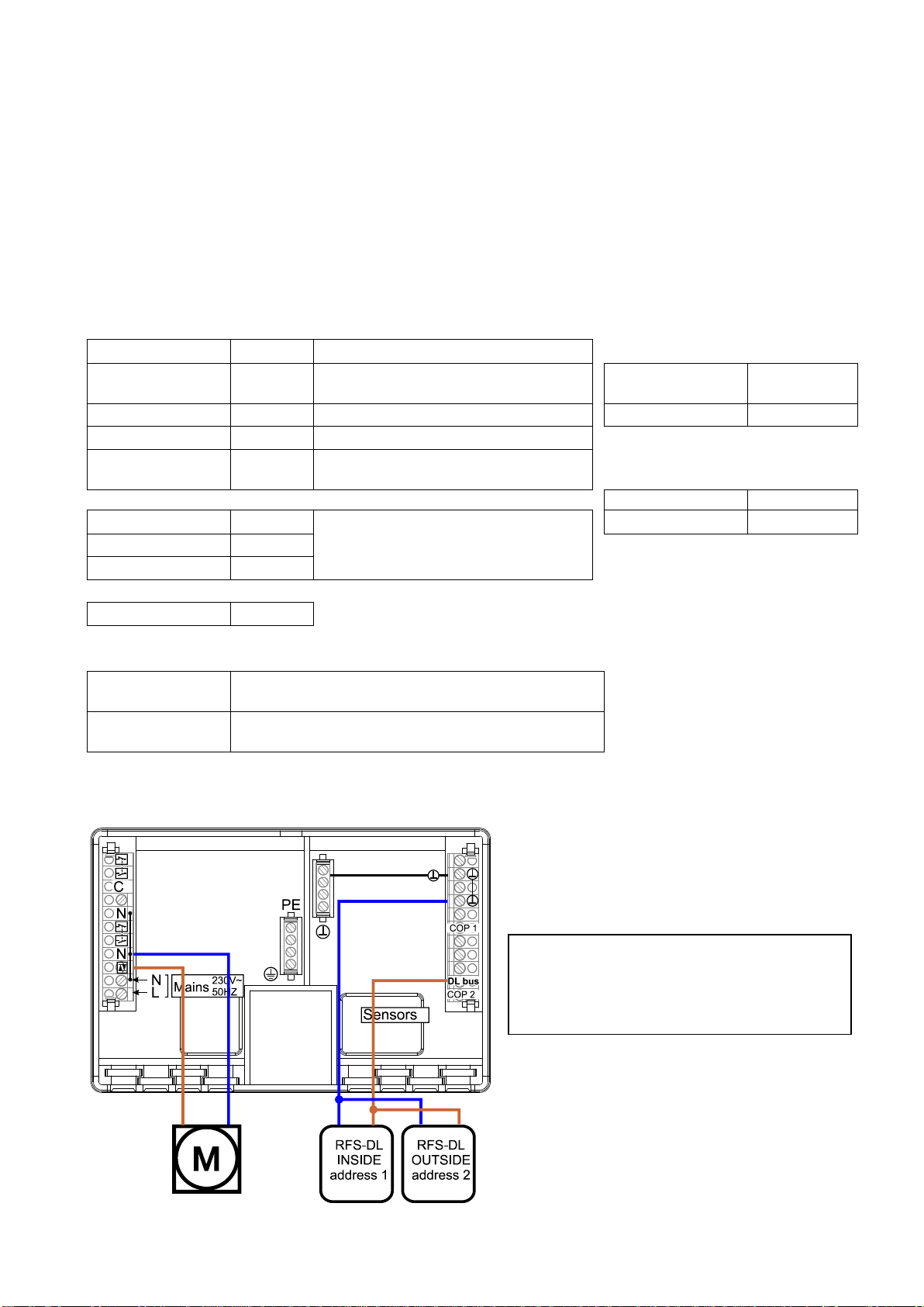
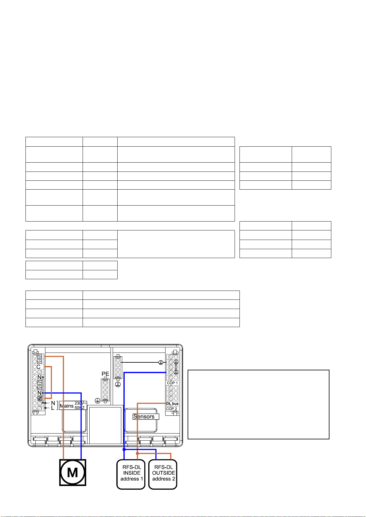
Electrical connection UVR61-3
Meaning of the luminous digits
1: Fan operation for room drying
activated
6
Application 2
Room drying with minimum temperature monitoring
The humidity should be lowered in a humid room. If a ventilated room is too cold, the fan is switched
off.
The fan runs if:
-the absolute humidity is lower outside than inside and
-the room temperature is high enough (protection against too much cooling down in the winter)
and the optional interval switch ("timer") is active.
Recommended settings for UVR61-3
Menu
ENTER Par
Code: 32
Menu
ENTER Men
Code: 64
Program PR
129
EXT DL
Linking of output
LO
OFF
Ext. Sensor E1
14
max 1 /
75/70
no effect
Ext. Sensor E2
24
max 3
10
minimum room temperature
Ext. Sensor E3
22
min1 /
2/1
minimum humidity, inside
Ext. Sensor E4
12
min3
9
If the temperature falls below this
room temperature, the fan is blocked.
diff1 /
1,0/0,5
minimum humidity differential,
outside/inside
SENSOR (value transfer)
TIMER optional
Sensor S1
E1
Outputs
OPA 1
The fan is switched ON and OFF
alternately (ON and OFF time in
minutes).
Sensor S2
E2
Release time
00:20
Sensor S3
E3
Block time
00:40
Sensor S4
E4
O1
Auto
O3
Auto
Anzeige
T1 and E1
Absolute interior humidity (g/m³, displayed in °C)
T2 and E2
Absolute exterior humidity (g/m³, displayed in °C)
T3 and E3
Exterior temperature
T4 and E4
Interior room temperature
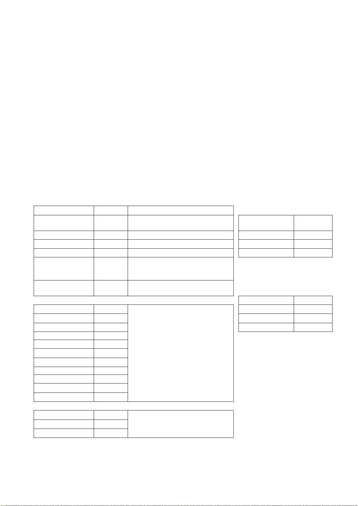
Electrical connection UVR61-3 Output 3 must be made potential-free. For
this, the red jumper on the rear of the detacha-
ble upper controller part is removed.
Meaning of the luminous digits
1: Fan operation for room drying activated
3: Fan operation for room drying blocked
because the room temperature is too
low
7
Application 3
Room drying with minimum temperature monitoring and
“Comfort ventilation”
The humidity should be lowered in a humid room. If a ventilated room is too cold, the fan is switched
off.
In order to guarantee a minimum room air quality for every day, even on days
-with humid exterior air or
-a drop below the set minimum room temperature
the fan is switched on with “comfort ventilation” for one or several time windows, preferable in the cool
morning hours.
The fan for room drying runs if:
-the absolute humidity is lower outside than inside and
-the room temperature is high enough (protection against too much cooling down in the winter)
and the optional interval switch ("Timer") is active.
The fan for “comfort ventilation” runs
-Daily according to time window
Recommended settings for UVR61-3
Menu
ENTER Par
Code: 32
Menu
ENTER Men
Code: 64
Program PR
129
EXT DL
Linking of output
LO
OFF
Ext. Sensor E1
14
max 1 /
75/70
no effect
Ext. Sensor E2
24
max 3
10
minimum room temperature
Ext. Sensor E3
22
min1 /
2/1
minimum humidity, inside
Ext. Sensor E4
12
min3
9
If the temperature falls below this
room temperature, the fan is
blocked.
diff1 /
1,0/0,5
minimum humidity differential,
outside/inside
SENSOR (value transfer)
TIME W
Sensor S1
E1
Time window 1
Within this time window, the fan
runs independently of the humidity
and temperature conditions.
Sensor S2
E2
Outputs
OPO 2
Sensor S3
E3
Time on/off
4.00/4.30
Sensor S4
E4
Time window 2
Outputs
OPO 2
Time on/off
5.30/6.00
Time window 3
Outputs
OPO 2
Time on/off
7.30/8.00
TIMER optional
Outputs
OPA 1
The fan is switched ON and OFF
alternately (ON and OFF time in
minutes).
Release time
00:20
Block time
00:40
8
O1
Auto
O2
Auto
O3
Auto
Display
T1 and E1
Absolute interior humidity (g/m³, displayed in °C)
T2 and E2
Absolute exterior humidity (g/m³, displayed in °C)
T3 and E3
Exterior temperature
T4 and E4
Interior room temperature
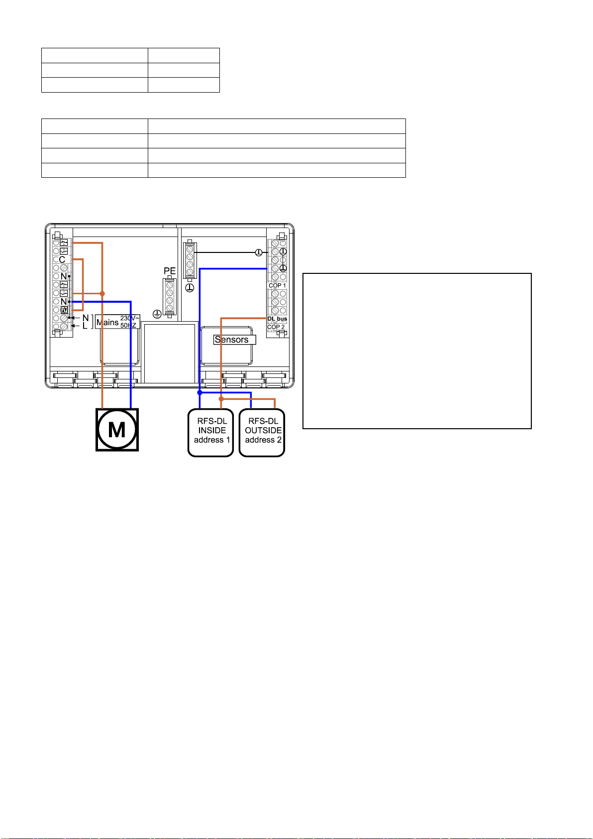
Electrical connection UVR61-3
Output 3 must be made potential-free. For
this, the red jumper on the rear of the detacha-
ble upper controller part is removed.
Meaning of the luminous digits
1: Fan operation for room drying activated
2: Fan operation for “comfort ventilation”
activated
3: Fan operation for room drying blocked
because the room temperature is too
low
9
Application 4
Room drying and "comfort ventilation", both with
minimum temperature monitoring
The humidity should be lowered in a humid room. In order to ensure room air quality to a large extent,
the fan is switched on for one or several time windows, preferably in the cool morning hours, even on
days with humid exterior air. If the set minimum room temperature is fallen short of, this “Comfort ven-
tilation” will also be blocked.
The fan for room drying runs if:
-the absolute exterior humidity is lower than the interior one and
-the room temperature is high enough (protection against too much cooling down in the winter)
and the optional interval switch ("Timer") is active.
The fan for “comfort ventilation” runs
-daily according to time window if the room temperature is high enough.
Recommended settings for UVR61-3
Men
ENTER Par
Code: 32
Menu
ENTER Men
Code: 64
Program PR
129
EXT DL
Linking of output
LO
OFF
Ext. Sensor E1
14
max 1 /
75/70
no effect
Ext. Sensor E2
24
max 3
10
minimum room temperature
Ext. Sensor E3
22
min1 /
2/1
minimum humidity, inside
Ext. Sensor E4
12
min3
9
If the temperature falls below this
room temperature, the fan is
blocked.
diff1 /
1,0/0,5
minimum humidity differential,
outside/inside
SENSOR (value transfer)
TIME W
Sensor S1
E1
Time window 1
Within this time window, the fan
runs if the room temperature
exceeds the max 3 value.
Sensor S2
E2
Outputs
AGO 2
Sensor S3
E3
Time on/off
4.00/4.30
Sensor S4
E4
Time window 2
Outputs
AGO 2
Time on/off
5.30/6.00
Time window 3
Outputs
AGO 2
Time on/off
7.30/8.00
TIMER optional
Outputs
AGU 1
The fan is switched ON and OFF
alternately (ON and OFF time in
minutes).
Release time
00:20
Block time
00:40
O1
Auto
O2
Auto
O3
Auto

10
Display
T1 and E1
Absolute interior humidity (g/m³, displayed in °C)
T2 and E2
Absolute exterior humidity (g/m³, displayed in °C)
T3 and E3
Exterior temperature
T4 and E4
Interior room temperature
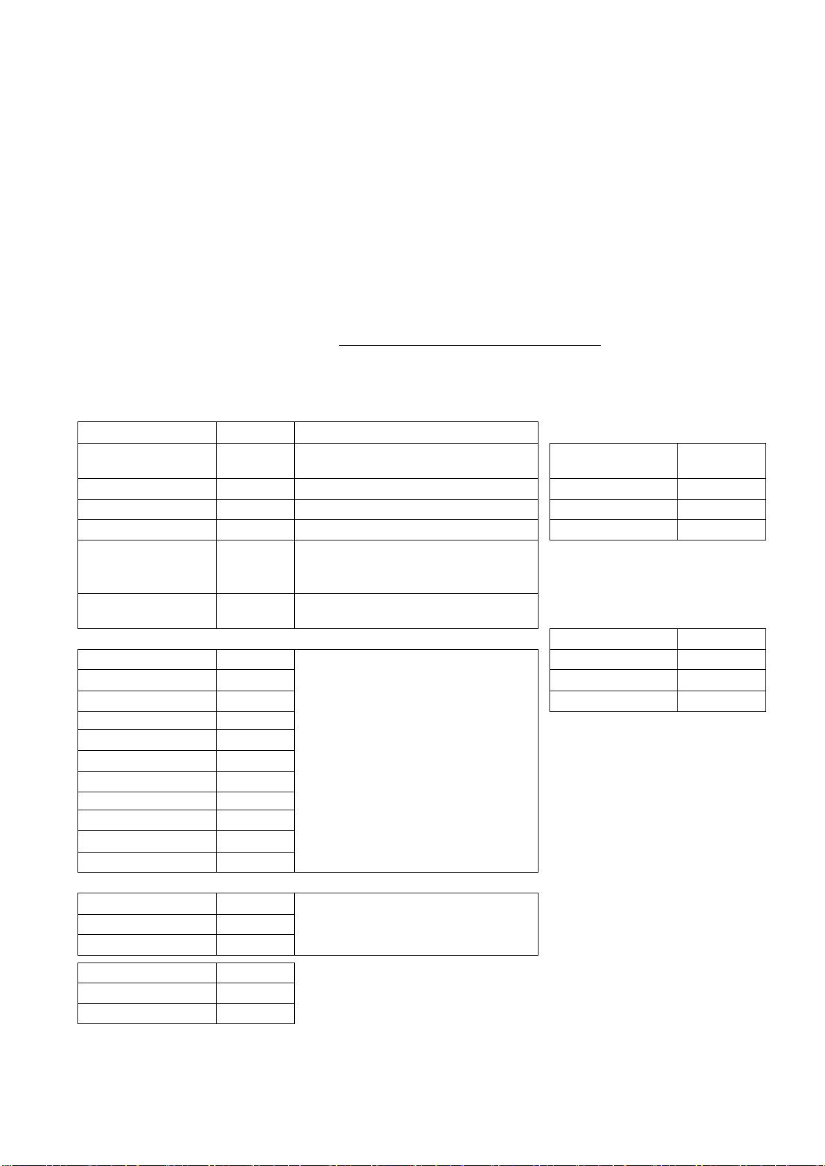
Electrical connection UVR61-3 Output 3 must be made potential-free.
For this, the red jumper on the rear of the
detachable upper controller part is re-
moved.
Meaning of the luminous digits
1: Fan operation for room drying activated
2: Fan operation for “comfort ventilation”
activated
3: Fan operation for room drying or com-
fort ventilation blocked because the
room temperature is too low

11
Application 5
Room drying with room temperature monitoring and
“comfort ventilation” for a wine cellar
The humidity should be lowered in a wine cellar. In order to ensure room air quality to a large extent,
the fan is switched on for one time window regardless of the room temperature (“comfort ventilation”)
even on days with humid exterior air.
The fan for room drying runs if:
-the absolute exterior humidity is lower than the interior one and
-the relative interior humidity is higher than e.g. 60% and
-the room temperature is above the required temperature (example: 10C) and
-the optional interval switch ("Timer") is active.
The fan for “comfort ventilation” runs
-daily according to the time window regardless of other settings (example: 10:00 to 10:30 a.m.),
up to three time windows can be set
Recommended settings for UVR61-3
Menu
ENTER Par
Code: 32
Menu
ENTER Men
Code: 64
Program PR
512
EXT DL
Linking of out-
put LO
OFF
Ext. Sensor E1
11
max 1 /
75/70
no effect
Ext. Sensor E2
21
max 2 /
100/95
no effect
Ext. Sensor E3
12
max 3 /
50/45
no effect
Ext. Sensor E4
22
min 1 /
2/1
Start threshold for inside absolute
humidity in g/m³ (display: °C)
Ext. Sensor E5
14
min 2 /
62/60
Start threshold for relative humidity in
% (display: °C)
Ext. Sensor E6
24
min 3 /
11/10
Start threshold for room temperature in
°C
diff 1 /
1,0/0,5
Minimum differential, absolute humidity
outside - inside
SENSOR
(value transfer)
diff 2
--
Set diff 2 and diff 3 to "unused" (setting
over 98 °C, display: --)
Sensor S1
E5
diff 3
--
Sensor S2
E6
Sensor S3
E1
TIME W
Sensor S4
E2
Time window 1
Within this time window, the fan runs
independently of the humidity and
temperature conditions.
Sensor S5
E3
Outputs
OPO 123
Sensor S6
E4
Time on/off
10:0/10:30
Timer optional
Outputs
OPA 1
The fan is switched ON and OFF
alternately (ON and OFF time in
minutes).
Release time
00:10
Block time
00:10
O1
Auto
O2
Auto
O3
Auto
With time window setting OPO 12, “comfort ventilation” takes place only if the room temperature has
exceeded the temperature threshold.
12
Display
T1 and E5
Absolute interior humidity (g/m³, displayed in °C)
T2 and E6
Absolute exterior humidity (g/m³, displayed in °C)
T3 and E1
Relative interior humidity (%, displayed in °C)
T4 and E2
Relative exterior humidity (%, displayed in °C)
T5 and E3
Interior temperature
T6 and E4
Exterior temperature
Electrical connection UVR61-3 Output 3 must be made potential-free.
For this, the red jumper on the rear of the
detachable upper controller part is re-
moved.
An external auxiliary relay whose contact is arranged in series with both other outputs is connected
to output 2.
We reserve the right to make technical changes ©2017
Meaning of the luminous digits
1: Fan operation for room drying acti-
vated (interval operation) via abso-
lute humidity
2: Activated if relative interior humidity
is above the turn-on threshold
3: Activated if the room temperature is
above the temperature threshold
The fan runs only if all three luminous
digits are illuminated
Other manuals for UVR61-3
1
Table of contents


