Tecnogas TEO706MB User manual

MIDI OVEN
SERVICE MANUAL
2018 DECEMBER

CONTENTS
1. WARNINGS 3
1.1. General Safety Warnings 3
1.2. Safety For Montage 3
1.3. Information For Consumers 4
2. MIDI OVEN MODELS 5
2.1. 34 Liter 5
2.1.1. Technical Specifications 5
2.1.2. Technical Tables 6
2.1.3. Description Of Oven And Control Panel 8
2.1.4. Component Disassembly/Assembly 9
2.1.5. Circuit Diagrams 19
2.2. 35 Liter 20
2.2.1. Technical Specifications 20
2.2.2. Technical Tables 21
2.2.3. Description Of Oven And Control Panel 24
2.2.4. Component Disassembly/Assembly 25
2.2.5. Circuit Diagrams 36
2.3. 40 Liter 37
2.3.1. Technical Specifications 37
2.3.2. Technical Tables 38
2.3.3. Description Of Oven And Control Panel 41
2.3.4. Component Disassembly/Assembly 42
2.3.5. Circuit Diagrams 52
2.4. 42 Liter 53
2.4.1. Technical Specifications 53
2.4.2. Technical Tables 54
2.4.3. Description Of Oven And Control Panel 57
2.4.4. Component Disassembly/Assembly 58
2.4.5. Circuit Diagrams 68
2.5. 45 Liter 71
2.5.1. Technical Specifications 71
2.5.2. Technical Tables 72
2.5.3. Description Of Oven And Control Panel 76
2.5.4. Component Disassembly/Assembly 77
2.5.5. Circuit Diagrams 87
2.6. 70 Liter 91
2.6.1. Technical Specifications 91
2.6.2. Technical Tables 92
2.6.3. Description Of Oven And Control Panel 94
2.6.4. Component Disassembly/Assembly 95
2.6.5. Circuit Diagrams 108
2.7. Midi Oven With Hotplate (35, 40 and 42 Liter Oven) 112
2.7.2. Circuit Diagrams 150
3. IF THE OVEN DOES NOT WORK 153

3
1. WARNINGS
This product is manufactured in accordance with the safety regulations. Throughout this user
manual the following symbols are used.
1.1. General Safety Warnings
The product must be disconnected during installation, maintenance and repair.
Rear surface of the oven gets hot when it is in use. Make sure that the electrical connection does
not contact the rear surface; otherwise, connections can get damaged.
Be careful not to use the damaged component and replace it with a new one.
Make sure that loose and damaged cables are not used.
When replacing electrical components, be sure that there is no liquid or moisture on the new used
part.
If the power plug is damaged, do not use the product.
For safety reasons, do not extend the cable by means of an attachment, and do not use an
extension cable.
Make sure that fuse rating is compatible with the product.
1.2. Safety For Montage
Product must be placed directly on the flat floor. If the floor is not flat, ask the customer to adjust
the floor planability.
The mains cable should not be over hot surfaces during installation. As a result of melting the
cable, you may cause the product to short circuit and fire.
Make sure that the cables are not cut and damaged during installation. If it is cut and damaged,
replace it with a new one.
Important information or useful hints about usage.
Warning of hazardous situations with regard to life and property.
Warning of electric shock.
Warning of risk of fire.
Warning of hot surfaces.

4
1.3. Information For Consumers
Product may be hot when it is in use. Never touch the hot burners, inner sections of the oven,
heaters and etc. Do not place flammable substances near the product while working.
Never wash the product by spraying or pouring water onto it. There is danger of electric shock!
Do not heat closed cans and glass jars in the product. Pressure can cause the jar to explode.
Never try to clean when the appliance works.
Do not make any repairs or changes to the product. However, you may be able to correct some
of the problems indicated in the manual for using the oven.
Do not place baking trays, plates or aluminium foil directly on the product base. Accumulated
heat can damage the base of the product.
Placing food in hot oven, taking food out, etc. always use heat resistant oven gloves.
Do not use the product with the front cover glass removed or broken.
Ensure that children do not sit on the cover glass while it is open.
Do not hang cloth, towel or similar materials on the product handle.

5
2.MIDI OVEN MODELS
2.1. 34 Liter
2.1.1. Technical Specifications:
SPECIFICATIONS
34 LTR
Outer Width
480 mm
Outer Depth
356 mm
Outer Height
300 mm
Inner Width
364 mm
Innet Depth
315 mm
Inner Height
240 mm
Thermostat
40-240 ◦C
Timer
0-90 min.
Bottom Heater
650 W
Top Heater
650 W
Supply Voltage
220-240 V / 50-60 Hz
Turnspit(Option)
6 W
Oven Lamp(Option)
15-25 W
Grill Resistance(Option)
1300 W

6
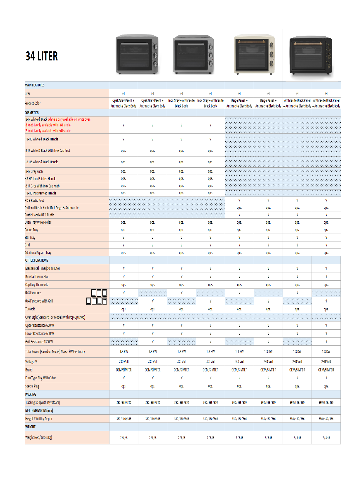
2.1.2. Technical Tables:
*All models are included.
7
H / W / D (mm)
8
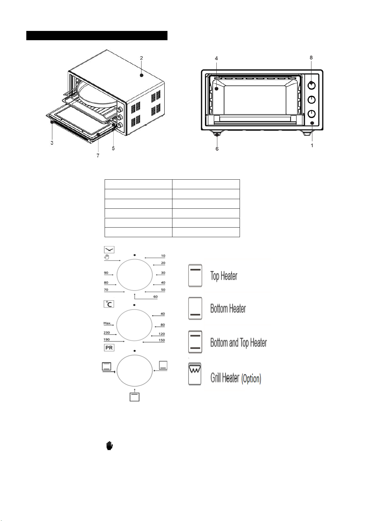
2.1.3. Description Of Oven And Control Panel:
1. Control Panel
7. Glass Oven Door
2. Oven Frame
8. Control Knobs
3. Handle
9. Round Tray
4. Vessel
10. Square Tray
5. Heaters
11. Rack Grill
6. Oven Feet
Timer: Set the timer according to the recommended cooking time at the desired thermostat
value. When the set time is ended, timer cuts the power of heaters and warns with a buzzer
sound. To turn off the device, bring the timer, program and thermostat buttons to zero position.
When the timer is positioned on its position it will work continuously.
Thermostat: Thermostat provides 40-240°C heat range in the oven.

9
2.1.4. Component Disassembly/Assembly:
1) Knobs
Photo 1
Photo 2
Pull back standard knobs on panel and take them out.
10
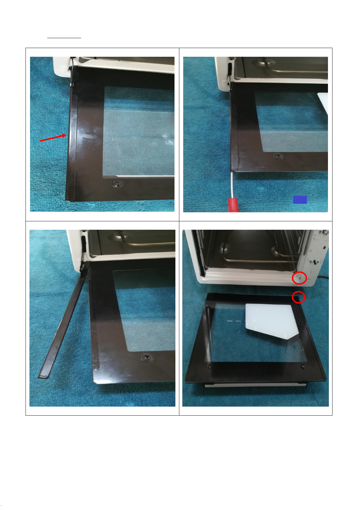
2) Cover Glass
Photo 1
Photo 2
Photo 3
Photo 4
Separate the metal from glass carefully with the help of a screwdriver, without damaging to the glass and
take out glass by paying attention to the hole on right.
11
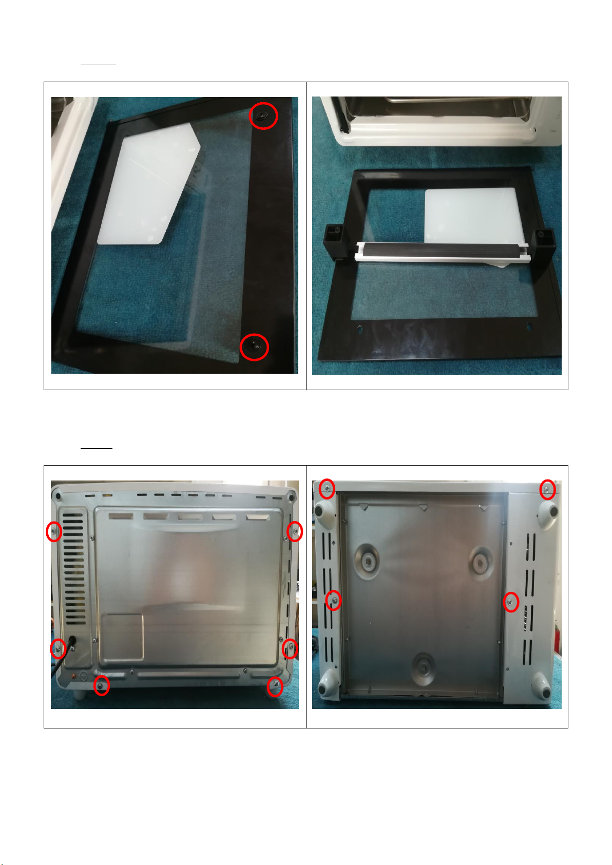
3) Handle
Photo 1
Photo 2
Remove two screws that connect handle to glass and take out it.
4) Frame
Photo 1: Rear View
Photo 2: Sub-View
12
Photo 3: Final Situation
Remove the screws on rear surface and sub-surface to take out frame.
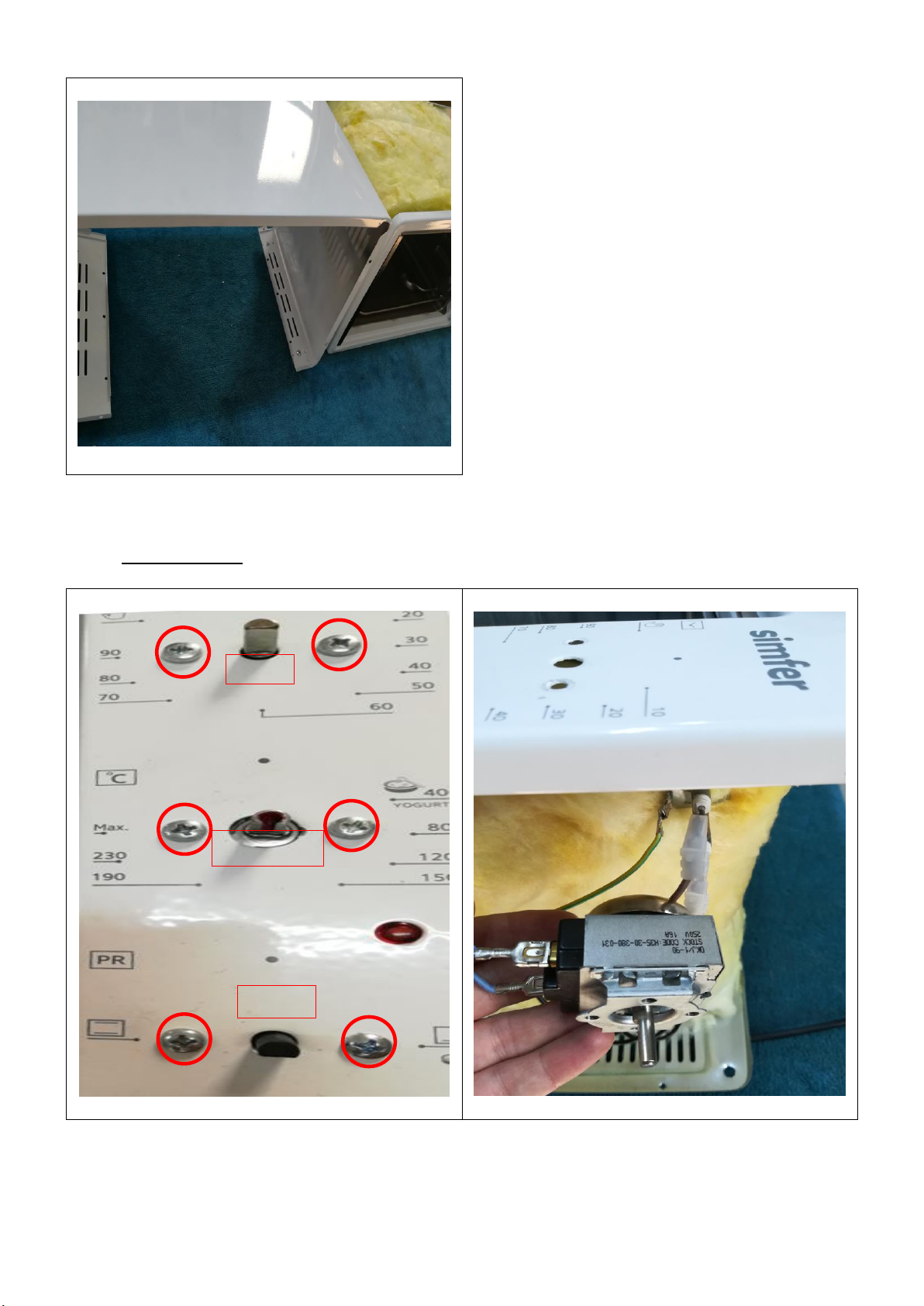
5) Mechanic Timer
Photo 1
Photo 2
Remove screws to take out the mechanic timer and disconnect cables carefully.
Timer
Thermostat
Switch
13
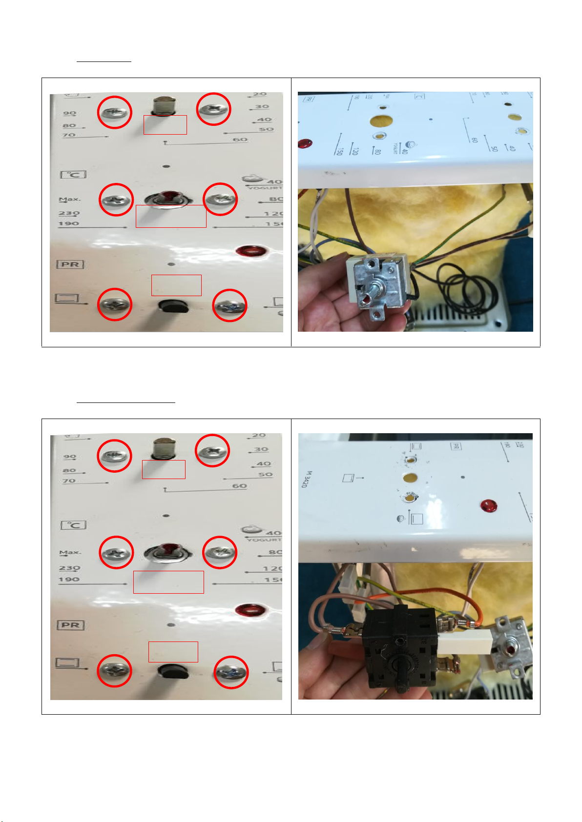
6) Thermostat
Photo 1
Photo 2
Remove screws to take out the thermostat and disconnect cables carefully.
7) Switch(Commutator)
Photo 1
Photo 2
Remove screws to take out the switch and disconnect cables carefully.
Timer
Thermostat
Switch
Timer
Thermostat
Switch

14
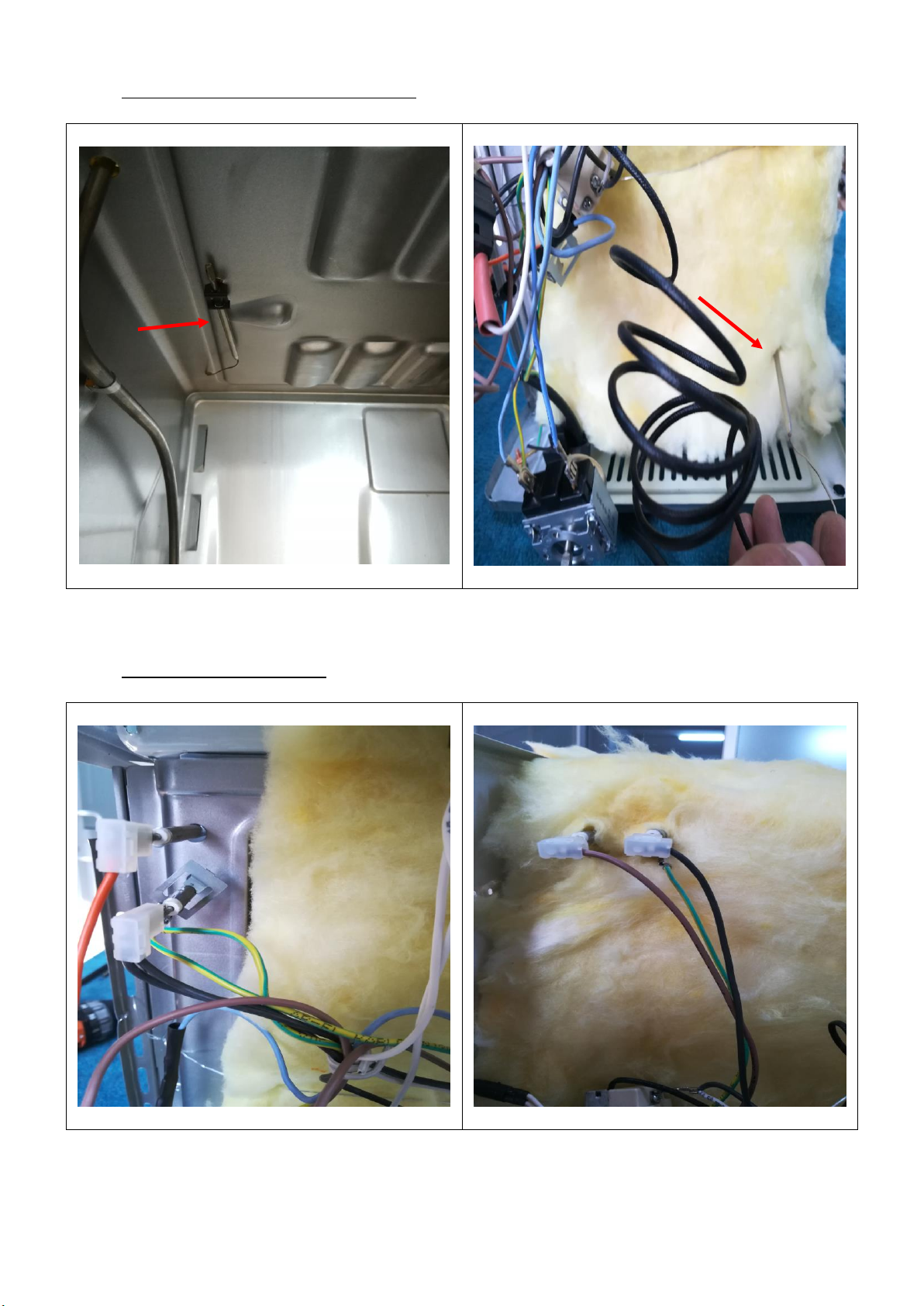
8) Metal Spring
Photo 1
Photo 2
Take out the metal spring to disassemble front panel.
9) Front Panel
Photo 1
Photo 2
Remove 4 screws to take out front panel. When take out panel, please pay attention to tabs.
15
10) Thermostat Stick(Capillary Thermostat)
Photo 1
Photo 2
Follow steps to take out stick according to photographs.
11) Bottom And Top Resistance
Photo 1
Photo 2
Disconnect cable connections for resistances.
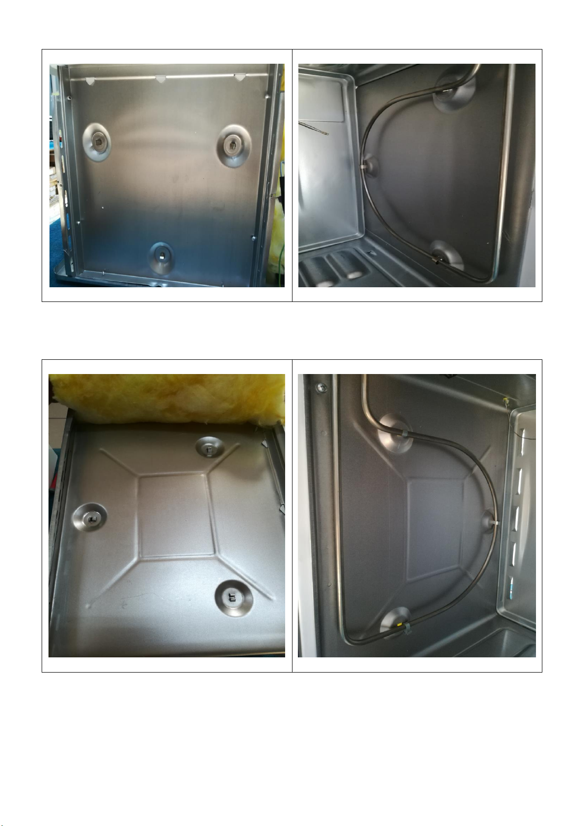
16
Photo 3: Sub-surface
Photo 4
Press clips with pliers from outside for bottom resistance and get out from inside clips that connect the
resistance to the inside of body. Remove resistance pulling back from the hole on side.
Photo 5:Top Surface
Photo 6
Press clips with pliers from outside for top resistance and get clips out from inside that connect the
resistance to the inside of body. Remove resistance pulling back from the hole on side.

17
12) Plug
Photo 1
Photo 2
Cut the heat shrink and disconnect cables carefully. Finally remove nut to replace plug.
13) Oven Lamp (If you don’t have oven lamp in your product, please skip this step.)
Photo 1
Turn the lamp glass and oven lamp to replace and flex slot to take out lamp holder after disconnecting
cables.
18
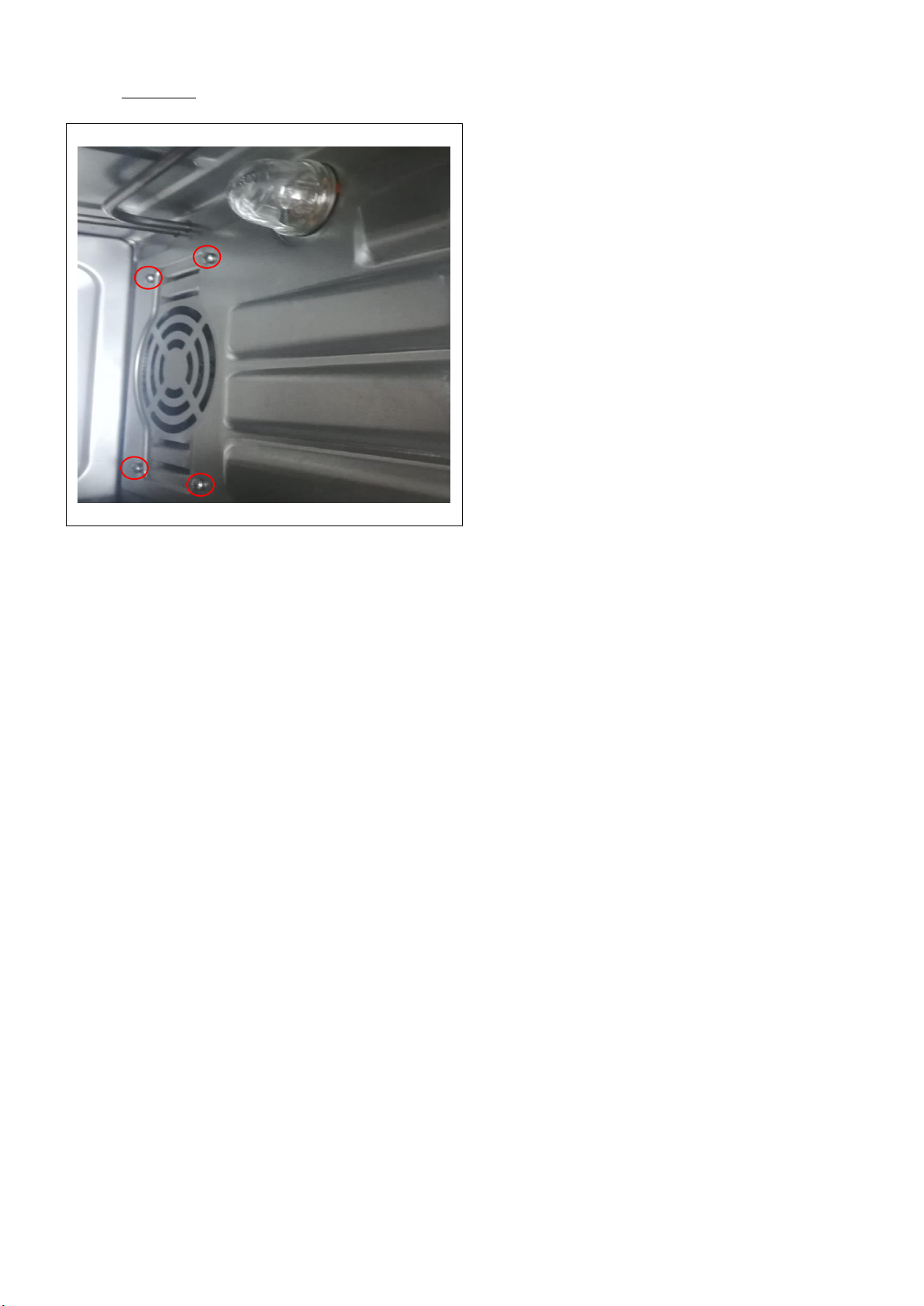
14) Turbo Fan (If you don’t have turbo fan in your product, please skip this step.)
Photo 1
Remove screws and disconnect cable connections to get turbo fan out.

19
2.1.5. Circuit Diagrams:
*If you have another product except these options, please ask an expert or contact with us.
Midi oven 0+3 without oven lamp
Midi oven 0+3 turnspit option without oven lamp

20
2.2. 35 Liter
2.2.1. Technical Specifications:
SPECIFICATIONS
35 LTR
Outer Width
495 mm
Outer Depth
380 mm
Outer Height
300 mm
Inner Width
350 mm
Innet Depth
310 mm
Inner Height
240 mm
Thermostat
40-240 ◦C
Timer
0-90 min.
Bottom Heater
600 W
Top Heater
600 W
Supply Voltage
220-240 V / 50-60 Hz
Turbo Fan(Option)
13-15 W
Turnspit(Option)
6 W
Oven Lamp(Option)
15-25 W
Grill Resistance(Option)
900 W
Hotplate(Option)
ø180 HP 900 W
ø145 HP 600 W
ø80 HP 300–300 W
Table of contents
Other Tecnogas Oven manuals


